
-
Contents
-
Table of Contents
-
Troubleshooting
-
Bookmarks
Quick Links
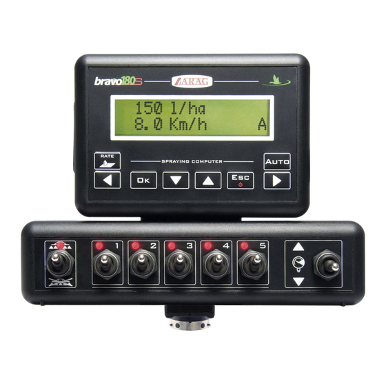
BRAVO 180S SERIES COMPUTER
CROP SPRAYING
46718XXXX
Software rel. 1.10.x
INSTALLATION, USE AND MAINTENANCE
Related Manuals for ARAG Bravo 180S Series
Summary of Contents for ARAG Bravo 180S Series
-
Page 1
BRAVO 180S SERIES COMPUTER CROP SPRAYING 46718XXXX Software rel. 1.10.x INSTALLATION, USE AND MAINTENANCE… -
Page 2: Legend Of Symbols
This manual is an integral part of the equipment to which it refers and must accompany the equipment in case of sale or change of ownership. Keep it for any future reference; ARAG reserves the right to modify product specifications and instructions at any moment and without notice.
-
Page 3: Table Of Contents
CONTENTS • Legend of symbols …………..2 12 User setting …………….25 12.1 Jobs setup …………..26 • Manual foreword and use …………4 12.2 Nozzle data * …………..27 • Manual use modes …………..4 12.3 Minimum regulation pressure * ……..28 12.4 Wheel selection ** …………28 •…
-
Page 4: Manual Foreword And Use
• RESPONSIBILITY The installer must carry out workmanlike installations and ensure to the end user the perfect operation of the whole system both with ARAG components only and other brands’ components. ARAG always recommends using its components to install control systems.
-
Page 5: Product Description
BRAVO DSB ARAG has designed and manufactured a diagnostics system for Bravo series computers and the systems they may be connected to. BRAVO DSB (code 467003) provides reliable diagnostics of computer, control unit or the whole system troubleshooting any potential problems experienced with the BRAVO DSB system.
-
Page 6: Package Content
INSTALLATION PACKAGE CONTENT The table below indicates the components that you will find in the BRAVO computer package: BRAVO 180S COMPUTER Legend: 1 Bravo 180S 2 Instruction manual (DVD-ROM) 3 Power cable 4 Fixing kit 5 Power supply connector 6 Valve and sensor harness 7 Inductive speed sensor 8 Section valve connector seals Fig.
-
Page 7: Position On Farming Machine
INSTALLATION POSITION ON FARMING MACHINE System recommended composition ASSEMBLY DIAGRAM FOR SPRAYER WITH DIAPHRAGM PUMP SYSTEM WITH MAIN VALVE Legend: Monitor Battery GPS receiver (optional) Filling pump Flowmeter External general control / external speed sensor Level sensor Pressure sensor Foam marker (crop spraying only) Speed sensor Control valve…
-
Page 8
INSTALLATION ASSEMBLY DIAGRAM FOR SPRAYER WITH CENTRIFUGAL PUMP Legend: Monitor Battery GPS receiver (optional) Filling pump Flowmeter External general control / external speed sensor Level sensor Pressure sensor Foam marker (crop spraying only) Speed sensor Control valve 1÷5 Section valves Hydraulic unit INTENDED APPLICATIONS Fig. -
Page 9: Computer Positioning
• BRAVO 180S series computer must be placed in the control cabin of the farming machine. Observe the following precautions: — Do NOT install the monitor in areas where it would be subjected to excessive vibrations or shocks, to prevent any damage or accidental use of the control keys;…
-
Page 10: Bracket Fixing
WARNING! DO NOT CONNECT HYDRAULIC UNITS OTHER THAN THE SPECIFIED ONES (SEE ARAG GENERAL CATALOGUE). ARAG IS NOT LIABLE FOR ANY DAMAGE TO THE PRODUCT, MALFUNCTION ERRORS AND ANY KIND OF RISK IF THE MODULE IS CONNECTED TO NON ORIGINAL UNITS OR UNITS NOT SUPPLIED BY ARAG.
-
Page 11: Computer Connection To The Farming Machine
INSTALLATION COMPUTER CONNECTION TO THE FARMING MACHINE General precautions for a correct harness position • Securing the cables: — secure the harness so that it does not interfere with moving parts; — route the harnesses so that they cannot be damaged or broken by machine movements or twisting. •…
-
Page 12: Power Supply Connection
INSTALLATION Power supply connection The package includes the power connector (Fig. 1 and Fig. 2 on page 6) to be connected to the farming machine battery; Fig. 13 shows the drilling template of the power connector. Connect the power connector to the battery wires using two 0.250″ faston connectors, as indicated in Fig. 11 and Fig. 12. Use the cable provided with the package (Fig.
-
Page 13: Harness Connection To The Control Unit, The Hydraulic Unit And The Available Functions
• Take care not to break, pull, tear or cut the cables. • Use of unsuitable cables not provided by ARAG automatically voids the warranty. • ARAG is not liable for damages to the equipment, persons or animals caused by failure to observe the above instructions. Multicore cable connection Connect the multicore cable to the monitor (connections 1 and 2 on page 9) and the other cable end to the control unit and the hydraulic unit.
-
Page 14: Hydraulic Valve Connection
INSTALLATION Hydraulic valve connection Bravo 180S can control up to 7 hydraulic functions through double-acting valves. Fix the connectors to the relevant valves according to the initials indicated in your assembly general diagram (7.1 System recommended composition). • Position seal ( ) onto connector ( ), then connect the latter pressing it fully home ( during this operation, take special care not to bend valve electric contacts.
-
Page 15: Connection Of Sensors And Other Available Functions
• pressure sensor; • level sensor • foam marker. All ARAG sensors use the same type of connector. Connect the sensor connector to the relevant harness; make sure it is correctly fitted and push it until locking it. Fig. 18 Fig.
-
Page 16: Setup
SETUP SETUP 10.1 Computer switching on/off • Ordinary switching on Software version Bravo 180S — — — — — M e n u — — — — — SPR Ver 1.8.0 — — — S p ray i ng — — Fig.
-
Page 17: Use Of Keys For Setup
SETUP 10.2 Use of keys for setup Language English 1 Press the arrow keys in succession to move across the menu items. next item, previous item); the selected item will be displayed (Fig. 23). Units of measur. 2 Press to access the menu: during set-up, a cursor blinks on the display (Fig.
-
Page 18: Advanced Setup
ADVANCED SETUP ADVANCED SETUP The computer can be set-up with the all data required to ensure a correct distribution of the treatment product. This operation must be done once only, when installing the computer. 11.1 Tests and checks before programming Before proceeding with computer programming check the correct installation of all components (control unit and sensors), the connection to the power supply and the connection to the components (general control unit and sensors).
-
Page 19: Language
ADVANCED SETUP 11.2 Language Language Set the language of Bravo 180S, among those available. English > Italian, English, Spanish, Portuguese, French, German, Polish, Croatian, Hungarian, Greek, Russian, Turkish, Czech. Fig. 29 11.3 Units of measur. Set the units of measurement used for Bravo 180S. Units of measur.
-
Page 20: Device Connect
ADVANCED SETUP 11.6 Device connect. Enable / disable any connection to an external. Ext. device > Device connect. Serial LOG External device None Ext. device setup enables Bravo 180S to receive the spraying data of the variable application rate from serial LOG a connected device (e.g.: DELTA 80), the item transmits, in turn, to the serial port a string of data…
-
Page 21: Valves
: indicate the type of installed main control valve. 2-Ways : drain valve (valve TYPE — Arag 463 series) 3-Ways : main valve (valve TYPE — Arag 464 — 471 series) 11.10 Flowmeter Flowmeter Select the type of flowmeter installed:…
-
Page 22: Flowmeter Constant
ADVANCED SETUP 11.11 Flowmeter constant This parameter sets the flowmeter constant value: it indicates how many pulses are sent by the flowmeter per unit of Flowmeter sprayed fluid. 2271 pls/gal The constant value is indicated on the label on your flowmeter. For the parameter value of ORION flowmeters only, to be entered in the computer, refer to section «Technical data»…
-
Page 23: Tank Source
ADVANCED SETUP 11.16 Tank source In this menu select a tank level reading mode. Tank source The management of the , described in par. 11.17, will be different according to the selected mode. Tank source Possible options: Manual > Manual Level Sensor The level sensor installed in the system allows displaying the tank level in real time.
-
Page 24: Spraying Menu
ADVANCED SETUP 9 Immediately after that, the computer passes to the calibration start screen: Calib. phase Calib. phase Activate Main > the display shows the message Activate Main 10 Start the spraying system: open, in succession, ALL section valves and the main control (switches in position Calib.
-
Page 25: User Setting
USER SETTING USER SETTING Before starting a treatment, some settings are necessary for a correct job. Once all necessary data have been set, it is possible to immediately start spraying. ACCESS TO THE USER MENU User setting (from computer on) •…
-
Page 26: Jobs Setup
USER SETTING 12.1 Jobs setup In this menu it is possible to set 10 different types of treatments. 1/10 32.1 GPA — First select the job to be set (Fig. 59). Job number Fig. 59 Rate Type Rate Type — After selecting the job, the computer automatically passes to the setting screen of for the selected treatment (Fig.
-
Page 27: Nozzle Data
USER SETTING 12.2 Nozzle data This menu allows setting and viewing the values of the nozzles being used. Nozzles type Nozzles type — First select , Fig. 62). — Then the computer automatically passes to the selection of the nozzle to be set (Fig. 63). ISO nozzles CAN NOT BE MODIFIED.
-
Page 28: Minimum Regulation Pressure
USER SETTING 12.3 Minimum regulation pressure This menu allows setting a pressure value below which BRAVO 180S blocks the automatic regulation function Min. reg. press. Disabled : block disabled). Disabled The control is active ONLY during treatment AUTOMATIC control (par. 14.3.1). For the procedure to be followed in case of alarms, please refer to par.
-
Page 29: Level Correction
USER SETTING 12.7 Level correction Level correction If the sprayed fluid has a different density than the water one, the computer could display wrong measurements; 133.53 oz/gal to correct them change the sprayed fluid weight for 1 l of product. Fig.
-
Page 30: Totalizers
USER SETTING 12.11 Totalizers • there is a totalizer for each preset job (10 available), plus the «T00» one (that can not be reset) which includes all jobs Totalizers performed by the device. Export • the current job data are summed to the relevant totalizer each time you select a new job (par. 14.1). Export •…
-
Page 31: Use
13.1 Display Percentage variation according to the set output value Active pendrive 32.1 GPA < Output value during treatment LEFT side of the active foam marker Master OFF > Disabled spraying RIGHT side of the active foam marker Tank level lower 32.1 GPA ƒ…
-
Page 32: Treatment Preliminary Settings
TREATMENT PRELIMINARY SETTINGS Par. 11.8 Speed sensor 11.5 Boom width 12.1 Job setup TO BE CARRIED OUT 12.2 Nozzle data UPON FIRST USE 12.3 Minimum regulation pressure OF THE COMPUTER After having carried out the indicated settings 12.5 Minimum speed start the treatment selecting between MANUAL 12.8 Display contrast…
-
Page 33: Application Rate Regulation
14.4 Automatic closure of the main valve BRAVO 180S can automatically switch off the main valve through an external ARAG* navigator: the navigator can autonomously manage valve opening and closing, thus preventing the overlapping of already-sprayed areas. To be able to use the automatic closure, connect the navigator to BRAVO 180S and perform the procedure for AUTOMATIC operation (par.
-
Page 34: Output Menu
14.5 Output menu This menu contains the description of the functions available during the treatment. A sub-menu is available for almost all data; to gain access to it press keys at the same time for 1 second. • Instantaneous speed indication The driving speed simulation allows spraying the product even without a Speed simul.
-
Page 35: Tank Filling
14.5.1 Tank filling Master OFF Spraying Menu Tank level 1 From the , press until selecting Tank level 2 Press the keys at the same time to access the tank filling procedure. Tank source The filling will be managed in different ways according to the mode preset in the menu (par.
-
Page 36: Maintenance / Diagnostics / Repairs
MAINTENANCE / DIAGNOSTICS / REPAIRS MAINTENANCE / DIAGNOSTICS / REPAIRS 15.1 Operation errors The indicated messages blink alternatively Machine stopped! 0.0 gpa 0.0 MPH 0.0 MPH Fig. 97 MESSAGE ON DISPLAY / Par. REMEDY MODE CAUSE MAN. Disable Main 13.2.2 •…
-
Page 37: Troubleshooting
MAINTENANCE / DIAGNOSTICS / REPAIRS 15.2 Troubleshooting FAULT CAUSE REMEDY • Check power supply connection (par. 8.2) No power supply The display does not switch on Computer is OFF • Press the ON key Valve controls take no effect Valves not connected •…
-
Page 38: Technical Data
MAINTENANCE / DIAGNOSTICS / REPAIRS TECHNICAL DATA • Advanced menu Data Description Min. Max. DEFAULT Other values that can be set / Notes English, Italian, Spanish, Portuguese, French, German, Language Display language English Polish, Croatian, Hungarian, Greek, Russian, Turkish, Czech.. Units of measur.
-
Page 39: Computer Technical Data
TECHNICAL DATA • Output values Data Min. Max. Description Notes 99999,9 US: GPA Quantity of sprayed fluid for unit of Volume applied Shown on the first line of the display, during treatment 0.00 99999,99 US TURF: GPK surface Speed 199,9 US — US TURF: MPH Vehicle driving speed Present only if YES has been set in the advanced…
-
Page 40: End-Of-Life Disposal
Dispose of the system in compliance with the established legislation in the country of use. GUARANTEE TERMS 1. ARAG s.r.l. guarantees this apparatus for a period of 360 days (1 year) from the date of sale to the client user (date of the goods delivery note).
-
Page 41
Notes… -
Page 42
Only use genuine ARAG accessories or spare parts to make sure manufacturer guaranteed safety conditions are maintained in time. Always refer to ARAG spare parts catalogue. 42048 RUBIERA (Reggio Emilia) — ITALY Via Palladio, 5/A Tel. +39 0522 622011 Fax +39 0522 628944 http://www.aragnet.com…
•
This manual provides instructions to assemble, connect and set the computers of the BRAVO 180S family.
Any other information is provided in specific sheets to be used exclusively by the installer, containing specific information of each computer model.
•
MANUAL USE MODES
The section of this manual dedicated to the installation contains information for installers. For this reason we have used technical terms without
providing explanations which would be necessary for end users only.
THE INSTALLATION MUST BE CARRIED OUT BY AUTHORISED AND SKILLED PERSONNEL ONLY. THE MANUFACTURER IS
NOT RESPONSIBLE FOR ANY OPERATION SPECIFIED IN THIS MANUAL CARRIED OUT BY UNAUTHORISED OR UNSKILLED
PERSONNEL.
•
LIMITATIONS
The descriptions of the assembly phases refer to a «general» computer, so specific models will not be mentioned, unless a certain installation procedure
concerns exclusively one computer type.
•
RESPONSIBILITY
The installer must carry out workmanlike installations and ensure to the end user the perfect operation of the whole system both with ARAG components
only and other brands’ components.
ARAG always recommends using its components to install control systems.
The installer will be held responsible for any malfunction if he decides to use other brands’ components even without actually changing the system
parts or harness.
The compatibility check with components and accessories of other manufacturers shall be carried out by the installer.
If the computer or the ARAG components installed together with other brands’ components get damaged because of what stated above, no direct or
indirect warranty will be provided.
4
INTRODUCTION
Manual, Installation, Use And Maintenance Handbook for ARAG Bravo 180S Series Farm Equipment (42 pages)
Specifications:1517/1517263-bravo_180s_series.pdf file (03 Apr 2023) |
Accompanying Data:
ARAG Bravo 180S Series Farm Equipment PDF Installation, Use And Maintenance Handbook (Updated: Monday 3rd of April 2023 01:00:43 PM)
Rating: 4.8 (rated by 6 users)
Compatible devices: COMPETITOR 2000 Series, 1000 Series, TWIGA CLASSIC S50, PTL Series, 8×8, 4300 BULK BED, 8792, GC31t-1.
Recommended Documentation:
Text Version of Manual, Installation, Use And Maintenance Handbook
(Ocr-Read Summary of Contents of some pages of the ARAG Bravo 180S Series Document (Main Content), UPD: 03 April 2023)
-
32, 32 Par.10.2 Shifting of the cursor Quits the menu or the data change Conrms access to menu or data change Menu item scrolling or Data increase/decrease 14 TREATMENT PRELIMINARY SETTINGS SET Par. After having carried out the indicated settings start the treatment selecting between MANUAL (par. 14.3.2) and AUTO…
-
37, ARAG Bravo 180S Series 37 15.2 Troubleshooting FAULT CAUSE REMEDY The display does not switch on No power supply • Check power supply connection (par. 8.2) Computer is OFF • Press the ON key Valve controls take no effect Valves not connected • Connect the connectors (par. 9.2) One valve does not open No power supply to valve • Chec…
-
1, INSTALLATION, USE AND MAINTENANCE Software rel. 1.10.x BRAVO 180S SERIES COMPUTER CROP SPRAYING 46718XXXX
… -
29, 29 Par.10.2 Shifting of the cursor Quits the menu or the data change Conrms access to menu or data change Menu item scrolling or Data increase/decrease 12.7 Level correction * Level correction 133.53 oz/gal Fig. 70 If the sprayed uid has a different density than the water one, the computer could dis…
-
30, ARAG Bravo 180S Series 30 Par.10.2 Shifting of the cursor Quits the menu or the data change Conrms access to menu or data change Menu item scrolling or Data increase/decrease 12.11 Totalizers Totalizers Export Fi g. 74 • there is a totalizer for each preset job (10 available), plus the «T00» one (that can not be res…
-
38, 38 16 TECHNICAL DATA • Advanced menu Data Description Min. Max. UoM DEFAULT Other values that can be set / Notes Language Display language — — — English English, Italian, Spanish, Portuguese, French, German, Polish, Croatian, Hungarian, Greek, Russian, Turkish, Czech.. Units of measur. Disp…
-
16, 16 Par.10.2 Shifting of the cursor Quits the menu or the data change Conrms access to menu or data change Menu item scrolling or Data increase/decrease 10 SETUP 10.1 Computer switching on/off • Ordinary switching on Bravo 180S SPR Ver 1.8.0 Software version —— Menu —— — Spraying — Fig. 20 Keep…
-
27, ARAG Bravo 180S Series 27 Par.10.2 Shifting of the cursor Quits the menu or the data change Conrms access to menu or data change Menu item scrolling or Data increase/decrease 12.2 Nozzle data * This menu allows setting and viewing the values of the nozzles being used. Nozzles type USR Fig. 62 — First select Nozzles type …
-
ARAG Bravo 180S Series User Manual
-
ARAG Bravo 180S Series User Guide
-
ARAG Bravo 180S Series PDF Manual
-
ARAG Bravo 180S Series Owner’s Manuals
Recommended: POWERMATE PRO150, k9 mundial ssx, E5AN


-
Omlet Eglu Cube
Page1Omlet LimitedUnit 4 Tuthill ParkWardingtonOxon OX17 [email protected]: 0845 450 20 56RampFront Face Right SideLidPartitionRear PanelDropping TraysBase Left SideSide hatchWhat you have receivedTopFront UpperFront LowerRearSide Small LeftSide LargeSide Small RightSide LargeEnd Skirt …
Eglu Cube 12
-
Degelman 7900 Series
CASE STEIGER QUADTRAC450/470/500/540/550/580/600/620 OPERATOR MANUAL & PARTS CATALOG143319 v1.7DEGELMAN INDUSTRIES LTD.BOX 830-272 INDUSTRIAL DRIVE,REGINA, SK, CANADA, S4P 3B1FAX 306.543.2140 PH 306.543.44471.800.667.3545 DEGELMAN.COM …
7900 Series 31
-
Hardi Navigator 550M
NAVIGATOR550M, 800M, 1000M DiaphragmOperator’s ManualHARDI® reserves the right to make changes in design,material, or specifi cation without notice thereof.HARDI® and other product names are registered trademarks of HARDI® Inc. in the U.S. and in other countries.10613803 (8/04) …
Navigator 550M 76
-
Smithco Spray Star 1000
PARTS & SERVICEMANUALSpray StarModel 1000PRIME MOVERStarting Serial #100100 November, 1998SMITHCO PRODUCT SUPPORT1-800-891-9435Hwy SS and Poplar Avenue, Cameron WI 54822E-mail: [email protected] …
Spray Star 1000 94
Additional Information:
Popular Right Now:
Operating Impressions, Questions and Answers: