Руководства пользователя
Версия IE8014
215.78 KB
Intel_X79_Series User’s Manual(Traditional Chinese)
Версия DE119
833.71 KB
ASUS Exclusive Boot Features ROG
Версия F7667
643.15 KB
user’s manual(French)
Версия DT114
448.6 KB
User’s Manual(Traditional Chinese)
Версия DS114
467.98 KB
User’s Manual (Spanish)
Версия DC114
446.08 KB
User’s Manual (Simplified Chinese)
Версия —
1.03 MB
User’s Manual (English)
Версия DJ114
418.01 KB
User’s Manual (Japanese)
Версия dj113
826.59 KB
BIOS_Converter_User_Guide_for_X79_series_(Japanese)
BIOS_Converter_User_Guide_for_X79_series_(Japanese)
Introduce the BIOS Convertor’s installation for Windows 8 full-functionality.
*If your BIOS version is 1203 or older, please install the BIOS Converter first before you update the BIOS. The BIOS Converter is available in the BIOS Utilities.
Версия T6989
11.96 MB
Rampage IV Extreme User’s Manual(Traditional Chinese)
Версия C6989
12.04 MB
Rampage IV Extreme User’s Manual (Simplified Chinese)
Версия G6797
21.6 MB
Rampage IV Extreme user’s manual(German)
Версия F6797
8.41 MB
Rampage IV Extreme user’s manual(French)
Версия —
1.03 MB
BIOS_Converter_User_Guide_for_X79_series
Introduce the BIOS Convertor’s installation for Windows 8 full-functionality.
*If your BIOS version is 1404 or older, please install the BIOS Converter first before you update the BIOS. The BIOS Converter is available in the BIOS Utilities.
Версия D094
3.34 MB
Rampage IV Extreme AI_Suite_II_ROG User’s Manual (English)
Версия E6989
10.53 MB
Rampage IV Extreme User’s Manual (English)
Версия IE6988
254.53 KB
Intel X79 SATA AHCI/RAID Mode Notice user’s insertpage (English)
Версия IE6797
200.25 KB
Rampage IV Extreme user’s insertpage (English)
Версия J6797
9.18 MB
Rampage IV Extreme User’s Manual (Japanese)
-
Contents
-
Table of Contents
-
Bookmarks
Quick Links
Related Manuals for Asus RAMPAGE IV EXTREME
Summary of Contents for Asus RAMPAGE IV EXTREME
-
Page 1
RAMPAGE IV EXTREME… -
Page 2
Product warranty or service will not be extended if: (1) the product is repaired, modified or altered, unless such repair, modification of alteration is authorized in writing by ASUS; or (2) the serial number of the product is defaced or missing. -
Page 3: Table Of Contents
About this guide ………………….. xiii How this guide is organized …………….xiii Where to find more information …………..xiii Conventions used in this guide …………..xiv Typography ………………..xiv RAMPAGE IV EXTREME specifications summary ……….xv Chapter 1: Product introduction Welcome! ………………..1-1 Package contents………………1-1 Special features………………
-
Page 4: Contents
Contents 2.2.6 Onboard LEDs …………….2-22 2.2.7 Jumper ………………2-30 2.2.8 Internal connectors…………..2-31 Building your computer system …………. 2-42 2.3.1 Additional tools and components to build a PC system …. 2-42 2.3.2 CPU installation…………….. 2-43 2.3.3 CPU heatsink and fan assembly installation ……2-45 2.3.4 DIMM installation……………
-
Page 5
Contents Tools menu ………………..3-37 3.8.1 ASUS EZ Flash Utility …………… 3-37 3.8.2 ASUS O.C. Profile …………..3-38 3.8.3 BIOS FlashBack ……………. 3-39 3.8.4 GO Button File …………….3-40 Exit menu ………………..3-41 3.10 Updating BIOS ………………3-42 3.10.1 ASUS Update utility…………..3-42 3.10.2… -
Page 6
4.5.2 Creating a RAID driver disk in Windows ® …………… 4-28 4.5.3 Installing the RAID driver during Windows OS installation ..4-29 ® 4.5.4 Using a USB floppy disk drive ……….. 4-30 Chapter 5: Multiple GPU technology support CrossFireX™ technology …………… 5-1 ®… -
Page 7: Notices
Notices Federal Communications Commission Statement This device complies with Part 15 of the FCC Rules. Operation is subject to the following two conditions: • This device may not cause harmful interference, and • This device must accept any interference received including interference that may cause undesired operation.
-
Page 8: Declaration Of Conformity (R&Tte Directive 1999/5/Ec)
Declaration of Conformity (R&TTE directive 1999/5/EC) The following items were completed and are considered relevant and sufficient: • Essential requirements as in [Article 3] • Protection requirements for health and safety as in [Article 3.1a] • Testing for electric safety according to [EN 60950] •…
-
Page 9: Wireless Operation Channel For Different Domains
Wireless Operation Channel for Different Domains N. America 2.412-2.462 GHz Ch01 through CH11 Japan 2.412-2.484 GHz Ch01 through Ch14 Europe ETSI 2.412-2.472 GHz Ch01 through Ch13 France Restricted Wireless Frequency Bands Some areas of France have a restricted frequency band. The worst case maximum authorized power indoors are: •…
-
Page 10: Canadian Department Of Communications Statement
Canadian Department of Communications Statement This digital apparatus does not exceed the Class B limits for radio noise emissions from digital apparatus set out in the Radio Interference Regulations of the Canadian Department of Communications. This class B digital apparatus complies with Canadian ICES-003. Cet appareil numérique de la classe [B] est conforme à…
-
Page 11: Safety Information
Safety information Electrical safety • To prevent electrical shock hazard, disconnect the power cable from the electrical outlet before relocating the system. • When adding or removing devices to or from the system, ensure that the power cables for the devices are unplugged before the signal cables are connected. If possible, disconnect all power cables from the existing system before you add a device.
-
Page 12: Operation Safety
Complying with the REACH (Registration, Evaluation, Authorisation, and Restriction of Chemicals) regulatory framework, we published the chemical substances in our products at ASUS REACH website at http://csr.asus.com/english/REACH.htm. DO NOT throw the motherboard in municipal waste. This product has been designed to enable proper reuse of parts and recycling.
-
Page 13: About This Guide
Refer to the following sources for additional information and for product and software updates. ASUS websites The ASUS website provides updated information on ASUS hardware and software products. Refer to the ASUS contact information. Optional documentation Your product package may include optional documentation, such as warranty flyers, that may have been added by your dealer.
-
Page 14: Conventions Used In This Guide
Conventions used in this guide To ensure that you perform certain tasks properly, take note of the following symbols used throughout this manual. DANGER/WARNING: Information to prevent injury to yourself when trying to complete a task. CAUTION: Information to prevent damage to the components when trying to complete a task.
-
Page 15: Rampage Iv Extreme Specifications Summary
* Hyper DIMM support is subject to the physical characteristics of individual CPUs. Some hyper DIMMs only support one DIMM per channel. Please refer to Memory QVL for details. ** Refer to www.asus.com or this user manual for the Memory QVL (Qualified Vendors Lists) Expansion Slots 4 x PCIe3.0 x16 (red) slots, support x16;…
-
Page 16
RAMPAGE IV EXTREME specifications summary ROG Exclusive ROG OC Key — OSD TweakIt Overclocking Features — OSD Monitor ROG Extreme OC Kit — Subzero Sense — VGA Hotwire — Slow Mode — LN2 Mode — PCIe x16 Lane switch — Q_Reset… -
Page 17
— ASUS EZ Flash 2 — ASUS MyLogo 3 — ROG BIOS Wallpaper ASUS Q-Design — ASUS Q-Connector — ASUS Q-LED (CPU, DRAM, VGA, Boot Device LED) — ASUS Q-Slot — ASUS Q-DIMM Back Panel I/O Ports 1 x PS/2 keyboard/mouse port… -
Page 18
RAMPAGE IV EXTREME specifications summary 2 x 64Mb Flash ROMs, UEFI AMI BIOS, PnP, DMI2.0, WfM2.0, BIOS Features SM BIOS 2.5, ACPI2.0a Multi-Language BIOS Manageability WfM2.0, DMI2.0, WOL by PME, WOR by PME, PXE Software Support DVD: Drivers and applications… -
Page 19: Chapter 1: Product Introduction
Chapter 1: Product introduction Welcome! Thank you for buying an ROG RAMPAGE IV EXTREME motherboard! The motherboard delivers a host of new features and latest technologies, making it another standout in the long line of ASUS quality motherboards! Before you start installing the motherboard, and hardware devices on it, check the items in your package with the list below.
-
Page 20: Special Features
SLI/CrossFire On-Demand Why choose when you can have both? SLI or CrossFireX? Fret no longer because with the ROG RAMPAGE IV EXTREME, you’ll be able to run both multi-GPU setups. The board features SLI/CrossFireX on Demand technology, supporting SLI or CrossFireX configuration. Whichever path you take, you can be assured of jaw-dropping graphics at a level previously unseen.
-
Page 21: Rog Intelligent Performance & Overclocking Features
10K Black Metallic capacitors, while the digital VRM design allows you to achieve ultimate performance with adjustable CPU and memory power management frequencies. Precise adjustments create greater efficiency, stability, five times stronger lifespan than solid capacitors* and performance for total system control. (*At an operating temperature of 105°C) ROG RAMPAGE IV EXTREME…
-
Page 22: Bios Flashback
Thanks to the Bluetooth support that comes with select ASUS ROG motherboards, you can monitor your PC and tweak parameters such as voltages and frequencies in real time wirelessly from your iPhone or iPad! GPU.DIMM Post…
-
Page 23: Sound With Clarity
Sound with Clarity 7.1 channel Audio Enjoy high-end sound system on your PC! The onboard 7.1 channel HD audio (High Definition Audio, previously codenamed Azalia) CODEC enables high-quality 192KHz/24-bit audio output, jack-sensing feature, retasking functions and multi-streaming technology. ROG RAMPAGE IV EXTREME…
-
Page 24: Rog Ez Diy Features
When used with a optional fans, you may activate Q-Fan function on up to 3 additional devices of your choice! ASUS Q-Connector Make connections quick and accurate The Q-Connector allows you to connect or disconnect chassis front panel cables in one easy step with one complete module.
-
Page 25: Chapter 2: Hardware Information
Before you install or remove any component, ensure that the ATX power supply is switched off or the power cord is detached from the power supply. Failure to do so may cause severe damage to the motherboard, peripherals, or components. ROG RAMPAGE IV EXTREME…
-
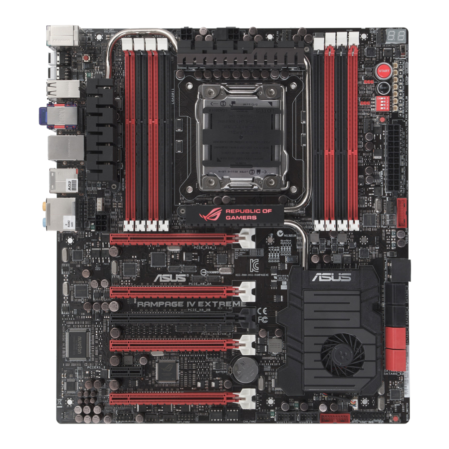
Page 26: Motherboard Overview
Motherboard overview 2.2.1 Motherboard layout Refer to 2.2.8 Internal connectors and 2.3.10 Rear panel connection for more information about rear panel connectors and internal connectors. Chapter 2: Hardware information…
-
Page 27: Layout Contents
Front panel audio connector (10-1 pin AAFP) 2-32 Digital audio connector (4-1 pin SPDIF_OUT) 2-30 EZ Plug connectors (6-pin EZ_PLUG_1; 4-pin EZ_PLUG_2) 2-34 OC Key connector (10-1 pin OC_KEY) 2-34 OT header (ROG Connect switch) 2-24 ROG RAMPAGE IV EXTREME…
-
Page 28: Central Processing Unit (Cpu)
Contact your retailer immediately if the PnP cap is missing, or if you see any damage to the PnP cap/socket contacts/motherboard components. ASUS will shoulder the cost of repair only if the damage is shipment/ transit-related.
-
Page 29: System Memory
The motherboard comes with four Double Data Rate 3 (DDR3) Dual Inline Memory Modules (DIMM) slots. A DDR3 module is notched differently from a DDR or DDR2 module. DO NOT install a DDR or DDR2 memory module to the DDR3 slot. Recommended memory configurations ROG RAMPAGE IV EXTREME…
-
Page 30: Memory Configurations
• According to Intel spec, the max. 64GB memory capacity can be supported with DIMMs of 8GB (or above). ASUS will update QVL once the DIMMs are available on the market. • According to Intel CPU spec, DIMM voltage below 1.65V is recommended to protect the CPU.
-
Page 31
RAMPAGE IV EXTREME Motherboard Qualified Vendors Lists (QVL) DDR3 2400 MHz capability DIMM socket support (Optional) Chip Chip Vendors Part No. Size Timing Voltage Brand 2 DIMM 4 DIMM 6 DIMM 8 DIMM A-DATA AX3U2400GC4G10(XMP) 10-11-10- 1.65 • • CORSAIR CMGTX3(XMP) 9-11-9-27 1.65… -
Page 32
RAMPAGE IV EXTREME Motherboard Qualified Vendors Lists (QVL) DDR3 2000 MHz capability Vendors Part No. Size Chip Chip NO. Timing Voltage DIMM socket support (Optional) Brand 2 DIMM 4 DIMM 6 DIMM 8 DIMM A-DATA AX3U2000GB2G9B(XMP) 9-11-9-27 1.55~1.75 • •… -
Page 33: 1800/1600 Mhz Capability
RAMPAGE IV EXTREME Motherboard Qualified Vendors Lists (QVL) DDR3 1800 MHz capability Vendors Part No. Size Chip Brand Chip NO. Timing Voltage DIMM socket support (Optional) 2 DIMM 4 DIMM 6 DIMM 8 DIMM G.SKILL F3-14400CL9D-4GBRL(XMP) 4GB(2 x DS — 9-9-9-24 1.6…
-
Page 34
( DDR3 1600 MHz continued ) Vendors Part No. Size Chip Brand Chip NO. Timing Voltage DIMM socket support (Optional) 2 DIMM 4 DIMM 6 DIMM 8 DIMM G.SKILL F3-12800CL9Q-16GBXL(XMP) 16GB ( 4x 9-9-9-24 • • • • 4GB ) G.SKILL F3-12800CL9D-4GBNQ(XMP) 4GB ( 2x… -
Page 35
4GB(2 x 7-7-7-20 • • 2GB) Patriot PX538G1600LLK(XMP) 8GB ( 2x 8-9-8-24 1.65 • • • 4GB ) Team TXD31024M1600C8-D(XMP) Team T3D1288RT-16 8-8-8-24 1.65 • • • Team TXD32048M1600HC8-D(XMP) Team T3D1288RT-16 8-8-8-24 1.65 • • • ROG RAMPAGE IV EXTREME 2-11… -
Page 36
RAMPAGE IV EXTREME Motherboard Qualified Vendors Lists (QVL) DDR3 1333 MHz capability Vendors Part No. Size Chip Brand Chip NO. Timing Voltage DIMM socket support (Optional) 2 DIMM 4 DIMM 6 DIMM 8 DIMM A-DATA AD63I1B0823EV A-DATA 3CCA-1509A • •… -
Page 37
• • • SAMSUNG M378B5273BH1-CH9 SAMSUNG K4B2G0846B-HCH9 • • • SAMSUNG M378B5273CH0-CH9 SAMSUNG K4B2G0846C K4B2G0846C — • • • SAMSUNG M378B5273DH0-CH9 SAMSUNG K4B2G08460 • • • ( DDR3 1333 MHz continues on next page ) ROG RAMPAGE IV EXTREME 2-13… -
Page 38
( DDR3 1333 MHz continued ) Vendors Part No. Size S S / Chip Brand Chip NO. Timing Voltage DIMM socket support (Optional) 2 DIMM 4 DIMM 6 DIMM 8 DIMM SAMSUNG M378B1G73AH0-CH9 SAMSUNG K4B4G0846A-HCH9 • • Transcend JM133 3KLN-2G (582670) Micron ICD77 C9LGK •… -
Page 39
RAMPAGE IV EXTREME Motherboard Qualified Vendors Lists (QVL) DDR3 1067 MHz capability Vendors Part No. Size Chip Brand Chip NO. Timing Voltage DIMM socket support (Optional) 2 DIMM 4 DIMM 6 DIMM 8 DIMM ELPIDA EBJ10UE8EDF0-AE-F ELPIDA J1108EDSE-DJ-F • ELPIDA… -
Page 40: Expansion Slots
2.2.4 Expansion slots Ensure to unplug the power cord before adding or removing expansion cards. Failure to do so may cause you physical injury and damage motherboard components. Slot No. Slot Description PCIe 3.0 x16_1 slot PCIe 3.0 x8_2A slot PCIe 3.0 x8_2B slot PCIe 3.0 x16/8_3 slot PCIe 2.0 x1_1 slot…
-
Page 41
– – – shared High Definition Audio – – – – – – shared – SATA #0 – – shared – – – – – SATA #0 – – – – shared – – – ROG RAMPAGE IV EXTREME 2-17… -
Page 42: Onboard Switches
2.2.5 Onboard switches Onboard switches allow you to fine-tune performance when working on a bare or open- case system. This is ideal for overclockers and gamers who continually change settings to enhance system performance. Power-on switch Press the power-on switch to wake/power up the system. Reset switch Press the reset switch to reboot the system.
-
Page 43
(GO_Button file) for temporary overclocking when in OS. BIOS button The motherboard comes with two BIOS. Press the BIOS button to switch BIOS and load different BIOS settings. The nearby BIOS LEDs indicate the BIOS you are using. ROG RAMPAGE IV EXTREME 2-19… -
Page 44
PCIe x16 Lane switch These slide switches allows you to enable and disable the corresponding PCIe x16 slots. When one of the installed PCIe x16 cards is out of order, you can use the slide switch to find out the faulty one without removing the cards. Q reset button When the LN2_Mode jumper does not work and your CPU cannot resume function, press the Q reset button to temporarily stop the power supply to the CPU and help the… -
Page 45
To over-come this simply flip the switch over to “slow” the processor instantaneously. Switching over to Slow-Mode during critical moments when Temperature/Max Frequency alignment is off-synch saves you a lot of crashes, even when trying to boot into the OS at cold temperatures. ROG RAMPAGE IV EXTREME 2-21… -
Page 46: Onboard Leds
2.2.6 Onboard LEDs The motherboard comes with a set of LEDs that indicate the voltage conditions of CPU, memory, northbridge and southbridge. You may adjust the voltages in BIOS. There are also an LED for hard disk drive activity and an onboard switch for power status. For more information about voltage adjustment, refer to 3.3 Extreme Tweaker menu.
-
Page 47
BIOS LED The BIOS LEDs help indicate the BIOS activity. Press the BIOS button to switch between BIOS1 and BIOS2 and the LED lights up when the corresponding BIOS is in use. ROG RAMPAGE IV EXTREME 2-23… -
Page 48
GO LED Blinking: Indicates that MemOK! is enabled before POST. Lighting: Indicates that the system loads the preset profile (GO_Button file) for temporary overclocking when in OS. Q LED Q LEDs check key components (CPU, DRAM, VGA card, and booting devices) in sequence during motherboard booting process. -
Page 49
The illustration below shows the location of the onboard power-on switch. Debug LEDs The Debug LED design provides you the 2-digit display, allowing you to know the system status. Refer to the Debug table below for details. ROG RAMPAGE IV EXTREME 2-25… -
Page 50: Debug Table
Debug table Code Description Not used Power on. Reset type detection (soft/hard). AP initialization before microcode loading System Agent initialization before microcode loading PCH initialization before microcode loading OEM initialization before microcode loading Microcode loading AP initialization after microcode loading System Agent initialization after microcode loading PCH initialization after microcode loading OEM initialization after microcode loading…
-
Page 51
CPU DXE initialization is started PCI host bridge initialization System Agent DXE initialization is started System Agent DXE SMM initialization is started 6B – 6F System Agent DXE initialization (System Agent module specific) PCH DXE initialization is started ROG RAMPAGE IV EXTREME 2-27… -
Page 52
Debug table (continued) Code Description PCH DXE SMM initialization is started PCH devices initialization 73 – 77 PCH DXE Initialization (PCH module specific) ACPI module initialization CSM initialization 7A – 7F Reserved for future AMI DXE codes 80 – 8F OEM DXE initialization codes Boot Device Selection (BDS) phase is started Driver connecting is started… -
Page 53: Asl Status Codes
System is waking up from the S3 sleep state System is waking up from the S4 sleep state System has transitioned into ACPI mode. Interrupt controller is in PIC mode System has transitioned into ACPI mode. Interrupt controller is in APIC mode ROG RAMPAGE IV EXTREME 2-29…
-
Page 54: Jumper
2.2.7 Jumper LN2 Mode Jumper (3-pin LN2) With LN2 mode activated, the ROG motherboard is optimized to remedy the cold- boot bug during POST at an extremely low temperature and help the system boot successfully. OT header (ROG Connect switch) The OT header allows connection of a 2-pin cable switch (purchased separately) for users to quickly enable/disable the OC Key feature without using the ROG Connect On/Off button on the rear I/O port.
-
Page 55: Internal Connectors
Before creating a RAID set, refer to section 4.4 RAID configurations or the manual bundled in the motherboard support DVD. • When using NCQ, set the SATA Mode in the BIOS to [AHCI Mode]. Refer to section 3.5.3 SATA Configuration for details. ROG RAMPAGE IV EXTREME 2-31…
-
Page 56
® Intel X79 Serial ATA 3.0 Gb/s connectors (7-pin SATA3G_1–4 [black]) These connectors connect to Serial ATA 3.0 Gb/s hard disk drives and optical disc drives via Serial ATA 3.0 Gb/s signal cables. If you installed Serial ATA hard disk drives, you can create a RAID 0, 1, 5, and 10 ®… -
Page 57
The Subzero Sense connector allows you to connect the K probe cable (purchased seperately) to measure the motherboard temperature via BIOS, OC Key or TurboV EVO without purchasing expensive multimeters. Subzero Sense detects the connector’s ambient temperature when it’s plugged. ROG RAMPAGE IV EXTREME 2-33… -
Page 58
USB 3.0 connector (20-1 pin USB3_56, USB3_78) This connector is for the additional USB 3.0 ports, and complies with the USB 3.0 specificaton that supports up to 4.8Gbps connection speed. If the USB 3.0 front panel cable is available from your system chassis, with this USB 3.0 connector, you can have a front panel USB 3.0 solution. -
Page 59
Never connect a 1394 cable to the USB connectors. Doing so will damage the motherboard! You can connect the front panel USB cable to the ASUS Q-Connector (USB, blue) first, and then install the Q-Connector (USB) to the USB connector onboard if your chassis supports front panel USB ports. -
Page 60
Digital audio connector (4-1 pin SPDIF_OUT) This connector is for an additional Sony/Philips Digital Interface (S/PDIF) port(s). Connect the S/PDIF Out module cable to this connector, then install the module to a slot opening at the back of the system chassis. The S/PDIF module is purchased separately. -
Page 61
The CPU_FAN connector supports the CPU fan of maximum 1A (12 W) fan power. • If you install two VGA cards, we recommend that you plug the rear chassis fan cable to the motherboard connector labeled CHA_FAN1 or CHA_FAN2 for better thermal environment. ROG RAMPAGE IV EXTREME 2-37… -
Page 62
Front panel audio connector (10-1 pin AAFP) This connector is for a chassis-mounted front panel audio I/O module that supports either HD Audio or legacy AC`97 audio standard. Connect one end of the front panel audio I/O module cable to this connector. •… -
Page 63
1000W power or above to ensure the system stability. • If you are uncertain about the minimum power supply requirement for your system, refer to the Recommended Power Supply Wattage Calculator at http://support.asus. com/PowerSupplyCalculator/PSCalculator.aspx?SLanguage=en-us for details. PSU Suggested List AcBel PC7030… -
Page 64
EZ Plug connectors (6-pin EZ_PLUG_1; 4-pin EZ_PLUG_2) The EZ Plug connectors provide additional power to the memory modules and PCI Express 3.0 x16 slots. Connect a 6-pin power cable to EZ_PLUG_1 when installing four PCIe3.0 x16 display cards to provide sufficient power supply. Connect a 4-pin power cable to EZ_PLUG_2 to provide stable power supply to the DIMMs. -
Page 65: System Panel Connector
Pressing the power switch for more than four seconds while the system is ON turns the system OFF. • Reset button (2-pin RESET) This 2-pin connector is for the chassis-mounted reset button for system reboot without turning off the system power. ROG RAMPAGE IV EXTREME 2-41…
-
Page 66: Building Your Computer System
Building your computer system 2.3.1 Additional tools and components to build a PC system 1 bag of screws Philips (cross) screwdriver PC chassis Power supply unit Intel LGA 2011 CPU Intel LGA 2011 compatible CPU Fan DIMM SATA hard disk drive SATA optical disc drive (optional) Graphics card (optional) The tools and components in the table above are not included in the motherboard package.
-
Page 67: Cpu Installation
Please note the order in opening/ closing the double latch. Follow the instructions printed on the metal sealing hatch or the illustrations shown below in this manual. The plastic cap will pop up automatically once the CPU is in place and the hatch properly sealed down. ROG RAMPAGE IV EXTREME 2-43…
-
Page 68
2-44 Chapter 2: Hardware information… -
Page 69: Cpu Heatsink And Fan Assembly Installation
2.3.3 CPU heatsink and fan assembly installation Apply the Thermal Interface Material to the CPU heatsink and CPU before you install the heatsink and fan if necessary. To install the CPU heatsink and fan assembly ROG RAMPAGE IV EXTREME 2-45…
-
Page 70
To replace the LGA2011 CPU pad (X-Socket) 2-46 Chapter 2: Hardware information… -
Page 71: Dimm Installation
2.3.4 DIMM installation To remove a DIMM ROG RAMPAGE IV EXTREME 2-47…
-
Page 72: Motherboard Installation
2.3.5 Motherboard installation The diagrams in this section are for reference only. The motherboard layout may vary with models, but the installation steps remain the same. 2-48 Chapter 2: Hardware information…
-
Page 73
DO NOT overtighten the screws! Doing so can damage the motherboard. ROG RAMPAGE IV EXTREME 2-49… -
Page 74: Atx Power Connection
2.3.6 ATX Power connection 2-50 Chapter 2: Hardware information…
-
Page 75: Sata Device Connection
2.3.7 SATA device connection ROG RAMPAGE IV EXTREME 2-51…
-
Page 76: Front I/O Connector
2.3.8 Front I/O Connector To install ASUS Q-Connector To install USB 2.0 Connector To install front panel audio connector AAFP USB 2.0 To install USB 3.0 Connector USB 3.0 2-52 Chapter 2: Hardware information…
-
Page 77: Expansion Card Installation
2.3.9 Expansion Card installation To install PCIe x16 cards To install PCIe x1 cards ROG RAMPAGE IV EXTREME 2-53…
-
Page 78: Rear Panel Connection
2.3.10 Rear panel connection Rear panel connectors 1. PS/2 mouse and keyboard port 2. USB 2.0 ports 7 and 8 3. Bluetooth module 4. LAN (RJ-45) port* 5. External SATA port 2 6. USB 2.0 ports 1 and 2 7. Clear CMOS switch 8.
-
Page 79
Line Out Front Speaker Out Front Speaker Out Front Speaker Out Pink Mic In Mic In Mic In Mic In Orange – – Center/Subwoofer Center/Subwoofer Black – Rear Speaker Out Rear Speaker Out Rear Speaker Out ROG RAMPAGE IV EXTREME 2-55… -
Page 80: Audio I/O Connections
2.3.11 Audio I/O connections Audio I/O ports Connect to Headphone and Mic Connect to Stereo Speakers Connect to 2.1 channel Speakers 2-56 Chapter 2: Hardware information…
-
Page 81
Connect to 4.1 channel Speakers Connect to 5.1 channel Speakers Connect to 7.1 channel Speakers ROG RAMPAGE IV EXTREME 2-57… -
Page 82: Oc Key Device Installation
2.3.12 OC Key device installation The OC Key device allows quick on-screen overclocking adjustments. Follow the instruction below to install the OC Key device to your system. To install the OC Key device Thread the OC Key cable through the opening on the I/O shield until the stopper on the cable snaps into place.
-
Page 83
Use the <Up>, <Down>, <Left> and <Right> to move the highlighted item, use the <Enter> key to enter an item, use the <ESC> key to exit an item, and use the <F10> key to save settings. ROG RAMPAGE IV EXTREME 2-59… -
Page 84
Key device and the other end of the cable to any USB port on the rear panel of the motherboard. Launch the firmware upgrade program downloaded from ASUS official website and follow screen intructions to update the OC Key device firmware. -
Page 85: Starting Up For The First Time
While the system is ON, pressing the power switch for less than four seconds puts the system on sleep mode or soft-off mode, depending on the BIOS setting. Pressing the power switch for more than four seconds lets the system enter the soft-off mode regardless of the BIOS setting. ROG RAMPAGE IV EXTREME 2-61…
-
Page 86
2-62 Chapter 2: Hardware information… -
Page 87: Chapter 3: Bios Setup
BIOS setup Knowing BIOS The new ASUS UEFI BIOS is an Unified Extensible Firmware Interface that complies with UEFI architecture, offering a user-friendly interface that goes beyond traditional keyboard- only BIOS controls to enable more flexible and convenient mouse input. Users can easily navigate the new UEFI BIOS with the same smoothness as their operating system.
-
Page 88: Advanced Mode
The Advanced Mode provides advanced options for experienced end-users to configure the BIOS settings. The figure below shows an example of the Advanced Mode. Refer to the following sections for the detailed configurations. To access the EZ Mode, click Exit, then select ASUS EZ Mode. Menu items Menu bar…
-
Page 89: Menu Items
You cannot select an item that is not user-configurable. A configurable field is highlighted when selected. To change the value of a field, select it and press <Enter> to display a list of options. ROG RAMPAGE IV EXTREME…
-
Page 90: Ez Mode
Power Saving mode Loads optimized default Displays the system properties of the Normal mode ASUS Optimal mode selected mode on the right hand side • The boot device options vary depending on the devices you installed to the system. •…
-
Page 91: Extreme Tweaker Menu
Be cautious when changing the settings of the Extreme Tweaker menu items. Incorrect field values can cause the system to malfunction. The configuration options for this section vary depending on the CPU and DIMM model you installed on the motherboard. Scroll down to display the following items: ROG RAMPAGE IV EXTREME…
-
Page 92
Scroll down to display the following items: Ai Overclock Tuner [Auto] Allows you to select the CPU overclocking options to achieve the desired CPU internal frequency. Select any of these preset overclocking configuration options: [Auto] Loads the optimal settings for the system. [Manual] Allows you to individually set overclocking parameters. -
Page 93: Dram Timing Control
<-> keys to adjust the value. To restore the default setting, type [auto] using the keyboard and press the <Enter> key. Changing the values in this menu may cause the system to become unstable! If this happens, revert to the default settings. ROG RAMPAGE IV EXTREME…
-
Page 94
Load Elipida Hyper Profile Change settings to suit Elpida Hyper Profile by selecting Yes. Load Tight PSC Profile Change settings to suit Tight PSC Profile by selecting Yes. Load Loose PSC Profile Change settings to suit Loose PSC Profile by selecting Yes. Load RAW MHZ Profile Change settings to suit RAW MHZ Profile by selecting Yes. -
Page 95
[Auto] Configuration options: [Auto] [0 DRAM Clock] – [7 DRAM Clock] tWRDD [Auto] Configuration options: [Auto] [0 DRAM Clock] – [7 DRAM Clock] tRWSR [Auto] Configuration options: [Auto] [0 DRAM Clock] – [15 DRAM Clock] ROG RAMPAGE IV EXTREME… -
Page 96
tCCD [Auto] Configuration options: [Auto] [0 DRAM Clock] – [7 DRAM Clock] Latency Timings DRAM RTL (CHA/B/C/D D0/1 R0/1 [Auto]) Configuration options: [Auto] [Advance 14 Clock] [Advance 12 Clock] – [Advance 4 Clock] [Advance 2 Clock] [Normal] [Delay 2 Clock] [Delay 4 Clock] – [Delay 12 Clock] [Delay 14 Clock] DRAM IOL (CHA/B/C/D D0/1 R0/1 [Auto]) Configuration options: [Auto] [Advance 14 Clock] –… -
Page 97
Reducing phase number under light system loading to increase VRM efficiency [Standard] Proceeds phase control depending on the CPU loading. [Optimized] Loads the ASUS optimized phase tuning profile. [Extreme] Proceeds the full phase mode. [Manual Adjustment] Allows manual adjustment. -
Page 98
Configuration options: [Auto] [manual] Configuration options: [Auto] [manual] DRAM-AB/DRAM-CD Power Phase control [Auto] [Optimized] Allows you to set ASUS optimized phase tuning profile. [Extreme] Allows you to set the Full phase mode. PCH 1.1V PCH 1.1v Switching Freq. [Auto] This item allows you to switch the frequency of PCH power. -
Page 99: Cpu Performance Settings
Use the <+> and <-> keys to adjust the value. Additional Turbo Voltage [Auto] Use the <+> and <-> keys to adjust the value. CPU Core Current Limit [Auto] Use the <+> and <-> keys to adjust the value. ROG RAMPAGE IV EXTREME 3-13…
-
Page 100
GPU/DIMM Post GPU Post The GPU Post sub-menu allows you to view the information of individual PCI Express slots. PCIe Lane Simulator The PCIe Lane Simulator item allows you to simulate PCIe lane arrangement. DIMM Post The DIMM Post sub-menu allows you to view the information of installed DIMMs. Extreme OV [Disable] This item is set to [Disabled] by default to protect the CPU from being overheated. -
Page 101
Allows you to set the CPU PLL voltage. The values range from 1.2500V to 2.5000V with a 0.00625V interval. PCH 1.1v Voltage [Auto] Allows you to set the 1.1v Platform Controller Hub voltage. The values range from 0.8000V to 1.6000V with a 0.00625V interval. ROG RAMPAGE IV EXTREME 3-15… -
Page 102
VTTDDR Voltage (CHA, CHB) [Auto] Allows you to set the VTTDDR voltage for DRAM channel A and B. The values range from for DRAM channel A and B. The values range from . The values range from 0.6250V to 1.1000V with a 0.00625V interval. VTTDDR Voltage (CHC, CHD) [Auto] Allows you to set the VTTDDR voltage for DRAM channel C and D. -
Page 103
DRAM DATA REF Voltage on CHA/B/C/D The values range from 0.3950x to 0.6300x with a 0.0050x interval. DRAM Read REF Voltage on CHA/B/C/D The values range from 0.38500x to 0.61500x with a 0.0050x interval. PCH Chipset Tweakers’ Paradise ROG RAMPAGE IV EXTREME 3-17… -
Page 104
PCH 1.5v Voltage [Auto] The values range from 1.2000V to 2.3000V with a 0.00625V interval. PCH Logic Reference (1.1VG) [Auto] The values range from 0.80642V to 1.60623V with a 0.00661V interval. PCH DMI Strength [Auto] Configuration options: [-96] – [-1] [Auto] [+1] – [+96] PCH DMI Skew [Auto] Configuration options: [-96] –… -
Page 105: Main Menu
System Language [English] Allows you to choose the BIOS language version from the options. 3.4.2 System Date [Day xx/xx/xxxx] Allows you to set the system date. 3.4.3 System Time [xx:xx:xx] Allows you to set the system time. ROG RAMPAGE IV EXTREME 3-19…
-
Page 106: Security
3.4.4 Security The Security menu items allow you to change the system security settings. • If you have forgotten your BIOS password, erase the CMOS Real Time Clock (RTC) RAM to clear the BIOS password. See section 2.3.10 Rear panel connection for information on how to erase the RTC RAM.
-
Page 107: User Password
To clear the user password, follow the same steps as in changing a user password, but press <Enter> when prompted to create/confirm the password. After you clear the password, the User Password item on top of the screen shows Not Installed. ROG RAMPAGE IV EXTREME 3-21…
-
Page 108: Advanced Menu
Advanced menu The Advanced menu items allow you to change the settings for the CPU and other system devices. Be cautious when changing the settings of the Advanced menu items. Incorrect field values can cause the system to malfunction. 3-22 Chapter 3: BIOS setup…
-
Page 109: Cpu Configuration
[Enabled] Two threads per activated core are enabled. Active Processor Cores [All] Allows you to choose the number of CPU cores to activate in each processor package. Configuration options: [All] [1] [2] [3] [4] [5] ROG RAMPAGE IV EXTREME 3-23…
-
Page 110
Limit CPUID Maximum [Disabled] [Enabled] Allows legacy operating systems to boot even without support for CPUs with extended CPUID functions. [Disabled] Disables this function. Execute Disable Bit [Enabled] [Enabled] Enables the No-Execution Page Protection Technology. [Disabled] Forces the XD feature flag to always return to zero (0). Intel Virtualization Tech [Enabled] [Enabled] Allows a hardware platform to run multiple operating systems separately… -
Page 111: Pch Configuration
[RAID Mode] Set to [RAID Mode] when you want to create a RAID configuration from the SATA hard disk drives. ROG RAMPAGE IV EXTREME 3-25…
-
Page 112
The following two items appear only when you set the SATA Mode item to [IDE Mode]. Serial-ATA Controller 0 [Enabled] Allows you to enabled/disabled the Serial-ATA Controller 0. Configuration options: [Disabled] [Enabled] [Compatible] Serial-ATA Controller 1 [Enabled] Allows you to enabled/disabled the Serial-ATA Controller 1. Configuration options: [Disabled] [Enabled] S.M.A.R.T. -
Page 113: Usb Configuration
Disables the function. [Enabled] Enables the support for USB 3.0 devices on legacy operating systems (OS). EHCI Hand-off [Disabled] [Disabled] Disables the function. [Enabled] Enables the support for operating systems without an EHCI hand-off feature. ROG RAMPAGE IV EXTREME 3-27…
-
Page 114: Onboard Devices Configuraton
3.5.5 Onboard Devices Configuraton Azalia HD Audio [Enabled] [Disabled] Disables the controller. [Enabled] Enables the High Definition Audio Controller. The following two items appear only when you set the Azalia HD Audio item to [Enabled]. Front Panel Type [HD] Allows you to set the front panel audio connector (AAFP) mode to legacy AC97 or high- definition audio depending on the audio standard that the front panel audio module supports.
-
Page 115
ASM1061 Storage OPROM [Enabled] This item appears only when you set the previous item to [IDE Mode] or [AHCI Mode] and allows you to enable or disable the OptionRom of the ASM1061 storage controller. Configuration options: [Disabled] [Enabled] ROG RAMPAGE IV EXTREME 3-29… -
Page 116: Apm
3.5.6 Restore AC Power Loss [Power Off] [Power On] The system goes into on state after an AC power loss. [Power Off] The system goes into off state after an AC power loss. [Last State] The system goes into either off or on state, whatever the system state was before the AC power loss.
-
Page 117: Monitor Menu
CPU Temperature; MB Temperature; PCH Temperature; OPT1/2/3 Temperature[xxxºC/ xxxºF] The onboard hardware monitor automatically detects and displays the CPU, motherboard, and the assigned devices temperatures. Select [Ignored] if you do not wish to display the detected temperatures. ROG RAMPAGE IV EXTREME 3-31…
-
Page 118: Fan Speed Control
Fan Speed Monitor CPU FAN Speed; CPU OPT Speed; Chassis FAN1/2/3 Speed; PCH FAN Speed; OPT FAN 1/2/3 Speed [xxxxRPM] or [Ignored] / [N/A] The onboard hardware monitor automatically detects and displays the CPU fan, chassis fan, PCH fan, and optional fan speed in rotations per minute (RPM). If any of the fans is not connected to the motherboard, the field shows [N/A].
-
Page 119
Use the <+> and <-> keys to adjust the minimum chassis fan duty cycle. The values range from 0% to 100%. When the chassis temperature is under 40ºC, the chassis fan will operate at the minimum duty cycle. ROG RAMPAGE IV EXTREME 3-33… -
Page 120
PCH Fan Control [Disabled] Allows you to select the PCH fan control mode. When this item is set to [Duty Mode], you can configure the PCH Fan. Duty Cycle() item. When this item is set to [Profile Mode], you can configure the PCH Fan Profile item. -
Page 121: Boot Menu
Full Screen Logo [Enabled] [Enabled] Enables the full screen logo display feature. [Disabled] Disables the full screen logo display feature. Set this item to [Enabled] to use the ASUS MyLogo 2™ feature. Wait For ‘F1’ If Error [Enabled] [Disabled] Disables this function. [Enabled] The system waits for the <F1>…
-
Page 122: Boot Option Priorities
• To select the boot device during system startup, press <F8> when ASUS Logo appears. • To access Windows OS in Safe Mode, press <F8> after POST.
-
Page 123: Tools Menu
<Enter> to display the submenu. 3.8.1 ASUS EZ Flash Utility Allows you to run ASUS EZ Flash Utility. When you press <Enter> to start the application. For more details, refer to section 3.10.2 ASUS EZ Flash Utility. ROG RAMPAGE IV EXTREME…
-
Page 124: Asus O.c. Profile
3.8.2 ASUS O.C. Profile This item allows you to store or load multiple BIOS settings. The Setup Profile Status items show Not Installed if no profile is created. Label Allows you to input the label of setup profile. Save to Profile Allows you to save the current BIOS settings to the BIOS Flash, and create a profile.
-
Page 125: Bios Flashback
Allows you to boot the system using BIOS chip 2. COPY BIOS1 to BIOS2 Only current operating BIOS can be mirrored. System will enter the soft-off state. After BIOS backup is finished, system will auto power-on. ROG RAMPAGE IV EXTREME 3-39…
-
Page 126: Go Button File
3.8.4 GO Button File This menu allows you to set the GO Button files, and load the desired GO Button file. Scroll down to display the following items: BCLK Frequency; CPU Ratio; CPU Voltage; CPU VCCSA Voltage; DRAM Voltage (CHA, CHB/CHC, CHD); CPU PLL Voltage; VTT CPU Voltage; PCH 1.1v Voltage;…
-
Page 127: Exit Menu
This option allows you to enter the EZ Mode screen. Launch EFI Shell from filesystem device This option allows you to attempt to launch the EFI Shell application (shellx64.efi) from one of the available filesystem devices. ROG RAMPAGE IV EXTREME 3-41…
-
Page 128: Updating Bios
BIOS in the future. Copy the original motherboard BIOS using the ASUS Update or BIOS Updater utilities. 3.10.1 ASUS Update utility The ASUS Update is a utility that allows you to manage, save, and update the motherboard BIOS in Windows environment. The ASUS Update utility allows you to: ®…
-
Page 129
To update the BIOS through the Internet: From the ASUS Update screen, select Update BIOS from Internet, and then click Next. Select the ASUS FTP site nearest you to avoid network traffic. If you want to enable the BIOS downgradable function and auto BIOS backup function, check the checkboxs before the two items on the screen. -
Page 130
Click Browse to locate your desired picture file. Adjust the picture resolution if needed and click Next to continue. Follow the onscreen instructions to complete the update process. 3-44 Chapter 3: BIOS setup… -
Page 131
The screenshots in this section are for reference only. The actual BIOS information vary by models. • Refer to the software manual in the support DVD or visit the ASUS website at www. asus.com for detailed software configuration. ROG RAMPAGE IV EXTREME… -
Page 132: Asus Ez Flash Utility
3.10.2 ASUS EZ Flash Utility The ASUS EZ Flash Utility feature allows you to update the BIOS without having to use a bootable floppy disk or an OS-based utility. Before you start using this utility, download the latest BIOS from the ASUS website at www.
-
Page 133: Asus Crashfree Bios 3 Utility
The BIOS file in the motherboard support DVD may be older than the BIOS file published on the ASUS official website. If you want to use the newer BIOS file, download the file at support.asus.com and save it to a USB flash drive.
-
Page 134: Asus Bios Updater
3.10.4 ASUS BIOS Updater The ASUS BIOS Updater allows you to update BIOS in DOS environment. This utility also allows you to copy the current BIOS file that you can use as a backup when the BIOS fails or gets corrupted during the updating process.
-
Page 135
The BIOS Updater backup screen appears indicating the BIOS backup process. When BIOS backup is done, press any key to return to the DOS prompt. ASUSTek BIOS Updater for DOS V1.18 [2010/04/29] Current ROM Update ROM BOARD: RAMPAGE IV EXTREME BOARD: Unknown VER: 0211 VER: Unknown DATE: 09/05/2011 DATE: Unknown PATH: A: BIOS backup is done! Press any key to continue. Note Saving BIOS: ROG RAMPAGE IV EXTREME 3-49… -
Page 136
Updating the BIOS file To update the BIOS file using BIOS Updater At the FreeDOS prompt, type bupdater /pc /g and press <Enter>. D:>bupdater /pc /g The BIOS Updater screen appears as below. ASUSTek BIOS Updater for DOS V1.18 [2010/04/29] Current ROM Update ROM BOARD: BOARD: Unknown RAMPAGE IV EXTREME VER: Unknown VER: 0211 DATE: Unknown DATE: 09/05/2011 PATH: A: R4E.ROM 4194304 2010-08-05 17:30:48 Note [Enter] Select or Load [Tab] Switch [V] Drive Info… -
Page 137: Usb Bios Flashback
The USB BIOS Flashback allows users to update BIOS without entering BIOS or the operating system by using a USB flash disk drive under standby power. Download the latest BIOS program file from the ASUS website. Extract and rename the BIOS image file to R4E.ROM.
-
Page 138: Chapter 4: Software Support
The contents of the support DVD are subject to change at any time without notice. Visit the ASUS website at www.asus.com for updates. 4.2.1 Running the support DVD Place the support DVD into the optical drive.
-
Page 139: Obtaining The Software Manuals
® Acrobat Reader from the Utilities menu before opening the files. ® Click on the Manual tab. Click on ASUS Motherboard Utility Guide from the manual list on the left. The Manual folder of the support DVD appears. Double-click the folder of your selected software.
-
Page 140: Software Information
4.3.1 AI Suite II AI Suite II is an all-in-one interface that integrates several ASUS utilities and allows users to launch and operate these utilities simultaneously. Installing AI Suite II To install AI Suite II on your computer Place the support DVD to the optical drive.
-
Page 141: Turbov Evo
After installing AI Suite II from the motherboard support DVD, launch TurboV EVO by clicking Tool > TurboV EVO on the AI Suite II main menu bar. Refer to the software manual in the support DVD or visit the ASUS website at www.asus.com for detailed software configuration.
-
Page 142
Set the CPU Ratio Setting item in BIOS to [Auto] before using the CPU Ratio function • in TurboV. Refer to Chapter 3 of your motherboard user manual for details. • The CPU Ratio bars show the status of the CPU cores, which vary with your CPU model. ROG RAMPAGE IV EXTREME… -
Page 143: Auto Tuning
• The value on the CPU Strap diagram varies with your CPU model. Auto Tuning ASUS TurboV EVO includes two auto tuning modes, providing the most flexible auto-tuning options. • The overclocking result varies with the CPU model and the system configuration.
-
Page 144
Click Stop if you want to cancel the Overclocking process. TurboV EVO automatically adjusts and saves BIOS settings and restarts the system. After re-entering Windows, a message appears indicating auto tuning success. Click OK to exit. ROG RAMPAGE IV EXTREME… -
Page 145: Digi+ Power Control
4.3.3 DIGI+ Power Control DIGI+ PowerControl allows you to adjust VRM voltage and frequency modulation to enhance reliability and stability. It also provides the highest power efficiency, generating less heat to longer component lifespan and minimize power loss. After installing AI Suite II from the motherboard support DVD, launch DIGI+ Power Control by clicking Tool >…
-
Page 146
Set Manual Adjustment to faster phase response to increase system performance or to slower phase response to increase DRAM power efficiency. • The actual performance boost may vary depending on your CPU specification. • Do not remove the thermal module. The thermal conditions should be monitored. ROG RAMPAGE IV EXTREME… -
Page 147: Epu
Select From the Last Reset to show the total CO2 that has been reduced since you click the Clear button • Refer to the software manual in the support DVD or visit the ASUS website at www.asus.com for detailed software configuration. 4-10…
-
Page 148: Fan Xpert
However, the fan will speed up when the temperature exceeds 70°C. • User: Allows you to configure the CPU fan profile under certain limitations. Refer to the software manual in the support DVD or visit the ASUS website at www.asus.com for detailed software configuration. ROG RAMPAGE IV EXTREME…
-
Page 149: Sensor Recorder
4.3.6 Sensor Recorder Sensor Recorder monitors the changes in the system voltage, temperature, and fan speed on a timeline. The History Record function allows you to designate specific time spans on record to keep track of the three system statuses for certain purposes. Launching Sensor Recorder After installing AI Suite II from the motherboard support DVD, launch Sensor Recorder by clicking Tool >…
-
Page 150: Probe Ii
Loads your saved Applies your Loads the default configuration changes threshold values for each sensor Refer to the software manual in the support DVD or visit the ASUS website at www.asus.com for detailed software configuration. ROG RAMPAGE IV EXTREME 4-13…
-
Page 151: Usb 3.0 Boost
4.3.8 USB 3.0 Boost The ASUS exclusive USB 3.0 Boost provides speed boost for USB 3.0 devices and the up-to-date support of USB Attached SCSI Protocol (UASP). With USB 3.0 Boost, you can accelerate the transfer speed of your USB 3.0 devices with ease.
-
Page 152: Ai Charger
* Check your USB device manufacturer if it fully supports the BC 1.1 function. • ** The actual charging speed may vary with your USB device’s conditions. • Ensure to remove and reconnect your USB device after enabling or disabling Ai Charger+ to ensure normal charging function. ROG RAMPAGE IV EXTREME 4-15…
-
Page 153: Asus Update
4.3.10 ASUS Update ASUS Update lays out the options for updating BIOS on your system. Update BIOS utility on your system or simply save the utility for later use just by following the directions on this convenient updating feature. Launching ASUS Update After installing AI Suite II from the motherboard support DVD, launch ASUS Update by clicking Update>…
-
Page 154: Mylogo2
Select the way you would like to do update your boot logo. Then click Next and follow the given instructions. Change the BIOS boot logo of my motherboard Under Current BIOS, click Browse and choose the desired image for your boot logo. Then click on Next. ROG RAMPAGE IV EXTREME 4-17…
-
Page 155
Click on Auto Tune to adjust image size compatibility or adjust the resolution bar. You can click on Booting Preview to preview the boot image. Then click Next. Click on Flash to start updating the image to the boot logo. Click on Yes to reboot or you can also see the new logo next time you restart your computer. -
Page 156: Rog Connect
PC and the remote PC. Press the ROG Connect Button. Double-click the RC TweakIt shortcut on the remote PC to activate the function Using RC TweakIt Use the sliders and buttons to monitor or adjust your local PC. ROG RAMPAGE IV EXTREME 4-19…
-
Page 157
Click Function to display more options. RC Poster RC Poster shows the status of the local system during the POST. You can switch the display mode between String and Code. RC Remote RC Remote allows you to operate your local system through the ROG Connect cable. -
Page 158
GPU TweakIt GPU TweakIt allows you to control and monitor the installed GPU on the local system. Use the sliders to adjust the values and click Apply to save your customized settings. ROG RAMPAGE IV EXTREME 4-21… -
Page 159: Audio Configurations
Realtek HD Audio Manager for Windows XP Exit button Configuration options Minimize button Control settings window Information button Refer to the software manual in the support DVD or visit the ASUS website at www.asus.com for detailed software configuration. 4-22 Chapter 4: Software support…
-
Page 160: Raid Configurations
With the RAID 10 configuration you get all the benefits of both RAID 0 and RAID 1 configurations. Use four new hard disk drives or use an existing drive and three new drives for this setup. ROG RAMPAGE IV EXTREME 4-23…
-
Page 161: Installing Serial Ata Hard Disks
4.4.2 Installing Serial ATA hard disks The motherboard supports Serial ATA hard disk drives. For optimal performance, install identical drives of the same model and capacity when creating a disk array. To install the SATA hard disks for a RAID configuration: Install the SATA hard disks into the drive bays.
-
Page 162: Creating A Raid Set
When the Disks item is selected, press <Enter> to select the hard disk drives you want to include in the RAID set. The SELECT DISKS screen appears: [ SELECT DISKS ] Port Drive Model Serial # Size Status 0 ST3160812AS 9LS0HJA4 149.0GB Non-RAID Disk 1 ST3160812AS 9LS0F4HL 149.0GB Non-RAID Disk 2 ST3160812AS 3LS0JYL8 149.0GB Non-RAID Disk 3 ST3160812AS 9LS0BJ5H 149.0GB Non-RAID Disk Select 2 to 6 disks to use in creating the volume. [ ↑↓ ]-Prev/Next [SPACE]-SelectDisk [ENTER]-Done ROG RAMPAGE IV EXTREME 4-25…
-
Page 163
Use the up/down arrow key to select a drive, and then press <Space> to select. A small triangle marks the selected drive. Press <Enter> after completing your selection. Use the up/down arrow key to select the stripe size for the RAID array (for RAID 0, 10 and 5 only),and then press <Enter>. -
Page 164
To exit the utility: From the utility main menu, select 5. Exit, and then press <Enter>. The following warning message appears: [ CONFIRM EXIT ] Are you sure you want to exit? (Y/N): Press <Y> to exit or press <N> to return to the utility main menu. ROG RAMPAGE IV EXTREME 4-27… -
Page 165: Creating A Raid Driver Disk
Launch Windows File Manager and locate the following path in the support DVD: DriversRAIDRSTeDriver Double-click AsMakeDisk.exe to launch the ASUS MakeDisk Utility. Select the USB floppy disk drive as the destination disk. Follow the succeeding screen instructions to complete the process.
-
Page 166: Installing The Raid Driver During Windows ® Os Installation
Follow the succeeding screen instructions to complete the installation. Before loading the RAID driver from a USB flash drive, you have to use another computer to copy the RAID driver from the support DVD to the USB flash drive. ROG RAMPAGE IV EXTREME 4-29…
-
Page 167: Using A Usb Floppy Disk Drive
4.5.4 Using a USB floppy disk drive Due to OS limitation, Windows XP may not recognize the USB floppy disk drive when you ® install the RAID driver from a floppy disk during the OS installation. To solve this issue, add the USB floppy disk drive’s Vendor ID (VID) and Product ID (PID) to the floppy disk containing the RAID driver.
-
Page 168
Type the following line to the bottom of the two sections: id = “USBVID_xxxx&PID_xxxx”, “usbstor” [HardwareIds.scsi.iaAHCI_DesktopWorkstationServer] id= “PCIVEN_8086&DEV_1C02&CC_0106”,”iaStor” id= “USBVID_03EE&PID_6901”, “usbstor” [HardwareIds.scsi.iaStor_DesktopWorkstationServer] id= “PCIVEN_8086&DEV_2822&CC_0104”,”iaStor” id= “USBVID_03EE&PID_6901”, “usbstor” Add the same line to both sections. The VID and PID vary with different vendors. Save and exit the file. ROG RAMPAGE IV EXTREME 4-31… -
Page 169
4-32 Chapter 4: Software support… -
Page 170: Chapter 5: Multiple Gpu Technology Support
For Windows XP, go to Control Panel > Add/Remove Programs. For Windows Vista, go to Control Panel > Programs and Features. Select your current graphics card driver/s. For Windows XP, select Add/Remove. For Windows Vista, select Uninstall. Turn off your computer. ROG RAMPAGE IV EXTREME…
-
Page 171: Installing Two Crossfirex™ Graphics Cards
5.1.3 Installing two CrossFireX™ graphics cards The following pictures are for reference only. The graphics cards and the motherboard layout may vary with models, but the installation steps remain the same. Prepare two CrossFireX-ready graphics cards. Insert the two graphics card into the PCIEX16 slots.
-
Page 172: Installing The Device Drivers
Graphics Settings > Performance > AMD CrossFireX Configuration. From the Graphics Adapter list, select the graphics card to act as the display GPU. Select Enable CrossFireX Click Apply, and then click OK to exit the window. ROG RAMPAGE IV EXTREME…
-
Page 173: Nvidia ® Sli™ Technology
NVIDIA SLI™ technology ® The motherboard supports the NVIDIA SLI™ (Scalable Link Interface) technology that ® allows you to install multi-graphics processing units (GPU) graphics cards. Follow the installation procedures in this section. 5.2.1 Requirements • In SLI mode, you should have two identical SLI-ready graphics cards that are NVIDIA ®…
-
Page 174: Installing The Device Drivers
You can launch the NVIDIA Control Panel by the following two methods. Right click on the empty space of the Windows desktop ® and select NVIDIA Control Panel. The NVIDIA Control Panel window appears (See Step B5). ROG RAMPAGE IV EXTREME…
-
Page 175
If you cannot see the NVIDIA Control Panel item in step (A), select Personalize. From the Personalization window, select Display Settings. From the Display Settings dialog box, click Advanced Settings. Chapter 5: Multiple GPU technology support… -
Page 176
Panel. The NVIDIA Control Panel window appears. Enabling SLI settings From the NVIDIA Control Panel window, select Set SLI Configuration. Click Enable SLI and set the display for viewing SLI rendered content. When done, click Apply. ROG RAMPAGE IV EXTREME… -
Page 177
Chapter 5: Multiple GPU technology support… -
Page 178: Asus Contact Information
+1-812-282-3777 +1-510-608-4555 Web site usa.asus.com Technical Support Telephone +1-812-282-2787 Support fax +1-812-284-0883 Online support support.asus.com ASUS COMPUTER GmbH (Germany and Austria) Address Harkort Str. 21-23, D-40880 Ratingen, Germany +49-2102-959911 Web site www.asus.de Online contact www.asus.de/sales Technical Support Telephone (Component) +49-1805-010923*…
- Manuals
- Brands
- Asus Manuals
- Software
- Rampage IV Extreme
Manuals and User Guides for Asus Rampage IV Extreme. We have 3 Asus Rampage IV Extreme manuals available for free PDF download: User Manual, Bedienungsanleitung
Asus Rampage IV Extreme User Manual (179 pages)
Intel X79 Express Chipset
Brand: Asus
|
Category: Motherboard
|
Size: 11.74 MB
Table of Contents
-
Table of Contents
3
-
Contents
4
-
Notices
7
-
Federal Communications Commission Statement
7
-
FCC Radio Frequency (RF) Exposure Caution Statement
7
-
Declaration of Conformity (R&TTE Directive 1999/5/EC)
8
-
CE Mark Warning
8
-
Wireless Operation Channel for Different Domains
9
-
France Restricted Wireless Frequency Bands
9
-
Canadian Department of Communications Statement
10
-
IC Radiation Exposure Statement for Canada
10
-
-
Safety Information
11
-
Electrical Safety
11
-
Operation Safety
12
-
Reach
12
-
-
About this Guide
13
-
How this Guide Is Organized
13
-
Where to Find more Information
13
-
Conventions Used in this Guide
14
-
Typography
14
-
-
RAMPAGE IV EXTREME Specifications Summary
15
-
Chapter 1: Product Introduction
19
-
Welcome
19
-
Package Contents
19
-
Special Features
20
-
Product Highlights
20
-
ROG Intelligent Performance & Overclocking Features
21
-
Bios Flashback
22
-
Sound with Clarity
23
-
ROG EZ DIY Features
24
-
Software Bundled
24
-
-
-
Chapter 2: Hardware Information
25
-
Before You Proceed
25
-
Motherboard Overview
26
-
Motherboard Layout
26
-
Layout Contents
27
-
Central Processing Unit (CPU)
28
-
System Memory
29
-
Memory Configurations
30
-
1800/1600 Mhz Capability
33
-
-
Expansion Slots
40
-
Onboard Switches
42
-
Onboard Leds
46
-
Debug Table
50
-
Asl Status Codes
53
-
-
Jumper
54
-
Internal Connectors
55
-
System Panel Connector
65
-
-
Building Your Computer System
66
-
Additional Tools and Components to Build a PC System
66
-
CPU Installation
67
-
CPU Heatsink and Fan Assembly Installation
69
-
DIMM Installation
71
-
Motherboard Installation
72
-
ATX Power Connection
74
-
SATA Device Connection
75
-
Front I/O Connector
76
-
Expansion Card Installation
77
-
Rear Panel Connection
78
-
Audio I/O Connections
80
-
OC Key Device Installation
82
-
-
Starting up for the First Time
85
-
Turning off the Computer
85
-
-
Chapter 3: BIOS Setup
87
-
Knowing BIOS
87
-
BIOS Setup Program
87
-
Advanced Mode
88
-
Menu Items
89
-
Submenu Items
89
-
Scroll Bar
89
-
Navigation Keys
89
-
General Help
89
-
Configuration Fields
89
-
-
EZ Mode
90
-
-
Extreme Tweaker Menu
91
-
Dram Timing Control
93
-
Cpu Performance Settings
99
-
-
Main Menu
105
-
System Language [English]
105
-
System Date [Day XX/XX/XXXX]
105
-
System Time [XX:XX:XX]
105
-
Security
106
-
User Password
107
-
-
Advanced Menu
108
-
CPU Configuration
109
-
PCH Configuration
111
-
SATA Configuration
111
-
USB Configuration
113
-
Onboard Devices Configuraton
114
-
Apm
116
-
-
Monitor Menu
117
-
Fan Speed Control
118
-
Boot Menu
121
-
Boot Option Priorities
122
-
Boot Override
122
-
-
Tools Menu
123
-
ASUS EZ Flash Utility
123
-
ASUS O.C. Profile
124
-
BIOS Flashback
125
-
GO Button File
126
-
-
Exit Menu
127
-
Updating BIOS
128
-
ASUS Update Utility
128
-
ASUS EZ Flash Utility
132
-
ASUS Crashfree BIOS 3 Utility
133
-
ASUS BIOS Updater
134
-
USB BIOS Flashback
137
-
-
-
Chapter 4: Software Support
138
-
Installing an Operating System
138
-
Support DVD Information
138
-
Running the Support DVD
138
-
Obtaining the Software Manuals
139
-
-
Software Information
140
-
AI Suite II
140
-
Turbov EVO
141
-
Auto Tuning
143
-
DIGI+ Power Control
145
-
Epu
147
-
Launching Epu
147
-
FAN Xpert
148
-
Sensor Recorder
149
-
Probe II
150
-
USB 3.0 Boost
151
-
Ai Charger
152
-
ASUS Update
153
-
Mylogo2
154
-
ROG Connect
156
-
Audio Configurations
159
-
-
RAID Configurations
160
-
RAID Definitions
160
-
Installing Serial ATA Hard Disks
161
-
Setting the RAID Item in BIOS
161
-
Intel ® Rapid Storage Technology Option ROM Utility
161
-
Creating a Raid Set
162
-
-
Creating a RAID Driver Disk
165
-
Creating a RAID Driver Disk Without Entering the os
165
-
Creating a RAID Driver Disk in Windows
165
-
Installing the RAID Driver During Windows ® os Installation
166
-
Using a USB Floppy Disk Drive
167
-
-
-
Chapter 5: Multiple GPU Technology Support
170
-
AMD ® Crossfirex™ Technology
170
-
Requirements
170
-
Before You Begin
170
-
Installing Two Crossfirex™ Graphics Cards
171
-
Installing the Device Drivers
172
-
Enabling the AMD ® Crossfirex™ Technology
172
-
-
NVIDIA ® SLI™ Technology
173
-
Requirements
173
-
Installing Two SLI-Ready Graphics Cards
173
-
Installing the Device Drivers
174
-
Enabling the NVIDIA ® SLI™ Technology
174
-
Asus Contact Information
178
-
-
Advertisement
Asus Rampage IV Extreme User Manual (22 pages)
Brand: Asus
|
Category: Software
|
Size: 4.14 MB
Table of Contents
-
Table of Contents
1
-
AI Suite II
2
-
Installing AI Suite II
2
-
Using AI Suite II
2
-
-
Turbov EVO
3
-
Turbov
3
-
Using Advanced Mode
4
-
CPU Ratio
4
-
-
CPU Level up
5
-
CPU Strap
5
-
-
New DIGI+ Power Control
7
-
Epu
9
-
Launching EPU
9
-
-
FAN Xpert
10
-
Launching FAN Xpert
10
-
Using FAN Xpert
10
-
Fan Setting
10
-
-
Probe II
11
-
Launching Probe II
11
-
Configuring Probe II
11
-
-
Sensor Recorder
15
-
Launching Sensor Recorder
15
-
Using Sensor Recorder
15
-
Using History Record
15
-
-
USB 3.0 Boost
16
-
Launching USB 3.0 Boost
16
-
Configuring USB 3.0 Boost
16
-
-
Ai Charger
17
-
Monitor
18
-
Sensor
18
-
CPU Frequency
18
-
-
ASUS Update
19
-
Launching ASUS Update
19
-
Using ASUS Update
19
-
-
Mylogo2
20
-
Launching ASUS Update
20
-
Using Mylogo
20
-
-
System Information
22

(German) Asus Rampage IV Extreme Bedienungsanleitung (172 pages)
Brand: Asus
|
Category: Motherboard
|
Size: 22.65 MB
Table of Contents
-
Table of Contents
3
-
Erklärungen
6
-
Sicherheitsinformationen
10
-
Über dieses Handbuch
12
-
RAMPAGE IV EXTREME Spezifikationsübersicht
14
-
Kapitel 1 : Produkteinführung
19
-
Willkommen
19
-
Paketinhalt
19
-
Sonderfunktionen
20
-
Leistungsmerkmale des Produkts
20
-
Intelligente ROG Leistungs- und Übertaktungsfunktionen
21
-
Kristallklarer Sound
23
-
ROG EZ DIY Features
24
-
Beigelegte Software
24
-
-
-
Kapitel 2 : Hardware- Beschreibungen
25
-
Bevor Sie Beginnen
25
-
Motherboard-Übersicht
26
-
Motherboard-Layout
26
-
Zentralverarbeitungseinheit (CPU)
28
-
Systemspeicher
29
-
Erweiterungssteckplätze
34
-
Onboard-Schalter
36
-
Onboard Leds
40
-
Jumper
48
-
Interne Anschlüsse
49
-
-
Aufbau des Computersystems
60
-
Zusatzwerkzeug und Komponenten für den PC-Aufbau
60
-
Installieren der CPU
61
-
Installieren von CPU-Kühlkörper und Lüfter
63
-
Installieren eines Dimms
65
-
Motherboard-Installation
66
-
ATX-Netzteilanschluss
68
-
SATA-Gerätanschlüsse
69
-
E/A-Anschlüsse auf der Vorderseite
70
-
Erweiterungskarten
71
-
Rücktafelanschlüsse
72
-
Audio E/A-Verbindungen
74
-
OC Key-Geräteinstallation
76
-
-
Erstmaliges Starten
79
-
Ausschalten des Computers
79
-
-
Kapitel 3: BIOS-Setup
81
-
Kennenlernen des BIOS
81
-
BIOS-Setupprogramm
81
-
Advanced Mode (Erweiterter Modus)
82
-
Allgemeine Hilfe
83
-
EZ Mode
84
-
-
Extreme Tweaker-Menü
85
-
Main Menu
99
-
System Language [English]
99
-
System Date [Day XX/XX/XXXX]
99
-
System Time [XX:XX:XX]
99
-
Security
100
-
-
Advanced Menu
102
-
CPU Configuration
103
-
PCH Configuration
105
-
SATA Configuration
105
-
USB Configuration
107
-
Onboard Devices Configuraton
108
-
Apm
110
-
-
Monitor Menu
111
-
Fan Speed Control
112
-
Boot Menu
115
-
Boot Option Priorities
116
-
Boot Override
116
-
-
Tool Menu
117
-
ASUS EZ Flash 2
117
-
ASUS O.C. Profile
118
-
BIOS Flashback
119
-
GO Button File
120
-
-
Exit-Menü
121
-
Aktualisieren des BIOS
122
-
ASUS Update Utility
122
-
ASUS EZ Flash 2-Programm
126
-
ASUS Crashfree BIOS 3
127
-
ASUS BIOS Updater
128
-
-
-
Kapitel 4 : Software-Unterstützung
131
-
Installieren eines Betriebssystems
131
-
Support-DVD-Informationen
131
-
Ausführen der Support-DVD
131
-
Beziehen der Software-Handbücher
132
-
-
Software Information
133
-
AI Suite II
133
-
Turbov EVO
134
-
Auto Tuning
136
-
New DIGI+ Power Control
138
-
Epu
140
-
FAN Xpert
141
-
Sensor Recorder
142
-
Probe II
143
-
USB 3.0 Boost
144
-
Ai Charger
145
-
ASUS Update
146
-
Mylogo2
147
-
ROG Connect
149
-
Audio-Konfigurationen
152
-
-
RAID-Konfigurationen
153
-
RAID-Definitionen
153
-
Serial ATA-Festplatten Installieren
154
-
Einstellen der RAID-Elemente IM BIOS
154
-
Intel ® Rapid Storage-Technologie Option ROM-Programm
154
-
-
Erstellen einer RAID-Treiberdiskette
158
-
Erstellen einer RAID-Treiberdiskette ohne Aufrufen des Betriebssystems
158
-
Erstellen einer RAID-Treiberdiskette unter Windows
158
-
Installieren des RAID-Treibers während der Windows ® -Installation
159
-
Benutzen eines USB-Diskettenlaufwerks
160
-
-
-
Kapitel 5: Unterstützung der Multi-GPU Technologie
163
-
AMD ® Crossfirex™-Technologie
163
-
Anforderungen
163
-
Bevor Sie Beginnen
163
-
Installieren von Zwei Crossfirex™-Grafikkarten
164
-
Installieren der Gerätetreiber
165
-
Aktivieren der AMD ® Crossfirex™-Technologie
165
-
-
NVIDIA ® SLI™-Technologie
166
-
Anforderungen
166
-
Installieren von Zwei SLI-Fähigen Grafikkarten
166
-
Installieren der Gerätetreiber
167
-
Aktivieren der NVIDIA ® SLI™-Technologie
167
-
Asus Kontaktinformationen
171
-
-
Advertisement
Advertisement
Related Products
-
Asus RS724Q-E6/RS12
-
Asus RS300-E7 PS4
-
Asus RS500-E6/PS4
-
Asus RS704D-E6/PS8
-
Asus RS720-E6/RS12
-
Asus RS520-E6/ERS8
-
Asus RS700-E6/ERS4
-
Asus RS700D-E6/PS8
-
Asus RS702D-E6/PS8
-
Asus RS100-E4 PI2
Asus Categories
Motherboard
![]()
Laptop
![]()
Desktop
![]()
Monitor
![]()
Network Router
More Asus Manuals
Краткое содержание страницы № 1
RAMPAGE IV
EXTREME
Motherboard
Краткое содержание страницы № 2
G6797 Erste Ausgabe V1 April 2012 Copyright © 2012 ASUSTeK COMPUTER INC. Alle Rechte vorbehalten. Kein Teil dieses Handbuchs, einschließlich der darin beschriebenen Produkte und Software, darf ohne ausdrückliche, schriftliche Genehmigung von ASUSTeK COMPUTER INC. (“ASUS”) in irgendeiner Form, ganz gleich auf welche Weise, vervielfältigt, übertragen, abgeschrieben, in einem Wiedergewinnungssystem gespeichert oder in eine andere Sprache übersetzt werden. Produktgarantien oder Service werden ni
Краткое содержание страницы № 3
Inhaltesverzeichnis Erklärungen …………………………………………………………………………………………………. vi Sicherheitsinformationen ………………………………………………………………………………. x Über dieses Handbuch ………………………………………………………………………………… xii RAMPAGE IV EXTREME Spezifikationsübersicht …………………………………………. xiv Kapitel 1: Produk
Краткое содержание страницы № 4
Inhaltesverzeichnis 2.4 Erstmaliges Starten ………………………………………………………………………2-55 2.5 Ausschalten des Computers………………………………………………………….2-55 Kapitel 3: BIOS-Setup 3.1 Kennenlernen des BIOS ………………………………………………………………….3-1 3.2 BIOS-Setupprogramm …………………………………………………………………….3-1 3.2.1 Advanced Mode (Erweiterter Mo
Краткое содержание страницы № 5
Inhaltesverzeichnis 4.3 Software information ………………………………………………………………………4-3 4.3.1 AI Suite II………………………………………………………………………….4-3 4.3.2 TurboV EVO ……………………………………………………………………..4-4 4.3.3 New DIGI+ Power Control …………………………………………………..4-8 4.3.4 EPU ……………………………………………………
Краткое содержание страницы № 6
Erklärungen Erklärung der Federal Communications Commission Dieses Gerät stimmt mit den FCC-Vorschriften Teil 15 überein. Sein Betrieb unterliegt folgenden zwei Bedingungen: • Dieses Gerät darf keine schädigenden Interferenzen erzeugen, und • Dieses Gerät muss alle empfangenen Interferenzen aufnehmen, einschließlich derjenigen, die einen unerwünschten Betrieb erzeugen. Dieses Gerät ist auf Grund von Tests für Übereinstimmung mit den Einschränkungen eines Digitalgeräts der Klasse B, gemäß Teil
Краткое содержание страницы № 7
Warnung vor RF-Bestrahlung Dieses Gerät muss anweisungsgemäß installiert und in Betrieb gesetzt werden; außerdem müssen die für diese Sendegeräte verwendeten Antennen so installiert werden, dass ein Abstand von mindestens 20 cm zu allen Personen gegeben ist, und sie dürfen nicht zusammen mit anderen Antennen oder Sendegeräten aufgestellt oder in Betrieb gesetzt werden. Endbenutzer und installierende Personen müssen Installationsanweisungen für die Antenne und eine Bedienungsanleitung für da
Краткое содержание страницы № 8
Wireless-Kanäle für unterschiedliche Gebiete N. Amerika 2.412-2.462 GHz Kanal 01 bis Kanal 11 Japan 2.412-2.484 GHz Kanal 01 bis Kanal Ch14 Europa ETSI 2.412-2.472 GHz Kanal 01 bis Kanal Ch13 Verbotene Wireless-Frequenzbänder in Frankreich In einigen Gebieten in Frankreich sind bestimmte Frequenzbänder verboten. Die höchsten in dem Fall erlaubten Leistungen bei Innenbetrieb sind: • 10mW für das gesamte 2.4 GHz-Band (2400 MHz–2483.5 MHz) • 100mW für Frequenzen zwischen 2446.
Краткое содержание страницы № 9
Erklärung des kanadischen Ministeriums für Telekommunikation Dieses Digitalgerät überschreitet keine Grenzwerte für Funkrauschemissionen der Klasse B, die vom kanadischen Ministeriums für Telekommunikation in den Funkstörvorschriften festgelegt sind. Dieses Digitalgerät der Klasse B stimmt mit dem kanadischen ICES-003 überein. Cet appareil numérique de la classe [B] est conforme à la norme NMB-003 du Canada. IC-Strahlenbelastungserklärung für Kanada Dieses Gerät erfüllt die IC-Strahlenbelas
Краткое содержание страницы № 10
Sicherheitsinformationen Elektrische Sicherheit • Um die Gefahr eines Stromschlags zu verhindern, ziehen Sie die Netzleitung aus der Steckdose, bevor Sie das System an einem anderen Ort aufstellen. • Beim Anschließen oder Trennen von Geräten an das oder vom System müssen die Netzleitungen der Geräte ausgesteckt sein, bevor die Signalkabel angeschlossen werden. Ziehen Sie ggf. alle Netzleitungen vom aufgebauten System, bevor Sie ein Gerät anschließen. • Vor dem Anschließen oder Ausstecken von
Краткое содержание страницы № 11
Betriebssicherheit • Vor Installation des Motherboards und Anschluss von Geräten müssen Sie alle mitgelieferten Handbücher lesen. • Vor Inbetriebnahme des Produkts müssen alle Kabel richtig angeschlossen sein und die Netzleitungen dürfen nicht beschädigt sein. Bemerken Sie eine Beschädigung, kontaktieren Sie sofort Ihren Händler. • Um Kurzschlüsse zu vermeiden, halten Sie Büroklammern, Schrauben und Heftklammern fern von Anschlüssen, Steckplätzen, Sockeln und Stromkreisen. • Vermeiden Sie St
Краткое содержание страницы № 12
Über dieses Handbuch Dieses Benutzerhandbuch enthält die Informationen, die Sie bei der Installation und Konfiguration des Motherboards brauchen. Die Gestaltung dieses Handbuchs Das Handbuch enthält die folgenden Teile: • Kapitel 1: Produkteinführung Dieses Kapitel beschreibt die Leistungsmerkmale des Motherboards und die unterstützten neuen Technologien. • Kapitel 2: Hardwarebeschreibungen Dieses Kapitel führt die Hardwareeinstellungsvorgänge auf, die Sie bei Installation der Systemkomponent
Краткое содержание страницы № 13
In diesem Handbuch verwendete Symbole Um sicherzustellen, dass Sie bestimmte Aufgaben richtig ausführen, beachten Sie bitte die folgenden Symbole und Schriftformate, die in diesem Handbuch verwendet werden. GEFAHR/WARNUNG: Informationen zum Vermeiden von Verletzungen beim Ausführen einer Aufgabe. VORSICHT: Informationen zum Vermeiden von Schäden an den Komponenten beim Ausführen einer Aufgabe. WICHTIG: Anweisungen, die Sie beim Ausführen einer Aufgabe befolgen müssen. HINWEIS:
Краткое содержание страницы № 14
RAMPAGE IV EXTREME Spezifikationsübersicht ® ® CPU Intel Socket 2011 für Intel für Intel Core™ i7 Prozessor Extreme Edition-Prozessoren der 2. Generation ® Unterstützt Intel Turbo Boost Technologie * Beziehen Sie sich auf www.asus.com für die Liste der ® unterstützten Intel CPUs. ® Chipsatz Intel X79-Chipsatz Arbeitsspeicher 8 x DIMM, max. 64GB, DDR3 2400(O.C.) / 2133(O.C.) / 1866/ 1600 / 1333 / 1066 MHz, nicht-ECC, ungepufferte Speichermodule Quad-Channel-Speicherarchitektur Unter
Краткое содержание страницы № 15
Rampage IV EXTREME Spezifikationsübersicht Exklusive ROG ROG OC Key Übertaktungsfunktionen — OSD TweakIt — OSD Monitor ROG Extreme OC Kit — Subzero Sensor — VGA Hotwire — Slow Mode — LN2 Mode — PCIe x16 Lane-Schalter — Q_Reset — EZ Plug ROG Connect — RC Poster — RC Remote — RC Diagram — GPU TweakIt ROG iDirect GPU.DIMM Post ROG Extreme Engine Digi+ II — 8-Phasen 8-Phasen CPU power CPU power — 3-Phasen 3-Phasen QPI/DRAM power QPI/DRAM power — 2-Phasen NB power — 2-Phasen Memory p
Краткое содержание страницы № 16
Rampage IV EXTREME Spezifikationsübersicht Andere Sonderfunktionen CPU Level Up ASUS EPU Engine ASUS Sonderfunktionen — MemOK! — Onboard-Schalter: Power/Reset/Clr CMOS (an der Rückseite) ASUS Quiet Thermal Solution — ASUS Fan Xpert — Q-Fan Plus ASUS EZ DIY — ASUS O.C. Profile — ASUS CrashFree BIOS 3 — ASUS EZ Flash 2 — ASUS MyLogo 3 — ROG BIOS Wallpaper ASUS Q-Design — ASUS Q-Connector — ASUS Q-LED (CPU, DRAM, VGA, Boot Device LED) — ASUS Q-Slot — ASUS Q-DIMM Rücktafelanschlüsse 1 x
Краткое содержание страницы № 17
Rampage IV EXTREME Spezifikationsübersicht BIOS-Funktionen 64Mb Flash ROM, UEFI AMI BIOS, PnP, DMI2.0, WfM2.0, SM BIOS 2.5, ACPI2.0a Multi-Language BIOS Verwaltung WfM2.0, DMI2.0, WOL by PME, WOR by PME, PXE Software Support DVD: Drivers and applications ® — Kaspersky Anti-Virus 1-year license — ASUS TurboV EVO Utility — ASUS PC Probe II — ASUS Update — ASUS AI Suite II — ASUS AI Charger+ — Daemon Tool Pro Standard — ASUS WebStorage Formfaktor extended ATX Formfaktor, 30.5cm x 27.2cm *
Краткое содержание страницы № 18
xviii
Краткое содержание страницы № 19
Kapitel 1 Kapitel 1: Produkteinführung 1.1 Willkommen! Vielen Dank für den Kauf eines ROG RAMPAGE IV EXTREME-Motherboards! Eine Reihe von neuen Funktionen und neuesten Technologien sind in dieses Motherboard integriert und machen es zu einem weiteren hervorragenden Produkt in der langen Reihe der ASUS Qualitäts-Motherboards! Vor der Installation des Motherboards und Ihrer Hardwaregeräte sollten Sie die im Paket enthaltenen Artikel anhand folgender Liste überprüfen. 1.2 Paketinhalt Stellen Si
Краткое содержание страницы № 20
Kapitel 1 1.3 Sonderfunktionen 1.3.1 Leistungsmerkmale des Produkts Republic of Gamers Die Republic of Gamers besteht aus den Besten der Besten. Wir bieten die beste Hardware- Technik, die schnellste Leistung, die neuesten Ideen, und wir laden die besten Spieler ein, um mitzumachen. In der Republic of Gamers ist Gnade etwas für die Schwachen, und Selbstbehauptung bedeutet alles. Wir stehen zu unseren Aussagen und tun uns im Kampf hervor. Wenn Sie dazugehören wollen, treten Sie der Elite bei u
Справочник Пользователя (中文(zhōngwén))Справочник Пользователя (Français)Справочник Пользователя (中文(zhōngwén))Справочник Пользователя (Deutsch)Руководство По Установке (English)Инструкция (English)Технический Паспорт Продукта (English)