
- Manuals
- Brands
- Braun Manuals
- Health Care Products
- Perfusor Space
- Instructions for use manual
-
Contents
-
Table of Contents
-
Bookmarks
Quick Links
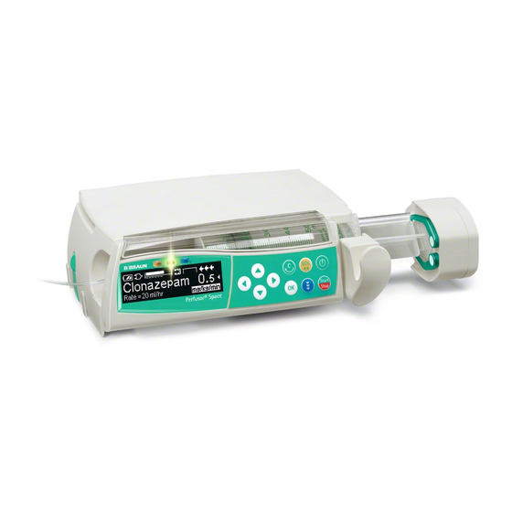
Perfusor® Space
and Accessories
Instructions for Use
It is recommended that all pumps at
your care unit are equipped with the
same software version.
GB
Valid for software 688M
Related Manuals for Braun Perfusor Space

Summary of Contents for Braun Perfusor Space
-
Page 1
Perfusor® Space and Accessories Instructions for Use It is recommended that all pumps at your care unit are equipped with the same software version. Valid for software 688M… -
Page 2: Table Of Contents
CONTENTS Perfusor® Space Overview………………………3 Symbols on Product ……………………….5 Patient Safety ……………………….6 Menu Structure / Navigation……………………11 Chapter 1 Operation ……………………..14 1.1 Start of Infusion …………………….14 1.2 Entry With Different Combinations of Rate, VTBI (= Volume To Be Infused) and Time……………………….15 1.3 Bolus Application ……………………16 1.4 Syringe Change and New Therapy Start …………….17 1.5 End of Infusion……………………..18 1.6 Standby Mode ……………………..18…
-
Page 3: Perfusor® Space Overview
PERFUSOR SPACE® OVERVIEW P E R F U S O R ® S PA C E O V E R V I E W Arrow up and -down Press to reset single values Drive head with Scroll through menus, change setting of numbers from 0-9,…
-
Page 4
For vertical fixation of PoleClamp push lever down and rotate either way until lever clicks into notch. Push lever for rotation. Caution: A maximum of three B. Braun Space pumps can be stacked together when used with the PoleClamp SP. -
Page 5: Symbols On Product
SYMBOLS ON PRODUCT S Y M B O L S O N P R O D U C T Symbol Explanation Mandatory action: see instruction for use. See accompanying documents. Type CF unit with defibrillation protection Protection class II device Symbol indicating separate collection for electrical and electronic equipment (2002/96/EC) CE mark compliant to Directive 93/42/EEC…
-
Page 6: Patient Safety
Operation • The initial training of the Perfusor® Space is to be performed by B. Braun sales personnel or other authorized persons. After each software update, the user is required to inform himself of the changes to the device and accessories by referring to the Instructions for Use.
-
Page 7
PATIENT SAFETY • Only connect to patient once the syringe has been inserted correctly and there is proper fixation of the syringe pressure plate by the claws of the drive head. Interrupt connection during syringe change to prevent incorrect dose delivery. -
Page 8
PATIENT SAFETY Enteral Nutrition The Perfusor® Space may be used for enteral nutrition. Do not use enteral fluids for intravenous infusion as this may harm your patient. For this reason only use disposables dedicated and labeled for enteral nutrition. Other components •… -
Page 9
TCI and properly trained in using the present device. • The use of TCI with B. Braun Space does not limit the responsibility of the anaesthetist for administration of drugs. They need to be fully aware of the available literature for any parameter set used in association with a drug and need to refer to the prescribed information for rate and dosing limits. -
Page 10
PATIENT SAFETY • While using TCI an appropriate patient monitoring is mandatory. • Take care of using the right dilution/concentration of the drug and make sure the right dilution is selected at the pump. • Never administer Propofol or Remifentanil by a second infusion as long as you use TCI. -
Page 11: Menu Structure / Navigation
MENU STRUCTURE / NAVIGATION MENU STRUCTURE / NAVIGATION Cutline On/Off button OK button Start/Stop button Keypad with arrow up, -down, -left, -right button Bolus button Connection button Clear button All display screen shots are examples and may be different when related to an individual patient and individualized therapy.
-
Page 12
MENU STRUCTURE / NAVIGATION Display Meaning All status information is available in the bottom line of the dislplay. The desired information can be selected by using and will be displayed permanently thereafter (e. g. drug long name, time until syringe empty, current system pressure etc.). -
Page 13
MENU STRUCTURE / NAVIGATION Start Up Main Special Options Status Menu Menu Functions Menu Menu Syringe Dose Rate Occlusion Intermediate Dose selection Calculation Pressure volume Intermediate Prime ? Concentration Drug Library OccluGuard amount Change-over Use last Pressure Intermediate Weight therapy ? from Leap/Drop time… -
Page 14: Chapter 1 Operation
OPERATION Chapter 1 OPERATION 1.1 Start of Infusion • Ensure correct installation of the pump device. If the pump is connected to mains, the display states information such as the battery status, the mains connection symbol and the last therapy. •…
-
Page 15: Entry With Different Combinations Of Rate, Vtbi (= Volume To Be Infused) And Time
OPERATION Chapter 1 • Press to commence infusion. Running arrows on display and green LED above display indicate pump is infusing. Note: Stop the infusion at any time by pressing . The pump can be turned off at any time by pressing for 3 sec (Exception: Data lock level 2) and as long a disposable is inserted.
-
Page 16: Bolus Application
OPERATION Chapter 1 a) Target symbol is placed in front of VTBI: • Change of VTBI => Adjustment of time. Old and new target: VTBI • Change of time => Adjustment of rate. Old and new target: VTBI b) Target symbol is placed in front of time: •…
-
Page 17: Syringe Change And New Therapy Start
OPERATION Chapter 1 1.4 Syringe Change and New Therapy Start Note: To avoid incorrect dosing, always disconnect the pump from the patient when changing the syringe. Never leave the pump device unattended during syringe change. Before inserting a new syringe check if the axial fixation is properly working. •…
-
Page 18: Standby Mode
OPERATION Chapter 1 • Open pump cover. Remove the syringe, move the syringe holder into an upright position and close the front door. • Press for 3 sec. to switch the pump off. The drive moves into parking position. Note: The settings will be permanently saved by the switched off device.
-
Page 19: Chapter 2 Advanced Operations
OPERATION Chapter 1 ADVANCED OPERATIONS 2.1 Status Request of Pump when Infusion is Running Press to switch between run display and Main Menu while the device is infusing. Navigate through the menu using to check parameters. In order to check the menu parameters in the Status-/Options Menu, select «Status»…
-
Page 20: Chapter 3 Special Functions
ADVANCED OPERATIONS Chapter 2 SPECIAL FUNCTIONS 3.1 Dosing Units and Dose Rate Calculation (Overview) The following list shows the units used in the pump: Gram family: ng, mcg, mg, g Unit family: mIU, IU, kIU, MIU Equivalents family: mEq Mole family: mmol Kilocalorie family: kcal Millitliter family:…
-
Page 21: Dose Rate Calculation (Operation)
SPECIAL FUNCTIONS Chapter 3 3.2 Dose Rate Calculation (Operation) a Select dose rate calculation with l. a Select the unit of the active ingredient with and confirm it with l. a Enter the concentration by entering the amount of the active ingredient and the volume.
-
Page 22
SPECIAL FUNCTIONS Chapter 3 On the one hand, a drug name including the according therapy data can be taken from the drug library. On the other hand, if a rate, VTBI and/or time were already defined in the Main Menu, the drug name and the adjusted values of the data set will be loaded. -
Page 23
SPECIAL FUNCTIONS Chapter 3 • Select the desired drug with and press l. Before the initial bolus begins, the bolus menu is displayed to allow editing the bolus with q. • Check the parameter and start infusion with Hard Limits: If the set rate/dose/bolus volume and bolus rate exceed the values stored in the drug library (hard limits), the drug will be rejected, a hint will be displayed and the pump will fall back into the drug selection. -
Page 24: Patient Controlled Analgesia (Pca) (Optional)
SPECIAL FUNCTIONS Chapter 3 The Drug Library Upload starts as soon as the pump is in Passive mode. You can cancel the upload by pressing c. Note: Please contact your local sales represantative in case you like to use Remote Drug Library update.
-
Page 25
SPECIAL FUNCTIONS Chapter 3 In this state the patient is allowed to demand boli. Depending on the status of the therapy these are either administered or denied. Changing the syringe is also possible by using the code for level 1 or level 2. Altering the settings for PCA or other therapies however is only possible with the code for level 3. -
Page 26: Target Controlled Infusion (Tci) (Optional)
The pharmacokinetic model and its parameters are schematically depicted by the following illustration: B. Braun Space is offering two modes for TCI: • TCI by targeting the plasma concentration In this mode the user selects the desired concentration of a drug in the…
-
Page 27
TCI. A pharmacokinetic model modi- fied in such way is schematically depicted by the illustration on the next page. TCI with B. Braun Space is possible with two drugs: Propofol and Remifentanil. For Propofol the user can choose between two parameter sets. The parameter… -
Page 28
SPECIAL FUNCTIONS Chapter 3 Drug / Parameter Propofol Remifentanil [Litre] 0,228 * Weight 4,27 5,1 — 0,0201 * (Age — 40) + 0,072 * (LBM — 55) [min 0,119 0,443 + 0,0107 * (Weight — [2,6 — 0,0162 * (Age — 40) + 77) — 0,0159 * (LBM — 59) + 0,0191 * (LBM — 55)] / [5.1 — 0,0062 * (Height — 177) -
Page 29
Chapter 3 Important note: Before installing an additional drug list please contact your local B. Braun representative! Setting up the pump For TCI a drug list with at least one drug activating the profile TCI is necessary. The drug list in this version is pre-defined. By this the conditions for an effective and safe therapy are defined. -
Page 30
SPECIAL FUNCTIONS Chapter 3 Important notes: • Be sure to enter the data corresponding to the respective patient. • Once the TCI is started patient data can not be altered! Editing a target and starting TCI The editor window for setting the target comes up with the default value from the drug list. -
Page 31
SPECIAL FUNCTIONS Chapter 3 Useful information while pump is running By pressing additional information can be requested. Pressing a second time is offering a graphical overview. The line describes the course of Cp over the time and the area describes the course of Ce over the time. -
Page 32: Barcoding
SPECIAL FUNCTIONS Chapter 3 Barcoding The barcoding functionality is included but initially not activated. Please contact your local sales representative in case you like to use barcoding. Ramp and Taper Mode The Ramp and Taper Mode is designed to deliver infusions with gradual ramp up and taper down rates.
-
Page 33
SPECIAL FUNCTIONS Chapter 3 Set Profile Parameters: The therapy can be started directly via the drug library or via the Main Menu/Special functions. Starting Ramp and Taper via Drug Library: Note: Ramp and Taper settings have been configured in the Drug List Manager before and have been uploaded into the pump. -
Page 34: Program Mode
SPECIAL FUNCTIONS Chapter 3 Taper phase The pump linearly decreases the rate in the predefined time until it reaches the KVO rate Note: After starting infusion it is only possible to change rates, time and VTBI in the continuous phase. By editing (increasing/decreasing) the plateau rate, the therapy is recalculated.
-
Page 35
SPECIAL FUNCTIONS Chapter 3 Example: Program Mode should only be performed by an experienced user being familiar with the principles of the Program Mode function and properly trained in using the present device. Note: The active Program Mode function always displays this icon in the Display Note: Bolus function is disabled for Program Mode. -
Page 36: Intermittent Mode
SPECIAL FUNCTIONS Chapter 3 The pump can be started now by pressing Starting Program Mode via Special Function Menu: • Switch on pump with and wait until self-check is finished. • Insert disposable. • Go to Special Functions Menu and select Program Mode. •…
-
Page 37
SPECIAL FUNCTIONS Chapter 3 Example: Intermittent Mode should only be performed by an experienced user being familiar with the principles of the Intermittent Mode and properly trained in using the present device. Note: The active Multi Dose Mode function always displays this icon in the Display Note: Regular Bolus function is disabled for Intermittent Mode. -
Page 38
SPECIAL FUNCTIONS Chapter 3 Starting Intermittent Mode via Special Function Menu: • Switch on pump with and wait until self-check is finished. • Insert disposable. • Go to Special Functions Menu and select Intermittent Mode. • Press to enter parameters and to confirm. -
Page 39: Dose Over Time
Note: The feature Dose Over Time always requires the usage of dosing units (i.e., mg or mg/kg patient weight). Before using Dose Over Time contact your local B. Braun representative! Starting Dose Over Time via Drug Library: Note: Dose Over Time settings have been configured in the Drug List Manager before and have been uploaded into the pump.
-
Page 40
SPECIAL FUNCTIONS Chapter 3 • Insert disposable and use the drug library according to the Instructions for Use. • Select a drug by using and press l. The pump now offers the possible therapy profiles. Select “Dose over Time” with press l. -
Page 41: Take Over Mode (Tom) (Optional)
SPECIAL FUNCTIONS Chapter 3 3.11 Take Over Mode (TOM) Take Over Mode is a feature to support the user during syringe changes by auto- matically starting a second Perfusor® Space pump when the first has run empty. The second pump automatically takes over the infusion rate from the first pump. Activation: •…
-
Page 42
SPECIAL FUNCTIONS Chapter 3 • Navigate through the list with and select in alphabetical order (all drugs) or within a category with l. The drug selected in the second pump must be the same as the first. • Navigate through the list with and select a concentration with l. -
Page 43
SPECIAL FUNCTIONS Chapter 3 Note: Start-up behaviour is not influenced by TOM. See Chapter Start Up Graphs and Trumpet Curves. Note: Please use a seperate patient connection for Take Over Mode infusion (e.g. smallbore extension set) or use a back check valve for lines at the same access which are not used for Take Over Mode. -
Page 44
SPECIAL FUNCTIONS Chapter 3 Recommendation Ensure first Perfusor® Space pump is infusing Ensure first Perfusor® Space pump must be running in ‘continuous mode’ (i.e. ml/h or a dose rate; not KVO, PCA etc.) Deactivate Data Lock Data connection must be active between pumps –… -
Page 45
SPECIAL FUNCTIONS Chapter 3 Changes in TOM system: Change Reaction Rate changed in pump No user interaction necessary, will start infusion at new rate when syringe is empty. pump is stopped pump shows “connection lost – TOM aborted” alarm. TOM may be reactivated by pump is put in standby pressing and then… -
Page 46: Chapter 4 Autoprogramming
AUTOPROGRAMMING Chapter 4 A U TO P R O G R A M M I N G Note: All normal pump functions remain in place when orders are received via autoprogramming. The pump can accept drug orders wirelessly from the EHR system or from SpaceStation with SpaceCom.
-
Page 47
AUTOPROGRAMMING Chapter 4 Note: Order may be cancelled prior to confirming order. • Once all values are confirmed, the Main Menu is displayed. Note: Soft Limit alert will be issued if value exceeds any soft limits set in drug library, soft limit may be overridden or value re-programmed per institutional policy. -
Page 48
AUTOPROGRAMMNG Chapter 4 • Follow prompt, pressing to accept order or key to cancel and hold order for later. New Primary Infusion: • To accept a new PRIMary order, stop infusion and clear current PRIMary infusion by pressing key and responding “yes” to clear current infusion. PIGGYback Orders: Orders received after PRIMary has been set will be for PIGGYback infusions, follow prompts on screen to stop the PRIMary to accept the PIGGYback order. -
Page 49
AUTOPROGRAMMING Chapter 4 Note: Changing values on any incoming order may only be done after confir- ming all values. Once all values are confirmed you may scroll to any value and open editor with to change value. Alternately, order may be cancelled and request made for revised order to be sent. -
Page 50: Chapter 5 Options
OPTIONS Chapter 5 OPTIONS The options functions may be selected and changed while the pump is infusing or stopped. To edit a menu item, select “Options” in the Main Menu and press l. Then select desired function with and follow the Instructions for Use as described. 5.1 Occlusion Pressure The higher the pressure level is set at, the higher the pressure level must rise before triggering an occlusion pressure alarm.
-
Page 51
OPTIONS Chapter 5 OccluGuard activation / deactivation from the Main Menu • Go to Options Menu and press l. • Navigate through the list with and select OccluGuard. • OccluGuard can be activated with and deactivated with d. Pressure Leap/Drop detection The pressure leap/drop software detects sudden increases and decreases in infu- sion pressure respectively which can be caused by problems in IV access, or changes in pump position in the SpaceStation. -
Page 52
OPTIONS Chapter 5 OccluGuard Meaning Recommendation Symbol OccluGuard is active. Infusion is running stably Pending – OccluGuard has not enough data OccluGuard will automatically reactivate as soon as infusion rate OccluGuard Inactive drops below threshold levels – see above. Confirm alarm and check IV access, IV setup and syringe for cause of Occlusion has been occlusion. -
Page 53: Data Lock
OPTIONS Chapter 5 When a change is made to the infusion system (e.g. addition or removal of a pump to a SpaceStation, a change of infusion rate, a bolus application) the OccluGuard and pressure leap/drop are temporarily set to ‘pending’ ( ) to allow the system to reach a hydrostatic balance, and so prevent false alarms.
-
Page 54: Bolus Rate
OPTIONS Chapter 5 Activation of the function: • Open data lock in Options Menu with l. • Select between level 1, 2 or 3 (if activated) with and confirm with k. • Enter code with and press in order to activate data lock. Changes to the protected values and the bolus function which are marked withy are only possible after entering the code.
-
Page 55: Alarm Volume
OPTIONS Chapter 5 5.7 Alarm Volume Chose between 9 different alarm volume levels. • Open alarm volume in Options Menu with l. • Set volume with and confirm entry with k. 5.8 Date / Time • Open date/time in Options Menu with l. •…
-
Page 56: Chapter6 Alarms
ALARMS Chapter 5 ALARMS The Perfusor® Space is equipped with a audible and optical alarm signal. Audible Alarm- Optical signal Staff call User confirmation type signal Red LED Yellow LED Text Device flashes device Press and follow Alarm alarm and the instruction on the alarm code display.
-
Page 57
ALARMS Chapter 6 Display message Pre-alarm reason “Syringe nearly empty“ Very little fluid is left in syringe. “VTBI near end“ The preselected volume is nearly infused. “Time near end“ The preselected time is almost over. “Battery nearly empty“ The battery is almost discharged. “KVO mode“… -
Page 58
ALARMS Chapter 6 the alarm message, and the staff call (optional) are all cleared by pressing k. Corrections should be made in accordance with the alarm reason. Display message Alarm reason “Syringe empty“ There is no fluid left in the syringe. Due to varying syringe tolerances of syringes from other manufacturers, some fluid may be left inside the syringe. -
Page 59
ALARMS Chapter 6 “Calibrate device“ Pump calibration data have changed (e.g. after an update). Recalibrate device via the service program. “Claw malfunction“ The emergency release button was pressed and the claws manually opened. Take out syringe and contact technical service department. “Plunger plate not prop. -
Page 60: Reminder Alarms
ALARMS Chapter 6 6.3 Reminder Alarms Reminder alarms only occur in two cases: 1. A syringe is inserted, the pump doesn’t administrate, no value is being edited and the device is not operated for two minutes. An acoustic tone sounds, the yellow LED is constantly on and a staff call is activated.
-
Page 61: Battery Operation And Maintenance
BATTERY OPERATION AND MAINTENANCE Chapter 7 BATTERY OPERATION AND MAINTENANCE The battery has an operating lifetime of 8 hours at 25 ml/h when new. For optimal treatment of the battery, the device is equipped with protection against overcharge and deep depletion. The battery pack is charged by the pump during connection to mains.
-
Page 62
BATTERY OPERATION AND MAINTENANCE Chapter 7 • If a battery, which is not completely discharged, is charged several times, its capacity can be reduced. • Under normal temperature conditions a battery can be charged and discharged approx. 500 times before its lifetime decreases. •… -
Page 63: Chapter 8 Compatible Syringes
) to ensure specific syringe brand compatibility. The Time to Occlusion alarm has been measured at 5 ml/h. The measured data are typical values which may vary because of possible syringe tolerances. Manufacturer: B. Braun Syringe Type Omnifix Omnifix Omnifix Omnifix Omnifix B.
-
Page 64
COMPATIBLE SYRINGES Chapter 8 Manufacturer: TYCO USA Syringe Type Monoject Monoject Monoject Monoject Monoject Monoject 3 ml 6 ml 12 ml 20 ml 35 ml 50/60 ml TYCO USA Mat. No. 8881- 8881- 8881- 8881- 8881- 8881- 513934 516937 512878 520657 535762 560125… -
Page 65
COMPATIBLE SYRINGES Chapter 8 Manufacturer: TERUMO Syringe Type 3 ml 5 ml 10 ml 20 ml 30 ml 50 ml 60 ml TERUMO EU/USA/JAP Mat. No. 3SS*03L 3SS*05L 3SS*10L 3SS*20L 1SS*30LZ1 2BS-50LG 3SS*60L 1SS*05LZ1 1SS*10LZ1 SS*20ES typ. typ. typ. typ. typ. -
Page 66
COMPATIBLE SYRINGES Chapter 8 Manufacturer: Becton-Dickinson Syringe Type BD Precise BD Precise B-D Precise 50 ml A/P 20 ml A/P Mat. No. 300144 300141 Time to Occl. [mm:ss] 03:17 01:11 [mm:ss] 16:36 05:03 Manufacturer: Polfa Syringe Type Polfa 50 ml Mat. -
Page 67
COMPATIBLE SYRINGES Chapter 8 Syringes not specified in IEC/EN 60601-2-24 Nutrition pumps, in contrast to infusion pumps, are not classified as Class IIa according to the infusion pump norm IEC/EN 60601-2-24. There are therefore no direct guide- lines concerning the technical characteristics (accuracy of infusion rate, alarm parameters etc) of the relevant disposables. -
Page 68: Start Up Graphs And Trumpet Curves
START UP GRAPHS AND TRUMPET CURVES Chapter 9 START UP GRAPHS AND TRUMPET CURVES Start Up Curves Trumpet Curves The graphs show the accuracy/uniformity of flow in relation to time. They allow for the following: The delivery behaviour or delivery precision is essentially influenced by the type of (disposable syringe) used.
-
Page 69: Is Depending On Chapter10 Technical Data
Moisture protection IP 22 (fluid protected for horizontal usage) External power supply: • Rated voltage Via B. Braun SpaceStation or optional mains adaptor (rated voltage 100 … 240 V AC~, 50/60 Hz) for stand alone operation • External low voltage 11 ……
-
Page 70
Delivery rate 1 ml/h: KVO-rate = set rate (default setting 0.1 ml/h) Computer connection USB connection in combination with B. Braun interface lead CAN SP (8713230) including electrical insulation. Please pay attention to safety notices. History protocol < 3000 last history entries. -
Page 71
TECHNICAL DATA Chapter 10 • Only use combined with approved devices/accessories by the manufacturer, otherwise this may lead to higher emission or reduced immunity. • Use only compatible combinations of equipment, accessories, working parts and disposables with luer lock connectors. Essential Performance for Infusion pumps: •… -
Page 72
TECHNICAL DATA Chapter 10 EMC (ELECTROMAGNETIC COMPATIBILITY) -
Page 73
TECHNICAL DATA Chapter 10… -
Page 74
TECHNICAL DATA Chapter 10… -
Page 75
TECHNICAL DATA Chapter 10… -
Page 76: Warranty / Tsc* / Service / Training / Cleaning / Disposal
• the Technical Safety Checks are carried out regularly. Warranty The CE mark confirms that this B. Braun provides 24 months warranty, as from the date of delivery, for every medical product Perfusor® Space (12 months for every Battery-Pack SP). This covers repair or complies with the replacement of parts damaged as a result of design/manufacturing errors or «Council Directive…
-
Page 77
Note: Do not use Hexaquart® or other alkylamine containing disinfectants. Recommended: disinfectant for wiping available from B. Braun: Meliseptol® Foam pure, Melsitt 10% and Melsept SF 10%. Note: Keep instrument upright and do not allow any part of instrument to become saturated with or submersed in fluid during cleaning operation. -
Page 78
Disposal The pumps as well as battery packs can be returned to B. Braun for further disposal. When taking care of disposing of disposables as well as infusion soluti- ons, please consider the applicable hygiene and disposal regulations. -
Page 79: Instructions For Use Accessory
Comfort additionaly includes a central alarm management and alarm LEDs. PoleClamp SP (8713130) A maximum of three B. Braun Space pumps and one SpaceControl can be stacked together when used with the PoleClamp SP. For detailed instructions on secure fixation of the PoleClamp SP please refer to «Overview Perfusor® Space»…
-
Page 80
INSTRUCTIONS FOR USE ACCESSORY Chapter 12 3.) Push plug of Connection Lead SP into 12 V connector. Note: A maximum of three plugs can be stacked upon each other in socket P2. Battery-Pack SP (NiMH) (8713180) Battery-Pack SP (NiMH) incl. Pin (8713180A) For further information on the Battery-Pack SP (NiMH) see “Battery Operation”. -
Page 81
INSTRUCTIONS FOR USE ACCESSORY Chapter 12 Connection Lead SP (12 V) (8713231) Install the Connection Lead SP (12 V) in the following way: 1.) Connect plug to socket P2 on back of pump or F3 on SpaceStation respectively. 2.) Put the connection lead into the car socket. 3.) If necessary, remove red adaptor of motor vehicle connector by slightly turning and simultanously pulling. -
Page 82
INSTRUCTIONS FOR USE ACCESSORY Chapter 12 Caution: The user should always closely observe the local pump alarms as well. Note: A maximum of three plugs can be stacked upon each other in socket P2. Technical Data Connecting Wire white and green white and brown Alarm disconnected… -
Page 83
INSTRUCTIONS FOR USE ACCESSORY Chapter 12 P C A — A c c e s s o r i e s • Space PCA-Kit (REF 8713554) consisting of: : — Demand button — Hook and loop tape for fixation of the demand button at the patient s arm — Line fixation connection between hook and loop tape… -
Page 84: Ordering
ORDERING Art. No. B. Braun Perfusor® Space (100 – 240 V) ……….871 3030 Recommended accessories for the B. Braun Perfusor® Space: SpaceStation ………………..871 3140 SpaceCover Standard ………………871 3147 SpaceCover Comfort ………………871 3145 PoleClamp SP…………………871 3130 Power Supply SP EU III ……………….871 3110D Power Supply SP EU III 3.0m……………..871 3123D…
-
Page 85
ORDERING 50ml, yellow inked cylinder and aspiration needle…….87 28801 F 50ml, yellow inked cylinder, aspiration needle and 15 µm particle filter …………….872 8800 F 50ml, black, aspiration needle and particle filter……..872 8828 F Omnifix® syringes Omnifix® 50/60 ml Luer Lock……………461 7509F Omnifix®… -
Page 86
ORDERING Type PCA, PVC tube 1,5 mm, 150 cm, Luer Lock ……..872 6019 with 0.2 µm Sterifix filter, PVC tube 1,5 mm, 200cm, Luer Lock …………………872 3001 with SafeSite valve, PVC tube 1,5 mm, 150 cm, Luer Lock………………..872 2820… -
Page 90
Manufactured by: B. Braun Melsungen AG B. Braun Melsungen AG Sparte Hospital Care 34209 Melsungen 34209 Melsungen Germany Germany Tel +49 (0) 56 61 71-0 Tel.: +49 (0) 56 61 71-0 Fax: +49 (0) 56 61 71-20 44 38916517 • Drawing No. I0688700201 Printed on pulp bleached 100 % chlorine-free www.bbraun.com…
- Manuals
- Brands
- B. Braun Manuals
- Medical Equipment
- Perfusor Space
- Service manual
-
Contents
-
Table of Contents
-
Troubleshooting
-
Bookmarks
Quick Links
1.0
1.3
Perfusor® Space
Service Manual
Version 1.3 English
Related Manuals for B. Braun Perfusor Space
Summary of Contents for B. Braun Perfusor Space
-
Page 1
Perfusor® Space Service Manual Version 1.3 English… -
Page 2
This Service Manual is valid for: Designation Part No. Infusion syringe pump Perfusor® Space … . 0871 3030 This Service Manual is available under Designation Part No. the following part number: Service Manual Perfusor®… -
Page 3
Table of Contents Important Preliminary Remarks Service Work Page 0 — 5 Technical Safety Checks Page 0 — 5 Current Versions Page 0 — 5 Revision Service Page 0 — 5 Quality Management Page 0 — 6 Checks and Repair Page 0 — 6 Notes on ESD… -
Page 4
Table of Contents Servicing the Unit Cleaning Page 4 — 1 Servicing the Battery Page 4 — 1 Technical Safety Check (TSC) Perfusor® Space 1 Technical Safety Check (TSC) Power Supply SP 1 Procedural Instructions on the TSC Visual Inspection Page 7 — 1 Electrical Safety… -
Page 5
You will be included in the revision service after: technical training by B. Braun Melsungen or a written order placed with the sales department of B. Braun (fee required). Perfusor® Space, 1.1 gb 0 — 5… -
Page 6
B. Braun unit. Quality Management B. Braun is certified in accordance with DIN EN ISO 9001 and ISO 13485. This certification also includes maintenance and service. The unit has the CE label. The CE label confirms that the device corresponds to the “Directive of the Council for Medical Products… -
Page 7
Service personnel are responsible for the calibration of their test equipment. Original test equipment can be calibrated at the works of B. Braun. Further information is available upon request. Setting Off Additional notes and warnings are set off as follows:… -
Page 8
Important Preliminary Remarks References to chapters are shown as follows (see “Setting Off“ pg. 0 — 7) References to figures and tables are shown as follows Fig.: 2 — 3 Table 2 — 1 References to item numbers in figures are shown as follows (Fig.: 1 — 1 / Item In this case “Fig.: 1 — 1“… -
Page 9
Important Preliminary Remarks List of Abbreviations Abbreviations which are not generally known, but are used in this manual, are listed below. Controller Area Network Communauté Européenne (European Communities) Calibration Step Deutsche Industrie Norm (German Industrial Standard) European Standard Electrostatic Discharge Function Microprocessor International Electrotechnical Commission… -
Page 10
Important Preliminary Remarks Unit Test Step Verband der Elektrotechnik, Elektronik und Informationstechnik e.V. (German electrical engineering association) 0 — 10 Perfusor® Space, 1.2 gb… -
Page 11
Entry for Technical Training Application for a technical training course must be made via the responsible representative. Ordering of Spare Parts and Test Equipment Please contact your local B. Braun subsidary. International Technicians (Intercompany) Nadja Machal Fax: +49 5661 / 75 — 47 89 e-mail: nadja.machal@bbraun.com… -
Page 12
Contact Persons For your notes: 0 — 12 Perfusor® Space, 1.0 gb… -
Page 13
System Overview Description The Perfusor® Space (PSP) is according to IEC/EN 60601 resp. IEC/ EN 60601-2-24 a transportable infusion syringe pump for administrating fluids in the nutritional therapy and infusion technique as well as for home care applications. The medical specialist must decide on suitability for application on the basis of the warranted properties and the technical data. -
Page 14
System Overview Physical Construction Fig.: 1 — 2 Perfusor® Space Legend of fig. 1 — 2: ItemDesignation Perfusor® Space Connector “P2“ for SpaceStation module, external 12 V DC and accessories Drive head Connector “P3“, connection to SpaceControl module Syringe holder with piston brake Battery compartment cover Operating Unit Syringe area… -
Page 15
System Overview The Perfusor® Space housing mainly consists of the bottom part and the upper part. The battery module is inserted in the rear of the housing upper part. The opening is covered by the battery compartment cover. The operating unit is attached to the front of the bottom part with two hinges. -
Page 16
System Overview The pressure in the infusion system is measured through a strain gauge measuring in the drive head and monitored in the device electronics. The data from the strain gauge is continuously compared with the limit values which are calculated dependent on the selected syringe type and the pressure settings. -
Page 17
System Overview Fig.: 1 — 3 Block diagram Perfusor® Space Perfusor® Space, 1.0 gb 1 — 5… -
Page 18
System Overview Unit Software Approved Software Versions 688A030032 Basic software Position 1 2 3 4 5 6 7 8 9 10 688A030035 Digit 6 8 8 C 0 3 0 0 0 1 Improved functions 688A030040 Revision level Improved functions Hardware Languages French and Swedish added Software group… -
Page 19
PC is switched off, a component of the software may be seriously damaged so that repairs are no longer possible. In such a case the software cannot be updated via the PC and the device must be returned to B. Braun. Service Program Approved Version… -
Page 20
System Overview 1. Start the “HiBaSeD.exe” program (History, Barcode, Service, Drug list) on the PC. The Service Program is loaded and started and the initial window of the Service Program is displayed. 2. Read the notes carefully. 3. Mark the field “I accept all conditions” and then the field “Yes”… -
Page 21
System Overview The work window of the Service Program appears on the screen. All devices recognized are listed in the left column. Fig.: 1 — 8 5. Activate the desired device from the list on the left in the work window with a double-click. The device data is then displayed below the device name. -
Page 22
System Overview If the unit software version is not compatible with the Service Program version, a window opens prompting the operator to change the Service Program version. This window displays a compatibility list of the Service Program- and unit software versions. -
Page 23
System Overview Service Program Version Help Info … 1. Open the “HiBaSeD“ window via . The current version of the Service Program is shown in this window. 2. Close the window by clicking “OK”. Fig.: 1 — 11 Compatibility List Help 1. -
Page 24
System Overview Technical Data All technical data is indicated in the instructions for use. Options The functions of the individual options are detailed in the instructions for use. Perfusor® Space Designation Part No.: Power supply Euro ……0871 3110A Power supply UK. -
Page 25
Unit Diagnosis / Calibration General WARNING WHILE TESTING THE UNIT AND TROUBLE SHOOTING THE OPERATOR/SERVICE TECHNICIAN MUST WORK WITH VOLTAGES UP TO 115 / 230 V AC. THESE VOLTAGES MAY CAUSE INJURIES WHICH ARE DANGEROUS TO LIFE AND LIMB. THE NATIONAL AND INTERNATIONAL SAFETY REGULATIONS ARE TO BE ADHERED TO. -
Page 26
Unit Diagnosis / Calibration The unit check, calibration and trouble shooting are subdivided into numbered working steps (Unit Test Step UTS, Calibration Step CS, Trouble Shooting TS) and are based on each other. Beginning with UTS 1 the operation described here has to be executed. -
Page 27
Unit Diagnosis / Calibration Alarms and Error Codes The alarms of the Perfusor® Space are classified in 5 categories. These categories are listed hereafter according to their importance. Alarm advice In case of unacceptable inputs corresponding messages are displayed (e.g. “Caution! Rate out of range“, “The parameter cannot be changed“) and a beep sounds. -
Page 28
Unit Diagnosis / Calibration Alarms Alarm Possible Cause Fault Clearance Battery nearly discharged (type: pre- The device was not connected to the Operate the device with battery until the alarm) mains long enough message “Battery discharged“ is displayed and the unit is switched off. Then connect the unit to the mains for at least 6 hours. -
Page 29
Unit Diagnosis / Calibration Device Alarms of the Function Processor Error Code Definition Possible Cause Fault Clearance 1001 … 1013 Internal Error 1014 Loudspeaker not off Loudspeaker connector Check the loudspeaker connector Loudspeaker Check the loudspeaker 1015 Loudspeaker lost Loudspeaker connector Check the loudspeaker connector Loudspeaker Check the loudspeaker… -
Page 30
Unit Diagnosis / Calibration Device Alarms of the Control Microprocessor Error Code Definition Possible Cause Fault Clearance 1100 Timebase too fast Quartz of the processor PCB Exchange processor PCB 1101 Timebase too slow Quartz of the processor PCB Exchange processor PCB 1102 Timebase fail Quartz of the processor PCB… -
Page 31
Unit Diagnosis / Calibration Error Code Definition Possible Cause Fault Clearance 1201 different version FuP to KuP Software Update unit software Software 1202 E_ERROR_STEPMOTOR_1 Phase Drive motor, lead screw Exchange processor PCB not ok 1203 E_ERROR_STEPMOTOR_2 Current Motor drive Carry out calibration value not 0x55 Recognition of direction of rotation… -
Page 32
Unit Diagnosis / Calibration The Most Important Error Modes The following list specifies the most important error modes and their clearance. Note The device must be checked after every repair or service (see “Device Check“ pg. 2 — Error Possible Cause Fault Clearance The battery module discharges too fast The device was not used for a longer time. -
Page 33
Unit Diagnosis / Calibration Device Check Activity Function If yes If no The device is inserted in a SpaceStation or UTS 2 UTS 3 connected to a SpaceControl. Remove the device. UTS 4 Loosen all connections from the device. UTS 4 Remove syringe and close syringe holder. -
Page 34
Unit Diagnosis / Calibration Activity Function If yes If no Insert 2 ml / 3 ml syringe. On the LC display “Brake: stopped by holder” UTS 22 TS 21 appears in the line. Open syringe holder and remove syringe. On the LC display “Brake: stopped by light barrier” UTS 23 TS 21 appears in the line. -
Page 35
Unit Diagnosis / Calibration Activity Function If yes If no Insert syringe gauge for the strain gauge UTS 41 measurement, close syringe holder and select syringe type „#Lehre OPS50“. The syringe gauge must not be tipped. Therefore fix the syringe gauge so far into the syringe recess by hand that the piston brake moves back and the claws surrounds the pressure element. -
Page 36
Unit Diagnosis / Calibration Activity Function If yes If no Confirm syringe change, release syringe gauge and UTS 48 remove gauge. WARNING WHILE CHECKING THE MOTOR POWER LIMITATION WITH THE SYRINGE GAUGE THE SYRINGE HOLDER MUST NOT BE OPENED. THE SYRINGE GAUGE IS UNDER VERY HIGH PRESSURE AND MAY CAUSE INJURIES IF THE PRESSURE IS RELIEVED SUDDENLY. -
Page 37
Unit Diagnosis / Calibration Activity Function If yes If no Select pressure stage 6 and start infusion. When the maximum pressure of this pressure stage UTS 56 CS 1 is reached, the delivery is stopped, the red LED on the operating unit flashes and the message “Alarm / Drive blocked”… -
Page 38
Unit Diagnosis / Calibration Calibration Activity Function If yes If no Connect unit to PC with interface cable. CS 2 Start Service Program on the PC (see “Starting the The desired device is found by the Service Program CS 3 Service Program“… -
Page 39
Unit Diagnosis / Calibration 1. Start the Service Program (see “Starting the Service Program“ pg. 1 — 2. Select the unit to be calibrated in the left column of the window with a double mouse-click. The blue and the yellow LED blinks in opposite with the red LED. -
Page 40
Unit Diagnosis / Calibration 5. Input your user number in the window “Worker ID” as well as the six-digit serial number of the device, if necessary. 6. Confirm the input with “OK”. Fig.: 2 — 3 Note If HiBaSeD could not clearly read the device serial number, the number must be entered according to the rating plate. -
Page 41
Unit Diagnosis / Calibration Fig.: 2 — 6 Perfusor® Space, 1.2 gb 2 — 17… -
Page 42
Unit Diagnosis / Calibration 8. The frame “Data selection” is now activated. Fig.: 2 — 7 If the “Modify” button was pressed in the “Calibration procedure” frame, the desired data for editing and transmission can now be selected in the “Data selection” frame. -
Page 43
Unit Diagnosis / Calibration 9. Mark at least the “Calibration data“ field in this frame if you have not selected “New device” and confirm by clicking “OK”. The device switches on and the drive head moves to the extended end position. You are prompted to press the blue connection key on the device. -
Page 44
Unit Diagnosis / Calibration Fig.: 2 — 9 11. In the frame “Type of calibration” you can choose between a complete or a partial calibration. Select the desired calibration mode with the mouse pointer. Note The following description is applicable to a complete and a partial calibration. -
Page 45
Unit Diagnosis / Calibration 12. Press the “OK“ button after you have selected the calibration elements. The necessary device data is read out and stored in the PC. Fig.: 2 — 10 Fig.: 2 — 11 Fig.: 2 — 12 Fig.: 2 — 13 Perfusor®… -
Page 46
Unit Diagnosis / Calibration Fig.: 2 — 14 13. The frame “Element selection” is now activated. If you have selected a complete calibration in the “Type of calibration” frame, the individual calibration elements are already selected and cannot be changed. Actuate the “OK” button. -
Page 47
Unit Diagnosis / Calibration Claw Calibration 1. The frame “Claw calibration” is activated and calibration is started. 2. The claws in the drive head are closed and the query “Claw closed? Please confirm” is displayed in the frame “Claw calibration”. 3. -
Page 48
Unit Diagnosis / Calibration 4. Insert diameter gauge 23.4 mm and close the syringe holder. 5. Press the “OK” button. Fig.: 2 — 18 6. Insert diameter gauge 15.7 mm and close the syringe holder. 7. Press the “OK” button. Fig.: 2 — 19 2 — 24 Perfusor®… -
Page 49
Unit Diagnosis / Calibration 8. Insert diameter gauge 9.0 mm and close the syringe holder. 9. Press the “OK” button. Fig.: 2 — 20 10. Open the syringe holder and remove the diameter gauge. Press the “OK” button. Note The syringe holder must always be completely turned and the axial fastening completely opened. -
Page 50
Unit Diagnosis / Calibration 11. Close the syringe holder and actuate the “OK” button. If calibration was not terminated successfully, an error message is displayed on the PC screen. Fig.: 2 — 22 Pressure Calibration Note The term “Power gauge” in the windows of the Service Program corresponds to the syringe gauge. -
Page 51
Unit Diagnosis / Calibration 4. If “Insert power gauge and confirm with OK” is displayed in the frame “Pressure calibration/length/PWM”, open the syringe holder and remove the length gauge. WARNING DURING PRESSURE CALIBRATION WITH THE SYRINGE GAUGE THE SYRINGE HOLDER MUST NOT BE OPENED. THE SYRINGE GAUGE IS UNDER VERY HIGH PRESSURE AND MAY CAUSE INJURIES IF THE PRESSURE IS RELIEVED SUDDENLY. -
Page 52
Unit Diagnosis / Calibration This report can be printed out by pressing the “Print” button. Fig.: 2 — 27 2. Actuate the “OK” button to finish the calibration process and to store the data in the device. 2 — 28 Perfusor®… -
Page 53
Unit Diagnosis / Calibration Trouble Shooting Note The following trouble shooting cannot be carried out independently. It is based on the precise observance of the steps for the device check (see “Device Check“ pg. 2 — 9). From there reference is made to the corresponding trouble shooting steps. Activity Function If yes… -
Page 54
Unit Diagnosis / Calibration Activity Function If yes If no Switch on unit and insert syringe. The syringe piston is fastened with the syringe UTS 19 TS 23 holder blade and the default message is displayed on the LC display. Exchange processor PCB. -
Page 55
Disassembly / Assembly Perfusor® Space 3.1 General Remarks on Disassembly / Assembly Before disassembling the unit, the system must be checked (see “Device Check“ pg. 2 — 9) to isolate the part to be exchanged. The necessary steps to disassemble the complete unit, all its subsystems and spare parts are detailed in the following description. -
Page 56
Disassembly / Assembly Preparations for Exchanging the Processor PCB If the processor PCB is to be replaced a back-up of the pump settings is to be carried out, if this is still possible. 1. Start the Service Program (see “Starting the Service Program“ pg. -
Page 57
Disassembly / Assembly 4. Select the tab “IO”. 5. Press the “To file” button. In the window which opens now you are asked for the storage position of the file on the PC hard disk and the file name. Fig.: 3 — 2 6. -
Page 58
Disassembly / Assembly 7. Actuate the “Display” button to display the device data on screen. With “Close” the window is closed again. Fig.: 3 — 3 8. Select the storage position in the “Save as” window and input a unique file name. 9. -
Page 59
Disassembly / Assembly 10. Select the tab “Disposable articles”. Fig.: 3 — 5 11. Actuate the “From device” button. The data is read from the pump. The data of the disposable articles read out is displayed on screen. Perfusor® Space, 1.2 gb 3 — 5… -
Page 60
Disassembly / Assembly Fig.: 3 — 6 12. Press the “Save as” button. In the window which opens now you are asked for the storage position of the file on the PC hard disk and the file name. 3 — 6 Perfusor®… -
Page 61
Disassembly / Assembly 13. Select the storage position in the “Save as” window and input a unique file name. 14. Press the “Save” button. The data of the pump is saved on the PC hard disk. 15. Exit the Service Program (see “Quit the Service Program“… -
Page 62
Disassembly / Assembly Service Parts and Screw Kit All small parts, such as cover caps, are contained in a Perfusor® Space service part kit. Designation Ord. No. Service part kit Perfusor® Space ….3477 4270 with: housing cover cap (40 pieces) cover caps for operating unit (10 pieces) -
Page 63
Disassembly / Assembly 3.2 Battery Module Designation Ord. No. Battery compartment cover PSP , cpl….3452 0872 Battery pack SP (NIMH)……0871 3180 Disassembly Note Move the drive head to the extended end position before starting… -
Page 64
Disassembly / Assembly 2. Lift the lock (Fig.: 3 — 9 / Item 3) on the battery pack (Fig.: 3 — 9 / Item 1) and remove the battery pack out of the device. Fig.: 3 — 9 Legend of fig. 3 — 9: ItemDesignation Battery pack Battery compartment cover… -
Page 65
Disassembly / Assembly 3.3 Unit Foot Designation Ord. No. Unit foot (see “Service Parts and Screw Kit“ pg. 3 — Disassembly 1. Pull the unit foot (Fig.: 3 — 10 / Item 1) out of the housing. Fig.: 3 — 10 Legend of fig.
 -
Page 66
Disassembly / Assembly 3.4 Operating Unit Designation Ord. No. Operating unit PSP, cpl……3452 0970 Hinge plate PSP, left ……3452 1011 Hinge plate PSP, right . -
Page 67
Disassembly / Assembly 4. Push the right and left connector locks (Fig.: 3 — 12 / Item carefully forward. 5. Disconnect the operating unit connection cable (Fig.: 3 — 12 / Item 1) from the connector. Fig.: 3 — 12 Legend of fig. -
Page 68
Disassembly / Assembly 6. Pull the operating unit from the left hinge plate (Fig.: 3 — 13 / Item 7. Pierce two cover caps (Fig.: 3 — 13 / Item 1) with a small screwdriver and remove cover caps. 8. Unscrew two screws and remove the left hinge plate. Fig.: 3 — 13 Legend of fig. -
Page 69
Disassembly / Assembly Disassembly 1. Pierce six cover caps (Fig.: 3 — 14 / Item 1) with a small screwdriver and remove cover caps. 2. Unscrew six screws and remove the rear panel (Fig.: 3 — 14 / Item Note The three screws of the keyboard must not be loosened. -
Page 70
Disassembly / Assembly 3. Push the right and left connector locks of the PCB keyboard carefully to the left. 4. Pull the LC display ribbon cable (Fig.: 3 — 16 / Item 1) out of the connector. Fig.: 3 — 15 Legend of fig. -
Page 71
Disassembly / Assembly 3.5 Upper Part of Housing Designation Ord. No. Upper part of housing PSP ….. . 3452 0910 Screws and cover caps (see “Service Parts and Screw Kit“… -
Page 72
Disassembly / Assembly 4. Unscrew two screws and remove the contact strip (Fig.: 3 — 18 / Item (Fig.: 3 — 18 / Item Note If necessary, the spring-mounted contact pins must be carefully inserted when the contact strip is dismounted. Fig.: 3 — 18 Legend of fig. -
Page 73
Disassembly / Assembly 3.6 Release Button Designation Ord. No. Release button PSP with leaf spring (see “Service Parts and Screw Kit“ pg. 3 — Disassembly 1. Pull the release button (Fig.: 3 — 19 / Item 1) out of the housing bottom part. -
Page 74
Disassembly / Assembly 3.8 Drive Designation Ord. No. Drive PSP, cpl. Silver claws ……. 3452 1046 Green claws (as from unit software “F”) . -
Page 75
Disassembly / Assembly Fig.: 3 — 23 Legend of fig. 3 — 23: ItemDesignation Screw EJOT 22×8 WN 5451 TORX 6IP A2 Washer Fastening angle Carrier Screw EJOT 22×8 WN 5451 TORX 6IP A2 Drive head Perfusor® Space, 1.1 gb 3 — 21… -
Page 76
Disassembly / Assembly 6. Pull the drive motor connector (Fig.: 3 — 24 / Item 2) off the processor PCB. 7. Unscrew one screw (first temporary screw) and remove the processor PCB ground cable (Fig.: 3 — 24 / Item Fig.: 3 — 24 Legend of fig. -
Page 77
Disassembly / Assembly 8. Unscrew one screw (second temporary screw) and take the drive assembly (Fig.: 3 — 25 / Item 1) out of the housing. Note Please pay attention to the corresponding notes during assembly and installation (see “Assembly / Installation“ pg. -
Page 78
Disassembly / Assembly Disassembly of the Drive Head 1. Pierce two cover caps (Fig.: 3 — 27 / Item 4) with a small screwdriver and remove cover caps. 2. Unscrew two screws (Fig.: 3 — 27 / Item 3. Remove claws (Fig.: 3 — 27 / Item 2) carefully out of the drive head. -
Page 79
Disassembly / Assembly 7. Pull the claw mechanism (Fig.: 3 — 29 / Item 3) off the drive head cover (Fig.: 3 — 29 / Item 2) until the connection cable connector (Fig.: 3 — 30 / Item (Fig.: 3 — 29 / Item 1) can be easily accessed. -
Page 80
Disassembly / Assembly 10. Unscrew one screw (Fig.: 3 — 31 / Item 2) and remove the ground wire (Fig.: 3 — 31 / Item 1) of the drive PCB (Fig.: 3 — 31 / Item 3) from the driving tube. CAUTION Pay attention to the strain gauge (Fig.: 3 — 31 / Item… -
Page 81
Disassembly / Assembly 3.9 Syringe Holder with Piston Brake Designation Ord. No. Piston brake PSP ribbon cable….3452 0864 Syringe holder with piston brake PSP, cpl… 3452 0945 Syringe holder PSP spring . -
Page 82
Disassembly / Assembly 3. Unscrew one screw and remove the locking clip (Fig.: 3 — 33 / Item 2) from the piston brake PCB. Fig.: 3 — 33 Legend of fig. 3 — 33: ItemDesignation Screw EJOT 20×14 WN 5452 TORX 6IP Locking clip 3 — 28 Perfusor®… -
Page 83
Disassembly / Assembly 4. Open the right and left connector lock (Fig.: 3 — 34 / Item on the piston brake PCB carefully. Fig.: 3 — 34 Legend of fig. 3 — 34: ItemDesignation Piston brake connector lock 5. Pull the ribbon cable (Fig.: 3 — 35 / Item 1) out of the connector and remove the cable from the housing. -
Page 84
Disassembly / Assembly 6. Remove the syringe holder spring (Fig.: 3 — 36 / Item 1) from the post in the bottom part of the housing. Note The syringe holder spring can only be removed together with the piston brake drive. Fig.: 3 — 36 Legend of fig. -
Page 85
Disassembly / Assembly 11. Drive the piston brake motor with maximum 3 V DC. The blade is moved out of the syringe holder housing. Note If the blade moves into the syringe holder housing, then the polarity on the piston brake motor must be changed. 12. -
Page 86
Disassembly / Assembly 14. Unscrew one screw and remove the bearing cover (Fig.: 3 — 40 / Item 15. Take the lock (Fig.: 3 — 40 / Item 3) out of the bearing housing. Fig.: 3 — 40 Legend of fig. 3 — 40: ItemDesignation Screw EJOT 20×12 WN 5452 TORX 6IP Bearing cover… -
Page 87
Disassembly / Assembly 18. Unscrew two screws and remove guide rail (Fig.: 3 — 42 / Item 2) out of the bottom part of the housing. 19. Take piston brake motor assembly (Fig.: 3 — 42 / Item 4) out of the housing bottom part. -
Page 88
Disassembly / Assembly 3.10 Processor PCB Designation Ord. No. Processor PCB PSP ……3452 0880 (incl. -
Page 89
Disassembly / Assembly 3.11 Assembly / Installation Assembly or installation of the modules and subsystems is done in reverse order of disassembly. Special steps to be observed are described hereafter in detail. Only new cover caps are to be used. Special Screws Special screws for plastic housings are used in this unit. -
Page 90
Disassembly / Assembly Processor PCB When the processor PCB is replaced all data of the pump except for the calibration data was probably saved on a PC (see “Preparations for Exchanging the Processor PCB“ pg. 3 — Carry out the following steps to transmit the data back to the device. -
Page 91
Disassembly / Assembly Fig.: 3 — 44 4. Select the desired file with the mouse pointer and press the “Open” button. Fig.: 3 — 45 Perfusor® Space, 1.2 gb 3 — 37… -
Page 92
Disassembly / Assembly 5. Change to the tab “IO” and actuate the “To device” button. Fig.: 3 — 46 6. Press the “OK” button when the window “Confirmation” is displayed. Fig.: 3 — 47 3 — 38 Perfusor® Space, 1.2 gb… -
Page 93
Disassembly / Assembly 7. Enter your worker id in the window “Worker ID”. Press the “OK” button to transmit the data to the device. Fig.: 3 — 48 A message is displayed that a change of the device data may affect the patients. -
Page 94
Disassembly / Assembly 8. Select the tab “Disposable articles”. Fig.: 3 — 50 9. Press the “Load from“ button. The window “Open” is displayed on screen. 3 — 40 Perfusor® Space, 1.2 gb… -
Page 95
Disassembly / Assembly 10. Select the desired file with the mouse pointer and press the “Open” button. The data loaded is displayed on screen. 11. Actuate the “To device” button. Fig.: 3 — 51 Fig.: 3 — 52 Perfusor® Space, 1.2 gb 3 — 41… -
Page 96
Disassembly / Assembly 12. Press the “OK” button when the window “Confirmation” is displayed. Fig.: 3 — 53 13. Enter your worker id in the window “Worker ID”. Press the “OK” button to transmit the data to the device. Fig.: 3 — 54 A message is displayed that a change of the device data may affect the patients. -
Page 97
Disassembly / Assembly Loudspeaker 1. Route the loudspeaker connection cable between the drive motor and its connection wires, see Fig.: 3 — Fig.: 3 — 56 Piston Brake WARNING PAY ATTENTION TO THE PISTON BRAKE BLADE WHEN WORKING ON THE PISTON BRAKE. THE BLADE IS SHARP AND MAY CAUSE INJURIES. -
Page 98
Disassembly / Assembly Drive Head 1. Insert the drive head PCB with the strain gauge vertically in the drive head cover. Please note that the strain gauge must not get jammed in the guide. Note The three strain gauge tongues are level with the PCB upper side. 2. -
Page 99
Disassembly / Assembly Note Check the position of the emergency release tappet before mounting the drive head housing. Fig.: 3 — 60 5. Push the drive head housing on to the driving tube until the switch flag of the membrane tappet is positioned just before the claw mechanism. -
Page 100
Disassembly / Assembly Note Pay attention to the syringe wing sensor when inserting the side part of the housing and make sure that the sensor can be operated correctly. 1. Route the ribbon cable through the slide nut before pushing in the driving tube and then through the slide in front of the spindle nut when looking from the rear of the housing. -
Page 101
Disassembly / Assembly Operating Unit Note Before fitting the rear panel check the screw lengths. The screws may only be 4.5 mm long (without head). Longer screws must be exchanged. Note Before mounting the operating unit check the plastic foam gaskets in the housing opening for the connection cable to the operating unit. -
Page 102
Disassembly / Assembly Check List for Checks after Repair Visual Inspection Electrical Safety Functional Inspection according to IEC/EN 60601-1 or VDE 0750 and VDE 0751 Cleanliness The patient and housing leakage current of Locking with second unit Completeness the Perfusor® Space is caused exclusively by Operating unit magnets the operating voltage supply (Power Supply Battery compartment cover… -
Page 103
Disassembly / Assembly Visual Inspection Electrical Safety Functional Inspection according to IEC/EN 60601-1 or VDE 0750 and VDE 0751 Pressure cut off according to TSC Syringe type: «#Lehre OPS50“ Delivery rate: 200 ml/h WARNING REMOVE SYRINGE GAUGE ONLY WHEN RELEASED. DANGER OF INJURY! Strain gauge pressure measurement Pressure stage 1 _______ N… -
Page 104
Disassembly / Assembly For your notes: 3 — 50 Perfusor® Space, 1.0 gb… -
Page 105
For disinfection by wiping, you should use for example Meliseptol® from B. Braun. Allow the unit to dry for at least one minute. When you disinfect the device by spraying, make sure not to spray in the system openings (such as interface sockets and connectors, loudspeaker opening). -
Page 106
Servicing the Unit For your notes: 4 — 2 Perfusor® Space, 1.0 gb… -
Page 107
Checklist for Technical Safety Check – Every 24 Months Unit: Perfusor® Space User Manufacturer: B. Braun Melsungen AG Observe the Service Manual and the instructions for use. All measured values are to be documented. Accessories used should be included in testing. Make exclusive use of calibrated measuring equipment. -
Page 108
Technical Safety Check (TSC) Index d (Master — to be added to the documentation) Visual Inspection Electrical Safety Functional Inspection according to IEC/EN 60601-1 or VDE 0750 and VDE 0751 Pressure cut-off Syringe type: «#Lehre OPS50“ Delivery rate: 200 ml/h — Strain gauge pressure measurement Pressure stage 1 (9 … -
Page 109
Checklist for Technical Safety Check – Every 24 Months Unit: Power Supply SP User Manufacturer: B. Braun Melsungen AG Observe the Service Manual and the instructions for use of the respective device. All measured values are to be documented. Make exclusive use of calibrated measuring equipment. -
Page 110
Technical Safety Check (TSC) Index d (Master — to be added to the documentation) For your notes: M001 32 10 05 F04 / 3891 6142 (GB) 6 — 2 Perfusor® Space, 1.0 gb Sheet 2 of 2… -
Page 111
Procedural Instructions on the TSC Visual Inspection Perfusor® Space 1. Check the Perfusor® Space and accessories for cleanliness. 2. Check the Perfusor® Space and accessories for completeness and check configuration. 3. Check the Perfusor® Space and its accessories for damage and the labels for readability. -
Page 112
Procedural Instructions on the TSC Electrical Safety Perfusor® Space according to IEC/EN 60601-1 The patient and housing leakage current of the Perfusor® Space is caused exclusively by the operating voltage supply (Power Supply or VDE 0750 and VDE 0751 SP or SpaceStation). The Technical Safety Checks of the power supply SP (drawing No. -
Page 113
Procedural Instructions on the TSC Functional Inspection Perfusor® Space Mechanical Inspection 1. Fit the unit to be tested on top of another Space device and check the proper functioning of the lock. 2. Fit the unit to be tested under another Space device and check the proper functioning of the lock. -
Page 114
Procedural Instructions on the TSC 3. Check syringe recognition. a) Insert approved 2 ml / 3 ml syringe. The syringe size is recognized. b) Insert approved 50 ml / 3 ml syringe. The syringe size is recognized. 4. Carry out infusion and bolus with any syringe and press all buttons at least once. -
Page 115
Procedural Instructions on the TSC Pressure Cut-Off (Strain Gauge Pressure Measurement) WARNING DURING THE STRAIN GAUGE MEASUREMENT WITH SYRINGE GAUGE THE SYRINGE HOLDER MUST NOT BE OPENED. THE SYRINGE GAUGE IS UNDER VERY HIGH PRESSURE AND MAY CAUSE INJURIES IF THE PRESSURE IS RELIEVED SUDDENLY. 1. -
Page 116
Procedural Instructions on the TSC 3. Disassemble push-button plate for Perfusor® Space from syringe gauge, insert syringe gauge and select syringe type “#Lehre OPS50”. Note The threaded end of the syringe gauge must be introduced in the opening of the motor power test adapter. Hold on to syringe gauge –… -
Page 117
Test Equipment and Special Tools Test equipment Designation Ord. No. For Device Check Syringe 2 ml / 3 ml Syringe 10 ml Syringe 30 ml Service connector SP ……3452 1062 HiBaSeD Service-CD . -
Page 118
Test Equipment and Special Tools Syringe gauge PSP ……0770 5204 “#Lehre OPS 50” with push-button plate and motor power test adapter for Perfusor®… -
Page 119
Test Equipment and Special Tools Special Tools Designation Ord. No. For Repairs TORX screwdriver kit 5 — 10, 25 TORX plus screwdriver kit 5 — 10, 25 Screwdriver 6IPx60 TORX plus ….4002 4806 Screwdriver 8IPx60 TORX plus . -
Page 120
Test Equipment and Special Tools For your notes: 8 — 4 Perfusor® Space, 1.0 gb… -
Page 121
Spare Parts List Item Designation Ord. No. Perfusor® Space Service part kit Perfusor® Space … . . 3477 4270 with: housing cover cap (40 pieces) cover caps for operating unit (10 pieces) cover cap for syringe holder (10 pieces) cover cap for drive head and claw (20 pieces) housing foot (20 pieces) -
Page 122
Spare Parts List Fig.: 9 — 1 Exploded drawing Perfusor® Space 9 — 2 Perfusor® Space, 1.3 gb… -
Page 123
Spare Parts List Battery compartment cover PSP , cpl..3452 0872 Battery pack SP (NIMH) ….0871 3180 Operating unit PSP, cpl. -
Page 124
Spare Parts List 9 — 4 Perfusor® Space, 1.0 gb… -
Page 125
Revision Documentation 10 — Description of Version Version 1.0 (Base Version) First edition of this Service Manual Release date: 07.01.05. Version 1.1 Description for disassembly of the drive head added. Claw mechanism and drive head PCB added as new spare parts. -
Page 126
Revision Documentation 10 — 2 Perfusor® Space, 1.0 gb… -
Page 127
Revision Documentation Title page and pages preceding main body Page 2 — 9 ……..Version 1.1 Page 0 — 1 . -
Page 128
Revision Documentation Page 3 — 13 ……..Version 1.0 Page 3 — 49 . -
Page 129
Revision Documentation Page 10 — 3 ……..Version 1.0 Page 10 — 4 . -
Page 130
Revision Documentation 10 — 6 Perfusor® Space, 1.0 gb… -
Page 131
Index 11 — Accessories ……..1 — 12 Housing Alarms .
Автоматизированная шприцевая инфузионная система Perfusor Space B Braun состоит из переносного электронного шприцевого насоса и принадлежностей для него. Система предназначена для проведения терапии у взрослых, детей и новорожденных, проведения периодического или непрерывного парентерального или энтерального введения растворов через клинически обусловленные доступы. Эти доступы включают внутривенный, внутриартериальный, подкожный, эпидуральный и энтеральный.
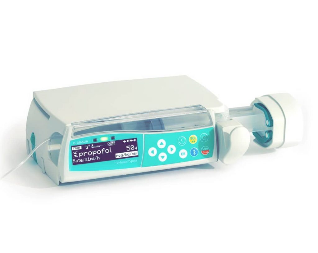
Система применяется для введения медикаментов, предназначенных для инфузионной терапии, включая анестетики, седативные, анальгетики, катехоламины, антикоагулянты и пр.; кровь и компоненты крови; полное парентеральное питание (TPN); жиры; энтеральные смеси, но не ограничивается только ими. Автоматизированная шприцевая инфузионная система Перфузор Спэйс Б. Браун предназначена для применения подготовленным медицинским персоналом в стационарных и амбулаторных лечебных учреждениях, на дому и в санитарном транспорте. Решение о применении данной системы должно приниматься квалифицированным медицинским персоналом на основании ее свойств и технических характеристик.
Производитель Perfusor Space B Braun
Производитель Перфузор Спэйс Б. Браун – B. Braun Melsungen AG, Германия. Представительство в России Б. Браун Медикал ООО, Санкт-Петербург Россия, тел. (812) 320-40-04.
Perfusor Space: Обзор
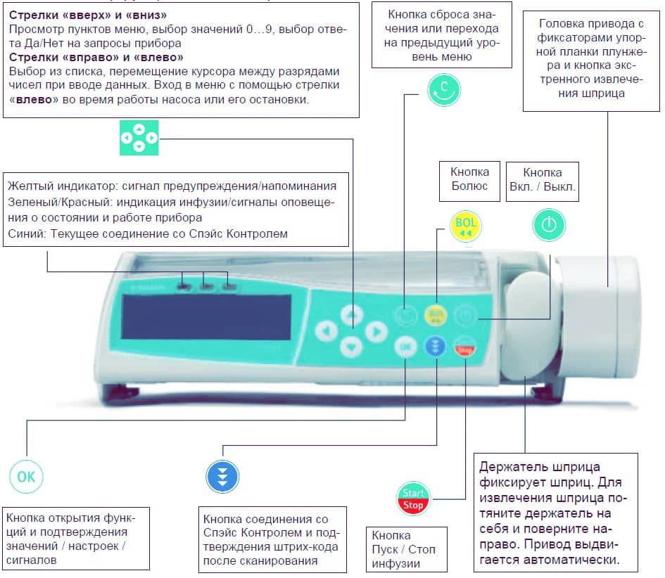
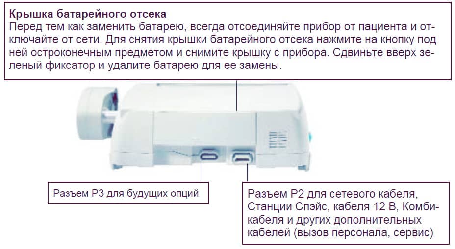
Ниже представлено описание кнопок и деталей автоматизированной шприцевой инфузионной системы Perfusor Space B Braun.
Вид спереди
Вид сзади
Фиксация шприца
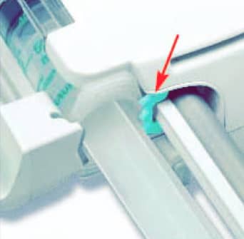
Вытяните и поверните вправо держатель шприца для открытия зеленого осевого фиксатора (см. стрелку). Перед закрытием держателя установите упорную планку цилиндра шприца вертикально в паз слева от осевого фиксатора. Убедитесь в правильном положении шприца. Не касайтесь фиксатора штока при закрытии держателя шприца.
Фиксация универсального зажима
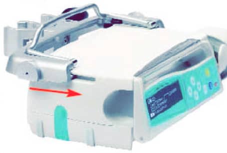
Совместите пазы в верхней части насоса с направляющими универсального зажима и двигайте рамку универсального зажима вперед до щелчка фиксатора. Для отсоединения, нажмите на кнопку извлечения на рамке, опустите транспортную ручку рамки универсального зажима и сдвиньте рамку назад.
Соединение Perfusor Space
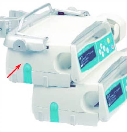
До трех насосов (Инфузомат Спэйс B braun или Перфузор Спэйс B braun) с модулем Спэйс Контроль могут стыковаться в единый блок. Остерегайтесь внешнего механического воздействия. Для соединения приборов совместите пазы нижнего насоса с направляющими верхнего и двигайте нижний насос назад до щелчка фиксатора и сопоставления зеленых кнопок друг под другом. Для отсоединения, нажмите на зеленый боковой фиксатор на верхнем насосе и выдвиньте нижний насос.
Фиксация на стойке
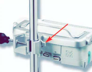
Установите зажим на вертикальной стойке и надежно закрутите винтовой фиксатор. Для снятия, открутите фиксатор. Фиксация на горизонтальной стойке: нажмите на рычаг и вращайте рамку в нужную сторону до фиксации в новом положении со щелчком. Для смены положения снова отожмите рычаг.
Управление Perfusor Space
- Первичный инструктаж по работе с Перфузором Спэйс проводится представителем Б. Браун или уполномоченным лицом. После обновления программного обеспечения Пользователь должен быть проинформирован об изменениях в работе прибора и принадлежностей, описанных в Руководстве по применению.
- Убедитесь, что прибор надежно установлен и закреплен. Не устанавливайте насос над пациентом.
- Перед применением осмотрите насос для исключения повреждений, некомплекта или загрязнений, проверьте аудиовизуальные сигналы самотестирования.
- Подключение к пациенту разрешается только после того, как шприц правильно установлен в насос, зафиксирован захватами привода и линия заполнена раствором. Перекрывайте соединение во время смены шприца для предупреждения неправильного дозирования лекарства.
- Выберите шприц/катетер сообразно предстоящему применению.
- Установите инфузионную линию, избегая перегибов.
- Рекомендуется менять расходные материалы каждые 24 часа (или в соответствие с государственными гигиеническими нормативами).
- Установка в медицинских помещениях должна соответствовать существующим требованиям (напр. VDE 0100, VDE 0107 или постановлениям IEC). Соблюдайте установленные требования и нормативы по безопасности.
- Для предупреждения риска взрыва, не используйте насос в зоне применения огнеопасных анестетиков.
Безопасность пациента
- Сравните введенные параметры с данными экрана. Начинайте инфузию только при полном соответствии параметров.
- При использовании системы вызова персонала, рекомендуется ее проверка после подключения инфузионных насосов.
- Оберегайте прибор и кабель питания от воздействия влаги.
- Не держите насос за привод при переноске.
- В случае падения насоса или внешнего силового воздействия на него, прибор должен быть проверен сервисной службой.
- Данные, отображаемые на экране должны всегда проверяться персоналом до принятия следующего клинического решения.
- Применение насоса как мобильного устройства (при домашнем уходе, внутри- и внебольничной транспортировке пациента): Убедитесь, что прибор надежно установлен и закреплен. Смена положения и сильное сотрясение могут привести к незначительным изменениям точности инфузии.
- При проведении инфузионной терапии в критических ситуациях, обязателен дополнительный мониторинг пациента.
- Избегайте внешнего воздействия на привод во время инфузии.
- При введении высокоактивных лекарств, подготовьте второй насос с тем же лекарством.
- Независимо от заданных мягких ограничений, вводимые значения должны соответствовать клиническому состоянию данного пациента.
- При изменении параметров, влияющих на расчет дозы, значение скорости всегда будет меняться, а значение дозировки будет скорректировано.
Рекомендации по применению
- Используйте только устойчивые к давлению линии (мин. 2 бар / 1500 mmHg).
- При подсоединении нескольких инфузионных линий к одному венозному доступу не исключается вероятность взаимного влияния линий.
- Касательно возможной несовместимости оборудования и лекарств, обратитесь к соответствующей информации производителей.
- Используйте только совместимые комбинации приборов, аксессуаров, рабочих компонентов и одноразовых принадлежностей с винтовым соединением.
- Использование несовместимых одноразовых принадлежностей может влиять на технические характеристики прибора.
- Подключаемые электроприборы должны соответствовать требованиям IEC/EN (напр. IEC/EN 60950 для оборудования по обработке данных). Пользователь несет всю ответственность за конфигурацию системы при подключении дополнительного медицинского оборудования. Должен быть принят во внимание международный стандарт IEC/EN 60601-1-1.
Список лекарств
До 720 наименований лекарств, включая параметры инфузии и информацию о лекарстве, могут быть сохранены в 15 категориях. Загрузка списка в насос может быть произведена с помощью отдельной компьютерной программы “Drug List Editor Space” (Редактор Списка Лекарств Спэйс).
Список лекарств доступен из Меню Пуск и Меню Специальные функции. Перед началом применения Списка, Пользователь должен убедиться, что Список лекарств в насосе соответствует данной группе пациентов. Наименование Списка лекарств будет отображено на экране насоса.
Существует несколько способов вызова Списка лекарств из Меню для последующего применения. Это возможно как во время инфузии, так и при остановке насоса.
С одной стороны, наименование лекарства со всеми параметрами инфузии может быть выбрано из Списка лекарств. С другой стороны, если скорость, объем и/или время уже были заданы в Главном меню, загружаются наименование лекарства и вновь заданные параметры инфузии. Если расчет дозы уже начат, последующее использование наименования лекарства из списка все равно возможно.
Блок данных
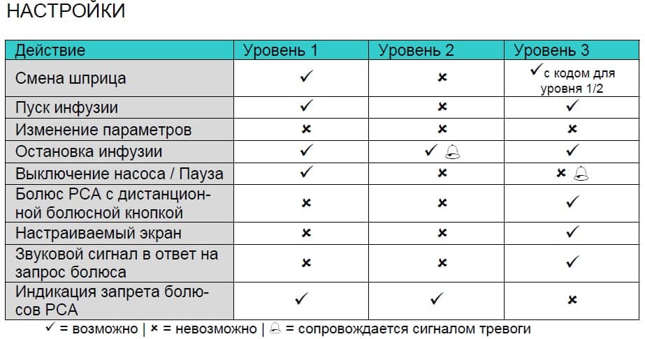
Функция Блок данных защищает прибор от несанкционированного доступа. Четырехзначный код (по умолчанию 9119), который может быть изменен через сервисную программу, активирует эту функцию. Существует три уровня защиты.
Уровень 1
Изменение значений, как и болюсная инфузия недоступны, но можно произвести смену шприца. Возможна навигация по разделам меню и проверка состояния насоса в меню Статус. Пуск, остановка и выключение насоса доступны.
Уровень 2
Этот уровень имеет те же характеристики, что и Уровень 1, но в дополнение к предыдущему, не позволяет произвести смену шприца. Для того, чтобы предотвратить активацию сигнала тревоги «Блок данных», необходимо ввести правильный код в течение 20 секунд после остановки насоса. Смена системы и выключение насоса возможны только после ввода правильного кода.
Уровень 3
Этот уровень позволяет начать и остановить инфузию, а также выключить насос. Код для этого уровня может быть различным для разных лекарств и устанавливается в Списке лекарств. Смена шприца, тем не менее, возможна с использованием кодов, установленных для двух предыдущих уровней.
Обзор различий между уровнями 1, 2 и 3 дан в таблице.
Сигналы и тревоги Perfusor Space B Braun
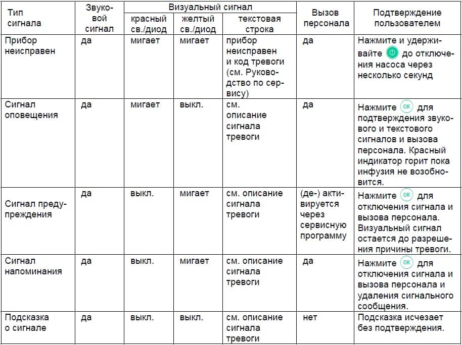
Перфузор Спэйс б браун оснащен звуковой и визуальной сигнализацией тревоги.
Сигналы неисправности Perfusor Space B Braun
При появлении сигнала неисправности прибора инфузия немедленно прекращается. Нажмите кнопку вкл/выкл для отключения прибора. Затем включите прибор снова. При повторном сигнале тревоги, отсоедините насос от пациента, откройте переднюю дверцу насоса и удалите шприц. Прибор необходимо передать в сервисную службу.
Сигналы предупреждения Perfusor Space B Braun
Сигналы предупреждения подаются за несколько минут (в зависимости от сервисных установок) перед сигналами оповещения. Сигнал предупреждения включает звуковой тон, мигающий желтый индикатор и активирует систему вызова персонала (опция). Текстовое сообщение зависит от причины тревоги. Звуковой тон и система вызова персонала отключаются нажатием кнопки «ОК». Экран и индикатор остаются в режиме предупреждения вплоть до отключения сигнала оповещения. Во время подачи сигнала предупреждения инфузия не прерывается.
Шприц почти введен
В шприце осталось очень мало жидкости.
Объем почти введен
Введение заданного объема близко к завершению.
Время истекает
Заданное время инфузии скоро истечет.
Батарея разряжается
Батарея почти разряжена.
KVO активен
Объем введен/Время истекло и насос продолжает инфузию в режиме KVO — Открытая вена.
Ошибка соединения
Насос установлен в систему, хотя бы один из приборов в которой несовместим или неисправен. Применение этого прибора в системе не разрешается. Систему необходимо передать для проверки в сервисную службу.
Таймер на экране ведет обратный отсчет оставшегося времени ( в зависимости от сервисной настройки, от 3 до 30 мин). После этого насос подает сигнал оповещения.
Сигналы оповещения Perfusor Space B Braun
Сигналы оповещения приводят к прерыванию инфузии. Подается звуковой сигнал, мигает красный индикатор и активируется система вызова персонала. На экране появляется сообщения «Тревога» и информация о причине сигнала тревоги. Звуковой сигнал и система вызова персонала могут быть отключены кнопкой «ОК». Коррекция должна быть произведена в соответствие с причиной сигнала тревоги.
Шприц пуст
В шприце не осталось жидкости. Из-за различий в допусках шприцев разных производителей, незначительное количество раствора в шприце может оставаться. Попытка продолжить инфузию приводит к полному опорожнению шприца и отключению через датчик давления. Выполните смену шприца.
Объем введен
Заданный объем введен. Продолжите инфузию или введите новые параметры.
Время истекло
Заданное время инфузии истекло. Продолжите инфузию или введите новые параметры.
Батарея разряжена
Батарея разряжена. Подключите прибор к сети и/или замените батарею. Сигнал о разрядке батареи длится 3 минуты, после этого насос автоматически отключается.
KVO остановлен
Время работы в режиме KVO истекло. Продолжите инфузию или введите новые параметры.
Высокое давление
Обнаружена окклюзия в системе. Достигнут установленный уровень давления. Насос автоматически снижает скорость введения. Проверьте отсутствие петель и перегибов инфузионной линии, проходимость инфузионного фильтра и в/в катетера. Увеличьте уровень окклюзионного давления, если необходимо. Из-за различия в допусках шприцев разных производителей, тревога по давлению может быть обусловлена высокой силой трения между поршнем и цилиндром.
Шприц установлен неверно
Упорные планки цилиндра и штока установлены неправильно.
Держатель шприца
Держатель шприца быль открыт во время инфузии. Закройте держатель шприца.
Крышка батарейного отсека удалена
Крышка батарейного отсека установлена неправильно. Переустановите крышку до щелчка.
Привод заблокирован
Внешние помехи препятствуют движению привода. Устраните все внешние помехи.
Откалибруйте прибор
Параметры калибровки насоса были изменены (например, после обновления программного обеспечения). Выполните калибровку через сервисную программу. Выполняется Сервисной службой.
Захват неисправен
Была нажата кнопка экстренного извлечения шприца и захваты были разведены вручную. Удалите шприц и обратитесь в Сервисную службу.
Планка штока не зафиксирована
Планка штока шприца не контактирует с датчиком давления насоса. Проверьте систему на наличие отрицательного давления и устраните причину.
Время паузы истекло
Установленное время паузы истекло. Задайте новое время паузы или возобновите предыдущую инфузию.
Батарея не установлена
Использование насоса без батареи невозможно. Отключите прибор и установите батарею.
Данные сброшены
Данные инфузии и насоса не возможно восстановить. Введите данные инфузии и настройки насоса заново.
Данные инфузии сброшены
Параметры инфузии не возможно восстановить. Введите параметры инфузии заново.
Блок данных
Была попытка остановить или отключить насос без ввода кода. Введите правильный код для соответствующего продолжения инфузии или выключите насос.
Красный индикатор не гаснет до возобновления инфузия или выключения насоса.
Если на экране появляется символ гаечного ключа и/или одновременно мигают желтый, красный и синий индикаторы – насос находится в сервисном режиме и его использование для лечения пациентов запрещено. Насос должен быть проверен сервисной службой.
Сигналы напоминания Perfusor Space B Braun
Сигналы напоминания подаются в двух случаях:
- Шприц установлен, инфузия не начата, значения не введены и прибор не работает в течение 2 минут. Включается звуковая сигнализация, мигает желтый индикатор и активируется система вызова персонала. Сообщение на экране «Сигнал напоминания!»; Сообщение на экране «Ввод параметров не завершен!». Для прекращения подачи сигнала тревоги нажмите «ОК» и продолжите ввод параметров инфузии и настроек насоса.
- Ввод данных начат, но не завершен или не подтвержден. Другая причина – шприц не установлен. Включается звуковая сигнализация, сообщение на экране «Значение не принято», мигает желтый индикатор и активируется система вызова персонала. Для прекращения подачи сигнала тревоги нажмите «ОК» и продолжите ввод параметров инфузии.
Подсказки о причинах сигналов тревоги
При некорректном вводе параметров, на экране появляются соответствующие подсказки, например «Внимание! Значение скорости превышает допустимое»; «Значение не может быть изменено». Включается звуковая сигнализация. Подсказки исчезают через несколько секунд и их подтверждение не требуется.
Работа от батареи и обслуживание
Перфузор Спэйс оснащен современной NiMH батареей. Время работы насоса с новой батареей составляет 8 часов при скорости инфузии 25 мл/ч. Для оптимальной работы аккумулятора, насос имеет защиту от перегрузки и полной разрядки. Батарея заряжается при включении прибора в сеть. При отключении от сети или в случае падения напряжения, насос автоматически переходит на питание от батареи.
Перед длительным хранением насоса (более 2-х недель без использования), батарея должна быть полностью заряжена, а затем извлечена из насоса. Перед извлечением (сменой) батареи всегда отсоединяйте насос от пациента и отключайте прибор.
Индикатор заряда батареи отображается на экране (низкий, средний, полный заряд). Для получения более детальной информации о состоянии батареи (время работы в часах и минутах) необходимо в меню «Статус» войти в раздел «Батарея».
Самотестирование батареи Perfusor Space B Braun
Если символ батареи мигает во время работы от сети, батарея либо разряжена, либо быстро разряжается. В этом случае насос не должен отключаться от сети. Если необходимо экстренно отключить насос от сети, убедитесь, что остаточный заряд батареи достаточен для применения. Если символ батареи мигает непрерывно (>1ч), батарея должна быть проверена техническим персоналом и замене-на при необходимости.
Оптимальное использование батареи
Факторы, влияющие на срок службы батареи:
- окружающая среда;
- меняющаяся нагрузка (напр. частая подача болюсов).
Срок службы батареи можно увеличить путем ее регулярной зарядки и разрядки. Для этого насос должен работать от батареи до появления сигнала тревоги о ее разрядке. После этого прибор необходимо подключить к сети минимум на 6 часов. Рекомендуется выполнять данную процедуру один раз в месяц.
Кроме того:
- Если возможно, заряжайте батарею только после ее полной разрядки.
- Если батарея, которая не разряжена полностью, заряжается несколько раз, ее емкость может уменьшиться. Первоначальная емкость может быть восстановлена при полной разрядке и последующей зарядке батареи.
- При нормальных температурных условиях батарея может быть заряжена и разряжена приблизительно 500 раз, после чего длительность ее работы снижается.
- При отключении насоса от сети батарея медленно разряжается. Это происходит даже, когда насос не работает. Первоначальная емкость может быть достигнута после нескольких циклов зарядки и разрядки.
- Время работы батареи может быть определено только при непрерывной работе насоса с полностью заряженной батареей при комнатной температуре. Отображаемое на экране насоса приблизительное время работы батареи основывается на текущей скорости инфузии. При длительном сроке использования, реальное время работы батареи снижается.
Батареи могут взрываться и протекать при вскрытии или сжигании. Соблюдайте правила утилизации!
Обслуживание батареи Perfusor Space B Braun
Для точной регулировки емкости батареи необходимо ее циклическое обслуживание. Насос запрашивает Пользователя о проведении обслуживания батареи каждые 30 дней. В режиме обслуживания батареи определяется возможная потеря емкости (например, из-за старения батареи) и затем емкость и время работы от батареи пересчитываются заново. После длительного хранения или длительной работы без обслуживания батареи, может случиться так, что время подачи предупредительного сигнала больше не будет поддерживаться. В этом случае необходимо проведение обслуживания батареи.
Для инициализации полной разрядки батареи на экране появляется запрос «Обслуживание батареи» и отображается кнопка «ОК». Для того, чтобы запустить процесс разрядки батареи, нажмите «ОК» и «вверх». При включении насоса процесс прерывается. Если обслуживание батареи необходимо продолжить, нужно повторно активировать режим обслуживания. После полной разрядки батареи происходит ее полная зарядка. Полное обслуживание батареи длится приблизительно двенадцать часов.
Примите во внимание, что время работы от батареи может быть меньше, если обслуживание батареи не завершено.
Технические характеристики Perfusor Space B Braun
Ниже указаны технические характеристики насоса Perfusor Space B.Braun.
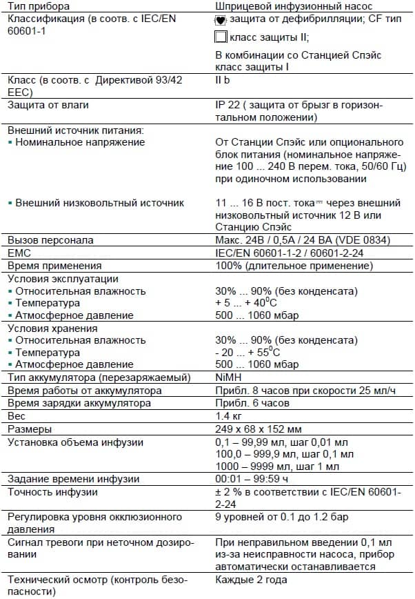
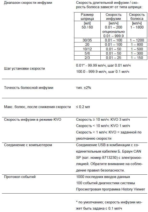
Гарантия Perfusor Space B Braun
Компания Б. Браун предоставляет 24 месяца гарантии, с момента поставки на каждый Перфузор Спэйс (12 месяцев на каждый аккумулятор (Battery Pack SP)). Гарантия предусматривает ремонт или замену отдельных частей, вышедших из строя в результате конструкторских или производственных ошибок, а так же дефектов материала. Срок действия гарантии прекращается в случае модернизации или ремонта, проведенных Пользователем или посторонними лицами.
Гарантия не распространяется на устранение дефектов, вызванных неправильным / неумелым обращением или нормальным износом прибора.
Регулярная проверка Perfusor Space B Braun
Проверяйте чистоту, комплектность, отсутствие повреждений. Используйте прибор только согласно Руководству по применению. При каждом включении проверьте: самотестирование, звуковой сигнал, индикацию работы и сигнализацию.
Уход Perfusor Space B Braun
Очищайте поверхность насоса с использованием мыльного раствора. Не рекомендуется применять распылители в местах контакта с электричеством. Рекомендуется: средство для протирания, например Мелисептол фирмы Б. Браун. После очистки прибор должен высохнуть в течение как минимум одной минуты. Не распыляйте в отверстия прибора. Соблюдайте инструкции по утилизации использованных расходных материалов и уходу за батареями и принадлежностями. Увеличительное стекло передней крышки и экран протирайте мягкой салфеткой. Не используйте Гексакварт.
Принадлежности и каталожные номера Perfusor Space B Braun
Б.Браун Перфузор Спэйс (871 3030)
Станция Спэйс (871 3140)
Станция Спэйс предназначена для установки до четырех насосов.
Верхняя крышка СпэйсКавер стандарт (871 3147)
Верхняя крышка СпэйсКавер комфорт (871 3145)
Верхняя крышка предназначена для установки на Станцию Спэйс. Крышка имеет встроенную ручку для переноски Станции. СпэйсКавер комфорт дополнительно оснащена центральной сигнализацией с блоком управления и сигнальными индикаторами.
Универсальный зажим Спэйс (871 3130)
Предназначен для фиксации до трех насосов Б. Браун Спэйс и одного модуля Спэйс Контроль и их стыковки в единый блок.
Блок питания Спэйс (871 3110A)
Обеспечивает питание от сети для одного насоса или для модуля Спэйс Контроль.
Комби — кабель Спэйс 12 В (871 3133)
Комби – кабель Спэйс позволяет объединить до трех насосов. Все насосы могут быть подключены через блок питания Спэйс или соединительный кабель 12 В.
Перезаряжаемая батарея Спэйс (871 3180)
Интерфейсный кабель CAN Спэйс (871 3230)
Интерфейсный кабель CAN Спэйс требуется для соединения Станции Спэйс / насоса Спэйс с компьютером (для сервисных целей).
Соединительный кабель Спэйс 12 В (871 3231)
Кабель Спэйс для системы вызова персонала (871 3232)
Используйте указанный соединительный кабель для подключения насоса Перфузор Спэйс к системе вызова персонала. Подключение к системе вызова персонала необходимо для выполнения требований VDE 0834.
Оригинальные шприцы Perfusor Space B Braun
- Шприц Перфузор 50 мл без иглы, ЛЛ (872 8844F);
- Шприц Перфузор 50 мл c иглой, ЛЛ (872 8810F);
- Шприц Перфузор 50 мл c иглой и фильтром, ЛЛ (872 8852F);
- Шприц Перфузор 50 мл c иглой и фильтром, светозащитный, ЛЛ (872 8828F);
- Шприц Перфузор 20 мл без иглы, ЛЛ (872 8615);
- Шприц Перфузор 20 мл c иглой, ЛЛ (872 8623);
- Шприц Омнификс 50/60 мл, ЛЛ (461 7509F);
- Шприц Омнификс 30 мл, ЛЛ (461 7304F);
- Шприц Омнификс 20 мл, ЛЛ (461 7207V);
- Шприц Омнификс 10 мл, ЛЛ (461 7100V);
- Шприц Омнификс 5 мл, ЛЛ (461 7053V);
- Шприц Омнификс 2 мл, ЛЛ (461 7029V).
Оригинальные линии Perfusor Space B Braun
- Линия Перфузор, ПВХ, 50 см (825 5172);
- Линия Перфузор, ПВХ, 150 см (872 2960);
- Линия Перфузор, ПВХ, 200 см (872 2862);
- Линия Перфузор, ПВХ, 250 см (825 5490);
- Линия Перфузор, ПВХ, 300 см (825 5253);
- Линия Перфузор, ПЭ, 50 см (825 5059);
- Линия Перфузор, ПЭ, 100 см (825 5067);
- Линия Перфузор, ПЭ, 150 см (872 2935);
- Линия Перфузор, ПЭ, 200 см (872 3060);
- Линия Перфузор, ПЭ, 250 см (827 2565);
- Линия Перфузор, ПВХ, 150 см, безыгольный коннектор Сэйфсайт (872 2820);
- Линия Перфузор, ПВХ, 200 см, инъекционный фильтр 0,22 мкм (872 3001);
- Линия Перфузор, ПВХ, 168 см, PCA, с возвратным клапаном (872 6019);
- Линия Перфузор, тип МР, ПВХ, 75 см, с перекидной гайкой (872 2870);
- Линия Перфузор, тип МР, ПВХ, 150 см, с перекидной гайкой (825 5504);
- Линия Перфузор, ПЭ, 150 см, светозащитная (872 3010).
Скачать инструкцию на Perfusor Space B Braun
Скачать инструкцию и другую документацию на Perfusor Space B Braun можно здесь.
Руководство пользователя ( user manual ) на русском языке Perfusor Space B Braun скачать.
Сервисная инструкция ( service manual ) на английском языке Perfusor Space B Braun скачать.
Регистрационное удостоверение Perfusor Space B Braun скачать.
Так же смотрите Space Control, Инфузионный насос DI 2000 Medifusion, Инфузионный насос Aitecs DF-12M.

Perfusor® Space
Service Manual
Version 1.3 English

0
|
This Service Manual is valid for: |
Designation |
Part No. |
|
Infusion syringe pump Perfusor® Space . . . . . . . . . . . |
. 0871 3030 |
|
|
This Service Manual is available under |
Designation |
Part No. |
|
the following part number: |
Service Manual Perfusor® Space, English. . . . . . . . . . . |
8713 9020 |
|
Languages of this Manual |
The Service Manual for this unit can be supplied in the following |
|
|
languages: |
||
|
Designation |
Part No. |
|
|
Service Manual Perfusor® Space, German . . . . . . . . . . |
8713 9010 |
|
|
Service Manual Perfusor® Space, English (US). . . . . . |
8713 9020U |
|
|
Service Manual Perfusor® Space, French . . . . . . . . . . . |
8713 9030 |
|
2 |
Perfusor® Space, 1.2 gb |

Table of Contents 0
|
Important Preliminary Remarks |
Service Work |
Page |
0 — 5 |
|
Technical Safety Checks |
Page |
0 — 5 |
|
|
Current Versions |
Page |
0 — 5 |
|
|
Revision Service |
Page |
0 — 5 |
|
|
Quality Management |
Page |
0 — 6 |
|
|
Checks and Repair |
Page |
0 — 6 |
|
|
Notes on ESD |
Page |
0 — 6 |
|
|
Spare Parts and Test Equipment |
Page |
0 — 7 |
|
|
Setting Off |
Page |
0 — 7 |
|
|
Contact Persons |
Technical Training |
Page |
0 — 11 |
|
Entry for Technical Training |
Page |
0 — 11 |
|
|
Ordering of Spare Parts and Test Equipment |
Page |
0 — 11 |
|
|
Service Hotline International |
Page |
0 — 11 |
|
|
Return of Spare Parts and Test Equipment |
Page |
0 — 11 |
|
|
Safety Officer |
|||
|
(§ 30 MPG) |
Page |
0 — 11 |
|
|
Translation |
Page |
0 — 11 |
|
|
System Overview |
Description |
Page |
1 — 1 |
|
System Overview |
Page |
1 — 1 |
|
|
Physical Construction |
Page |
1 — 2 |
|
|
Function |
Page |
1 — 3 |
|
|
Unit Software |
Page |
1 — 6 |
|
|
Service Program |
Page |
1 — 7 |
|
|
Technical Data |
Page |
1 — 12 |
|
|
Options |
Page |
1 — 12 |
|
|
Accessories |
Page |
1 — 12 |
|
|
Unit Diagnosis / Calibration |
General |
Page |
2 — 1 |
|
Alarms and Error Codes |
Page |
2 — 3 |
|
|
The Most Important Error Modes |
Page |
2 — 8 |
|
|
Device Check |
Page |
2 — 9 |
|
|
Calibration |
Page |
2 — 14 |
|
|
Procedural Instructions for Calibration |
Page |
2 — 14 |
|
|
Trouble Shooting |
Page |
2 — 29 |
|
|
Disassembly / Assembly |
General |
Page |
3 — 1 |
|
Battery Module |
Page |
3 — 9 |
|
|
Unit Foot |
Page |
3 — 11 |
|
|
Operating Unit |
Page |
3 — 12 |
|
|
Upper Part of Housing |
Page |
3 — 17 |
|
|
Release Button |
Page |
3 — 19 |
|
|
Loudspeaker |
Page |
3 — 19 |
|
|
Drive |
Page |
3 — 20 |
|
|
Syringe Holder with Piston Brake |
Page |
3 — 27 |
|
|
Processor PCB |
Page |
3 — 34 |
|
|
Assembly / Installation |
Page |
3 — 35 |
|
|
Checks after Repair |
Page |
3 — 47 |
|
Perfusor® Space, 1.0 gb |
0 — 3 |

|
Servicing the Unit |
Cleaning |
Page |
4 |
— 1 |
|
Servicing the Battery |
Page |
4 |
— 1 |
|
|
Technical Safety Check (TSC) |
Perfusor® Space 1 |
|||
|
Technical Safety Check (TSC) |
Power Supply SP 1 |
|||
|
Procedural Instructions on the TSC |
Visual Inspection |
Page |
7 |
— 1 |
|
Electrical Safety |
||||
|
according to IEC/EN 60601-1 |
||||
|
or VDE 0750 and VDE 0751 |
Page |
7 |
— 2 |
|
|
Functional Inspection Perfusor® Space |
Page |
7 |
— 3 |
|
|
Functional Inspection Power Supply SP |
Page |
7 |
— 6 |
|
|
Test Equipment and Special Tools |
Test equipment |
Page |
8 |
— 1 |
|
Special Tools |
Page |
8 |
— 3 |
|
|
Spare Parts List |
Page |
9 |
— 1 |
|
|
Revision Documentation |
Description of Version |
Page |
10 |
— 1 |
|
Version List of the Individual Pages |
Page |
10 |
— 1 |
|
|
Index |
Page |
11 |
— 1 |
|
0 — 4 |
Perfusor® Space, 1.0 gb |

Important Preliminary Remarks 0
Service Work |
The present manual is for your information only. The possession of |
|
this manual does not authorize the performance of service work. |
|
|
Service tasks may only be executed by persons, who |
|
|
— have received appropriate training on the system from |
|
|
B. Braun |
|
|
— are included in the revision service |
|
|
— possess the necessary test equipment and mechanical aids, |
|
|
and |
|
|
— fulfill the personal requirements (training and knowledge). |
|
Technical Safety Checks |
The user is obliged to perform or to have performed the Technical |
|
Safety Checks on those medial products for which these checks |
|
|
have been prescribed by the manufacturer and to carry them out |
|
|
according to the indications of the manufacturer as well as the |
|
|
generally approved technical standards while adhering to the |
|
|
periods stated (§ 6 MP BetreibV). |
|
|
B. Braun also recommends training on the Technical Safety |
|
|
Checks, or to perform at least the steps indicated in the current |
|
|
version of the manual, as: |
|
|
— the TSC requires that the instructions in the manuals are |
|
|
observed |
|
|
— the manuals are a reference for measurements |
|
|
— depending on the unit type, the Service Program must be |
|
|
called which may lead to a dangerous unit condition in case |
|
|
of inappropriate operation. Furthermore, a special service |
|
|
connector may be necessary. |
|
Current Versions |
This manual version corresponds to the state when the manual |
|
was written. B Braun reserves the right to make technical |
|
|
modifications. The state of the revision is indicated by the index |
|
|
number in the footer of every page. |
|
Revision Service |
The possession of this manual does not automatically mean |
|
inclusion in the revision service. You will be included in the |
|
|
revision service after: |
|
|
— technical training by B. Braun Melsungen or |
|
|
— a written order placed with the sales department of B. Braun |
|
|
(fee required). |
|
Perfusor® Space, 1.1 gb |
0 — 5 |

|
0 |
Important Preliminary Remarks |
|
Responsibility of the Manufacturer |
The manufacturer, person who assembles, installs or imports the |
|
device can only be held responsible for safety, reliability and |
|
|
performance if |
|
|
— mounting, enhancements, new settings, changes or repairs |
|
|
are carried out by duly authorized persons, |
|
|
— the electrical installation in the corresponding room meets |
|
|
the requirements of the VDE 0107, VDE 0100 part 710 or |
|
|
IEC 60364-7-710 and the national standards, |
|
|
— the device is used in accordance with the instructions for use |
|
|
and the Service Manual, |
|
|
— the Technical Safety Checks are performed at regular |
|
|
intervals, |
|
|
— a current manual which corresponds to the revision state is |
|
|
used when carrying out maintenance, repair and service, |
|
|
— the service technician takes part in the revision service, |
|
|
— the technician has participated in a technical training course |
|
|
for the specific B. Braun unit. |
|
Quality Management |
B. Braun is certified in accordance with DIN EN ISO 9001 and |
|
ISO 13485. This certification also includes maintenance and |
|
|
service. |
|
|
The unit has the CE label. The CE label confirms that the device |
|
|
corresponds to the “Directive of the Council for Medical Products |
|
|
93/42/EC” of June 14, 1993. |
|
Checks and Repair |
Training may only be performed by B. Braun. The possession of the |
|
manual does not authorize the performance of repairs. The |
|
|
instructions on electrostatic sensitive components (ESD |
|
|
standards) must be observed. |
|
|
After repair a device check or diagnosis is to be carried out. |
|
Notes on ESD |
Semiconductors can be destroyed by electrostatic discharge. |
|
Especially MOS components can be damaged by interference from |
|
|
electrostatic fields, even without discharge via contact. This type |
|
|
of damage is not immediately recognizable. Unit malfunctions |
|
|
can even occur after a longer period of operation. |
|
0 — 6 |
Perfusor® Space, 1.1 gb |

|
Important Preliminary Remarks |
0 |
Fig.: 0 — 1
Spare Parts and Test Equipment
Setting Off
Each workstation must be equipped according to the recommendations with the necessary static protective measures, if ESD components or boards are handled.
Each workstation must be equipped with a conductive table surface. The conductive surface, the soldering iron or the soldering stations must be grounded via protective resistors.
Chairs must be of antistatic design. The floor or floor mats should be of electrically conductive material.
Personnel must wear conductive wristbands which are connected to a central ground potential via protective resistors, e.g. the ground contact of a wall outlet. Furthermore it is recommended that personnel wear cotton clothing and electrically conductive shoes to prevent electrostatic charge.
Only use original spare parts from the manufacturer. Do not tamper with assembly groups which can only be exchanged completely. The spare parts required are listed in the repair descriptions.
Service personnel are responsible for the calibration of their test equipment. Original test equipment can be calibrated at the works of B. Braun. Further information is available upon request.
Additional notes and warnings are set off as follows:
Note
Is used for additional or special notes concerning information and working steps.
CAUTION
Is used for working steps which may result in damage to the unit, system or to a connected device.
WARNING
IS USED FOR WORKING STEPS WHICH MAY RESULT IN PERSONAL INJURY.
|
Perfusor® Space, 1.1 gb |
0 — 7 |

|
0 |
Important Preliminary Remarks |
References to chapters are shown as follows (see “Setting Off“ pg. 0 — 7)
References to figures and tables are shown as follows
Fig.: 2 — 3 or Table 2 — 1
References to item numbers in figures are shown as follows (Fig.: 1 — 1 / Item 1)
In this case “Fig.: 1 — 1“ is the figure number and “Item 1“ the item number within the figure.
When the Service Manual is stored as pdf-file, these references are displayed green. Click with the mouse button on a reference to jump to the corresponding source.
Menu commands are described as: Menu File.
|
0 — 8 |
Perfusor® Space, 1.1 gb |

|
Important Preliminary Remarks |
0 |
|
List of Abbreviations |
Abbreviations which are not generally known, but are used in this |
|
|
manual, are listed below. |
||
|
CAN |
Controller Area Network |
|
|
CE |
Communauté Européenne |
|
|
(European Communities) |
||
|
CS |
Calibration Step |
|
|
DIN |
Deutsche Industrie Norm |
|
|
(German Industrial Standard) |
||
|
EN |
European Standard |
|
|
ESD |
Electrostatic Discharge |
|
|
FuP |
Function Microprocessor |
|
|
IEC |
International Electrotechnical |
|
|
Commission |
||
|
ISO |
International Standardization |
|
|
Organization |
||
|
ISP |
Infusomat® Space |
|
|
ISPS |
Infusomat® Space, Silicon |
|
|
ISPP |
Infusomat® Space, PVC |
|
|
KuP |
Monitoring Microprocessor |
|
|
LCD |
Liquid Crystal Display |
|
|
MOS |
Short for the following |
|
|
company name: |
||
|
MOS Technology, Inc. |
||
|
(Commodore Semiconductor |
||
|
Group) |
||
|
PCA |
Patient-Controlled Analgesia |
|
|
PSP |
Perfusor® Space |
|
|
SP |
Space (System) |
|
|
SPC |
SpaceCover |
|
|
SPCC |
SpaceCover comfort |
|
|
SPCS |
SpaceCover standard |
|
|
SPCO |
SpaceCom |
|
|
SPCT |
SpaceControl |
|
|
SPS |
SpaceStation |
|
|
TEMP |
Temperature |
|
|
TS |
Troubleshooting Step |
|
|
TSC |
Technical Safety Checks |
|
Perfusor® Space, 1.2 gb |
0 — 9 |

|
0 |
Important Preliminary Remarks |
|
UTS |
Unit Test Step |
|
VDE |
Verband der Elektrotechnik, |
|
Elektronik und |
|
|
Informationstechnik e.V. |
|
|
(German electrical engineering |
|
|
association) |
|
0 — 10 |
Perfusor® Space, 1.2 gb |

Contact Persons 0
Technical Training |
Via local representative. |
||
Entry for Technical Training |
Application for a technical training course must be made via the |
||
|
responsible representative. |
|||
Ordering of Spare Parts and Test Equipment |
Please contact your local B. Braun subsidary. |
||
|
International Technicians (Intercompany) |
|||
|
Nadja Machal |
|||
|
Fax: |
+49 5661 / 75 — 47 89 |
||
|
e-mail: |
nadja.machal@bbraun.com |
||
Service Hotline International |
Karl Tippel, Tanja Kördel |
||
|
Fax: |
+49 5661 / 71 — 35 26 |
||
|
e-mail: |
karl.tippel@bbraun.com |
||
|
e-mail: |
tanja.koerdel@bbraun.com |
||
Return of Spare Parts and Test Equipment |
B. Braun Melsungen AG |
||
|
Schwarzenberger Weg 73-79 |
|||
|
Wareneingang Werk C |
|||
|
34 212 Melsungen |
|||
|
Germany |
|||
|
Safety Officer |
Dr. Ludwig Schütz |
||
|
(§ 30 MPG) |
e-mail: ludwig.schuetz@bbraun.com |
||
Translation |
Cs2 Informatik GmbH & Co. KG, Germany |
|
Perfusor® Space, 1.3 gb |
0 — 11 |

|
0 — 12 |
Perfusor® Space, 1.0 gb |

System Overview 1
Description |
The Perfusor® Space (PSP) is according to IEC/EN 60601 resp. IEC/ |
|
|
EN 60601-2-24 a transportable infusion syringe pump for |
||
|
administrating fluids in the nutritional therapy and infusion |
||
|
technique as well as for home care applications. |
||
|
The medical specialist must decide on suitability for application |
||
|
on the basis of the warranted properties and the technical data. |
||
System Overview |
The Space system is a modular design of modern infusion |
|
|
technology for stationary, mobile or private use. The key modules |
||
|
and their connection to the peripheral devices are shown in |
||
|
Fig.: 1 — 1. |
||
|
All the pump types, Perfusor® Space, Infusomat® Space and |
||
|
Infusomat® Space P, as well as the other devices of the system are |
||
|
1 |
||
|
of modular design. Up to three pumps can be connected together |
||
|
mechanically using L rails on the bottom of the unit and grooves |
||
|
2 |
on the top. They can then be fastened to a drip stand or |
|
|
appropriate rail using the pole clamp. |
||
|
The SpaceControl module can be used to extend operation. One |
||
|
3 |
single pump can be inserted onto this module. The pump is then |
|
|
connected via connectors to the module. |
||
|
The SpaceStation module allows the set-up of a complete pump |
||
|
system with up to 24 pumps. Up to four pumps can be installed in |
||
|
4 |
every SpaceStation. The pumps are supplied with power via the |
|
|
5 |
integrated power supply and the built-in connectors. The pumps |
|
|
are connected to the optional SpaceCom via these connectors. |
||
|
SpaceControl can also be integrated into the system. |
||
|
Up to six SpaceStations can be set-up as a column with a total of |
||
|
24 pumps. SpaceStation placed next to each other can be |
||
|
Fig.: 1 — 1 Space system |
connected via special connection cables, if the maximum number |
|
|
of 24 pumps in maximum three columns is not exceeded. |
||
|
Legend of fig. 1 — 1: |
SpaceCover Standard or SpaceCover Comfort forms the top of |
|
|
ItemDesignation |
||
|
each column. Alarms are signalled by a row of LEDs and a |
||
|
1 SpaceCover |
||
|
loudspeaker in the SpaceCover Comfort. |
||
2Infusion pump Infusomat® Space
3Infusion syringe pump Perfusor® Space
4SpaceControl
5SpaceStation
|
Perfusor® Space, 1.0 gb |
1 — 1 |

Physical Construction
5
4
3
 6
6
Fig.: 1 — 2 Perfusor® Space
Legend of fig. 1 — 2:
ItemDesignation
|
1 |
Perfusor® Space |
6 |
Connector “P2“ for SpaceStation module, external 12 V DC |
|
2 |
Drive head |
and accessories |
|
|
3 |
Syringe holder with piston brake |
7 Connector “P3“, connection to SpaceControl module |
|
|
4 |
Operating Unit |
8 |
Battery compartment cover |
|
5 |
Syringe area |
|
1 — 2 |
Perfusor® Space, 1.0 gb |

|
The Perfusor® Space housing mainly consists of the bottom part |
|
|
and the upper part. |
|
|
The battery module is inserted in the rear of the housing upper |
|
|
part. The opening is covered by the battery compartment cover. |
|
|
The operating unit is attached to the front of the bottom part with |
|
|
two hinges. This operating unit covers the area for the syringes. |
|
|
The complete drive assembly, consisting of lead screw and drive |
|
|
head with driving tube is located directly behind the syringe area |
|
|
in the bottom part of the housing. The housing bushing for the |
|
|
driving tube is located in the side of the housing. |
|
|
The syringe holder is mounted in the right side of the housing |
|
|
bottom part. |
|
|
The processor PCB with the permanently connected external |
|
|
connectors “P2” and “P3” is located at the bottom of the housing |
|
|
bottom part. |
|
Function |
There are two power options for the Perfusor® Space: |
|
— via the inserted battery module |
|
|
— via an external 12 V DC power supply (e.g. SpaceStation, |
|
|
SpaceControl, an external power supply or from an |
|
|
ambulance car) connected to connector “P2” |
|
|
The voltage supplied is converted to the internal voltages required |
|
|
through a voltage transforming and monitoring circuit on the |
|
|
processor PCB. |
|
|
An independent circuit in the battery module monitors the battery |
|
|
cells and controls their charge condition. |
|
|
The Perfusor® Space is connected to a SpaceControl by connector |
|
|
“P3”. |
|
|
The function processor controls all the functions of the Perfusor® |
|
|
Space. Data is stored in a non-volatile memory which also |
|
|
controls the external data transfer. |
|
|
The control microprocessor monitors all important responses of |
|
|
the function processor to incoming information. If a response |
|
|
does not correspond with that expected by the control |
|
|
microprocessor, an error message is generated and the device is |
|
|
switched to a safe stop state. |
|
|
The drive motor is monitored by a detector for speed and direction |
|
|
of rotation. The extended end position of the drive head is |
|
|
detected by a switch on the processor PCB. |
|
Perfusor® Space, 1.0 gb |
1 — 3 |

The pressure in the infusion system is measured through a strain gauge measuring in the drive head and monitored in the device electronics. The data from the strain gauge is continuously compared with the limit values which are calculated dependent on the selected syringe type and the pressure settings. When the limit values are exceeded an alarm is automatically triggered and the pressure in the infusion system is reduced. The maximum pressure is additionally limited by a second, independent system. This maximum pressure limitation is performed using the motor current control.
The syringe size detection is performed via the syringe holder. The syringe holder is connected to a potentiometer. The syringe size is determined from the resistance of the potentiometer.
The syringe is fixed with the syringe holder and the axial fastening device. The syringe piston is fastened with two claws in the drive head. When a syringe is inserted the syringe piston is held by the piston brake, until the piston has been caught by the claws.
Keyboard and display as well as the syringe area are illuminated.
|
1 — 4 |
Perfusor® Space, 1.0 gb |

|
System Overview |
1 |
|
Fig.: 1 — 3 Block diagram Perfusor® Space |
|
Perfusor® Space, 1.0 gb |
1 — 5 |

Unit Software |
Approved Software Versions |
|||||||||||||||
|
688A030032 |
||||||||||||||||
|
— |
Basic software |
|||||||||||||||
|
Position |
1 |
2 |
3 |
4 |
5 |
6 |
7 |
8 |
9 |
10 |
||||||
|
Digit |
6 |
8 |
8 |
C |
0 |
3 |
0 |
0 |
0 |
1 |
688A030035 |
|||||
|
— |
Improved functions |
|||||||||||||||
|
688A030040 |
||||||||||||||||
|
Revision level |
||||||||||||||||
|
— |
Improved functions |
|||||||||||||||
|
Hardware |
||||||||||||||||
|
Software group |
— |
Languages French and Swedish added |
||||||||||||||
|
688B030002 |
||||||||||||||||
|
Device type: Perfusor® Space |
||||||||||||||||
|
Fig.: 1 — 4 |
— |
Improved functions |
||||||||||||||
|
688B030003 |
||||||||||||||||
|
— |
CAN bus functioning |
|||||||||||||||
|
688C030001 |
||||||||||||||||
|
— |
Dose calculation |
|||||||||||||||
|
— |
Changed CAN log |
|||||||||||||||
|
688D030001 |
||||||||||||||||
|
— Drug list data base |
||||||||||||||||
|
— |
Changed user language |
|||||||||||||||
|
688E030003 |
||||||||||||||||
|
— |
Improved functions |
|||||||||||||||
|
— |
Piggyback |
|||||||||||||||
|
— |
Soft limits |
|||||||||||||||
|
688F030006 |
||||||||||||||||
|
— |
PCA |
|||||||||||||||
|
— |
Changed claw configuration |
|||||||||||||||
|
— |
Optimized alarm handling |
|||||||||||||||
|
688G030002 |
||||||||||||||||
|
— |
Improved functions |
|
1 — 6 |
Perfusor® Space, 1.0 gb |

Service Program
Software Update of the Unit
The instructions for updating the software are supplied with the software itself.
CAUTION
If the device is disconnected while the software is being updated or the device or PC is switched off, a component of the software may be seriously damaged so that repairs are no longer possible. In such a case the software cannot be updated via the PC and the device must be returned to B. Braun.
Approved Version
Note
Please note that text and / or functions of the Service Program may change depending on the software version. The following screen illustrations are only examples and represent the state when the manual was printed.
—0.0.28
—1.0.0
—1.1.2
—1.1.3
—1.1.4
—1.2.1
—1.3.5
—1.5.0
—2.0.1
—3.1.0
—4.0.0
—5.1.0
Starting the Service Program
Note
Installation and further operation of the Service Program is described in its separate instructions for use.
|
Perfusor® Space, 1.0 gb |
1 — 7 |

Fig.: 1 — 5
Fig.: 1 — 6
Fig.: 1 — 7
1.Start the “HiBaSeD.exe” program (History, Barcode, Service, Drug list) on the PC. The Service Program is loaded and started and the initial window of the Service Program is displayed.
2.Read the notes carefully.
3.Mark the field “I accept all conditions” and then the field “Yes” to confirm that you have read the notes.
Note
Click the field “English” to switch the language of the notes over to English.
4.Enter the password and confirm it by clicking the field “Start”.
The Service Program checks the PC interfaces for connected devices of the Space system. Units that were found are displayed for a short moment on the screen.
|
1 — 8 |
Perfusor® Space, 1.0 gb |

The work window of the Service Program appears on the screen. All devices recognized are listed in the left column.
Fig.: 1 — 8
5. Activate the desired device from the list on the left in the work window with a double-click. The device data is then displayed below the device name.
|
Perfusor® Space, 1.0 gb |
1 — 9 |

If the unit software version is not compatible with the Service Program version, a window opens prompting the operator to change the Service Program version. This window displays a compatibility list of the Service Programand unit software versions.
If Service Programand unit software versions are compatible, all the Service Program functions are activated.
Fig.: 1 — 9
Fig.: 1 — 10
|
1 — 10 |
Perfusor® Space, 1.0 gb |

Fig.: 1 — 11
Fig.: 1 — 12
Service Program Version
1.Open the “HiBaSeD“ window via Help Info …. The current version of the Service Program is shown in this window.
2.Close the window by clicking “OK”.
Compatibility List
1.Open the “Unit — Compatibility” window via Help Compatibility. This window displays the compatibility of the HiBaSeD-version and the unit software version.
2.Close the window by clicking “OK”.
Quit the Service Program
1.Exit the Service Program via Application Quit.
2.Disconnect a power supply which might be connected from the unit.
3.Switch off the unit.
4.Remove the battery module.
5.The device can be restarted after appr. 10 seconds.
|
Perfusor® Space, 1.0 gb |
1 — 11 |

Technical Data
Options
Accessories
All technical data is indicated in the instructions for use.
The functions of the individual options are detailed in the instructions for use.
Perfusor® Space
Designation Part No.:
Power supply Euro . . . . . . . . . . . . . . . . . . . . . . . . . . . . 0871 3110A Power supply UK. . . . . . . . . . . . . . . . . . . . . . . . . . . . . . 0871 3111A Power supply USA / Japan . . . . . . . . . . . . . . . . . . . . . . 0871 3112A Power supply Australia. . . . . . . . . . . . . . . . . . . . . . . . . 0871 3113A Power supply South Africa. . . . . . . . . . . . . . . . . . . . . . 0871 3115A
|
Designation |
Part No.: |
|
Charger SP . . . . . . . . . . . . . . . . . . . . . . . . . . . . . . . . . . . |
0871 3170 |
|
battery charging station |
|
|
Connection cable staff call SP. . . . . . . . . . . . . . . . . . . . |
0871 3232 |
|
Power supply cable 12 V . . . . . . . . . . . . . . . . . . . . . . . . |
0871 3231 |
|
for ambulance cars |
|
|
CombiLead SP 12 V . . . . . . . . . . . . . . . . . . . . . . . . . . . . |
0871 3133 |
|
connection cable, pump — pump |
|
|
InterfaceLead SP . . . . . . . . . . . . . . . . . . . . . . . . . . . . . . |
0871 3234 |
|
interface cable RS232 |
|
|
InterfaceLead SP . . . . . . . . . . . . . . . . . . . . . . . . . . . . . . |
0871 3230 |
|
interface cable CAN SP |
|
|
SpaceClamp SP . . . . . . . . . . . . . . . . . . . . . . . . . . . . . . . . |
0871 3130 |
|
The SpaceClamp is a holder attached on beds for one |
|
|
or several Space system pumps. |
|
|
Short stand SP . . . . . . . . . . . . . . . . . . . . . . . . . . . . . . . . |
0871 3135 |
|
Space PCA kit (PCA button) . . . . . . . . . . . . . . . . . . . . . |
0871 3554 |
|
Syringe Anti Removal Cap PSP . . . . . . . . . . . . . . . . . . . |
0871 3556 |
|
1 — 12 |
Perfusor® Space, 1.3 gb |

Unit Diagnosis / Calibration 2
General
WARNING
WHILE TESTING THE UNIT AND TROUBLE SHOOTING THE
OPERATOR/SERVICE TECHNICIAN MUST WORK WITH VOLTAGES
UP TO 115 / 230 V AC. THESE VOLTAGES MAY CAUSE INJURIES
WHICH ARE DANGEROUS TO LIFE AND LIMB. THE NATIONAL AND
INTERNATIONAL SAFETY REGULATIONS ARE TO BE ADHERED TO.
Before each disassembly and assembly of a unit subsystem check the connectors, plug contacts and connections for corrosion and tight fit. These fault types are not described again in the following trouble shooting list.
The following equipment and gauges are necessary for testing the unit and/or performing troubleshooting:
— PC
— Service connector SP
— Service Program HiBaSeD — Interface cable
— Syringe 2 ml / 3 ml — Syringe 10 ml
— Syringe 30 ml
— Diameter gauge 32.0 mm — Diameter gauge 23.4 mm — Diameter gauge 15.7 mm — Diameter gauge 9.0 mm — Length gauge PSP
— Syringe gauge “#Lehre OPS 50“with push-button plate and motor power test adapter for Perfusor® Space
There are pictures of the gauges in Chapter “Special Tools“ ( pg. 8 — 3).
CAUTION
Take special care when carrying out measurements on an open and switched-on unit. Short circuits and wrong measuring methods can cause serious damage to or destroy the subsystems of the device.
|
Perfusor® Space, 1.1 gb |
2 — 1 |

|
2 |
Unit Diagnosis / Calibration |
The unit check, calibration and trouble shooting are subdivided into numbered working steps (Unit Test Step UTS, Calibration Step CS, Trouble Shooting TS) and are based on each other.
Beginning with UTS 1 the operation described here has to be executed. The consequences of the steps performed are listed in the “Function“ column. If the result corresponds to the consequence, the working step must be carried out to which reference is made in the column “If yes”. If the result does not correspond with the function described, the working step in column “If no” is to be executed.
One example is given in Fig.: 2 — 1.
|
UTS |
Activity |
Function |
If yes |
If no |
|
1 |
UTS 2 |
|||
|
2 |
UTS 3 |
TS 1 |
||
|
3 |
UTS 4 |
|||
|
4 |
UTS 5 |
TS 4 |
||
|
5 |
||||
|
Model table 1 |
||||
|
TS |
Activity |
Function |
||
|
1 |
UTS 3 |
TS 2 |
||
|
2 |
TS 3 |
TS 4 |
||
|
3 |
UTS 3 |
|||
|
4 |
UTS 4 |
TS 4 |
||
|
5 |
UTS 4 |
|||
|
Model table 2 |
||||
|
Fig.: 2 — 1 Model tables |
Steps for which additional information is required are described after the table in detail.
|
2 — 2 |
Perfusor® Space, 1.0 gb |

|
Unit Diagnosis / Calibration |
2 |
Alarms and Error Codes
The alarms of the Perfusor® Space are classified in 5 categories. These categories are listed hereafter according to their importance.
—Alarm advice
In case of unacceptable inputs corresponding messages are displayed (e.g. “Caution! Rate out of range“, “The parameter cannot be changed“) and a beep sounds.
—Pre-alarm
Pre-alarms are triggered several minutes (depending on the service settings) before the operating alarms.
—Reminder alarm
A reminder alarm is triggered if the device is not operated for two minutes when input or operation was not finished.
—Operating alarm
In case of an operating alarm the infusion is stopped. An audible signal is released, the red LED flashes and a staff call is triggered. The message “Alarm” and the cause of the alarm appear on the display.
—Device alarm
The most important alarms and error codes as well as their meaning and possible fault clearance are specified in the following lists.
Note
The device should be checked after every repair or service (see “Device Check“ pg. 2 — 9).
|
Perfusor® Space, 1.0 gb |
2 — 3 |

|
2 |
Unit Diagnosis / Calibration |
|
Alarms |
|||
|
Alarm |
Possible Cause |
Fault Clearance |
|
|
1 |
Battery nearly discharged (type: pre- |
The device was not connected to the |
Operate the device with battery until the |
|
alarm) |
mains long enough |
message “Battery discharged“ is |
|
|
displayed and the unit is switched off. |
|||
|
Then connect the unit to the mains for at |
|||
|
least 6 hours. |
|||
|
Battery module defective or too old |
Replace battery module |
||
|
2 |
Battery discharged (type: operating |
The device was not connected to the |
Connect the unit to the mains for at least |
|
alarm) |
mains long enough |
6 hours |
|
|
Battery module defective |
Replace battery module |
||
|
3 |
Battery cover open (type: operating |
The battery compartment cover is |
Insert the battery compartment cover |
|
alarm) |
not correctly closed |
correctly |
|
|
The magnet in the battery |
Exchange the battery compartment cover |
||
|
compartment cover is missing |
|||
|
The battery compartment cover is |
Replace battery module |
||
|
not recognized by the battery |
|||
|
module |
|||
|
4 |
Drive blocked (type: operating alarm) |
The drive was manually blocked |
Eliminate blockage |
|
Driving force too low |
Connect the unit to the mains for at least |
||
|
6 hours and charge battery |
|||
|
Re-calibrate the device |
|||
|
The drive is physically damaged |
Replace drive. |
||
|
5 |
Malfunction of claws (type: operating |
The syringe piston was not |
Select or insert correct syringe type |
|
alarm) |
recognized |
||
|
Loosen the syringe via the emergency |
|||
|
release button in the drive head and |
|||
|
insert again |
|||
|
Re-calibrate the device |
|||
|
The claws or the claw drive are/is |
Replace drive head |
||
|
damaged |
|||
|
6 |
Push-button has no contact (type: |
Negative pressure in the syringe |
See instructions for use |
|
operating alarm) |
system |
||
|
Syringe was removed without |
See instructions for use |
||
|
opening the syringe holder |
|||
|
Push-button sensor defective |
Replace drive head |
||
|
7 |
Device alarm (type: device alarm) |
A serious internal fault was detected in |
Switch device off and on |
|
the system |
|||
|
Carry out a device check (see “Device |
|||
|
Check“ pg. 2 — 9) |
|||
|
Table 2 — 1 Alarms |
|
2 — 4 |
Perfusor® Space, 1.0 gb |

|
Unit Diagnosis / Calibration |
2 |
|
Device Alarms of the Function Processor |
||||
|
Error Code |
Definition |
Possible Cause |
Fault Clearance |
|
|
1 |
1001 … 1013 |
Internal Error |
||
|
2 |
1014 |
Loudspeaker not off |
Loudspeaker connector |
Check the loudspeaker connector |
|
Loudspeaker |
Check the loudspeaker |
|||
|
3 |
1015 |
Loudspeaker lost |
Loudspeaker connector |
Check the loudspeaker connector |
|
Loudspeaker |
Check the loudspeaker |
|||
|
4 |
1016 |
Loudspeaker shorted |
Loudspeaker connector |
Check the loudspeaker connector |
|
Loudspeaker |
Check the loudspeaker |
|||
|
5 |
1017 |
KuP switchoff path defect |
Switch off path |
|
|
(K_SM_CLK) |
||||
|
6 |
1018 |
ADC pressure out of range |
Pressure measurement in drive |
Carry out calibration |
|
head |
||||
|
7 |
1019 |
Internal Error |
||
|
8 |
1020 |
FUP Flash Memory Error Software |
Software |
Update unit software |
|
9 |
1021 |
FUP different version KuP to FuP |
Software |
Update unit software |
|
10 |
1022 |
FUP pressure zero test fail |
Pressure measurement in drive |
Carry out calibration |
|
head |
||||
|
11 |
1023 |
FUP pressure offset test fail |
Pressure measurement in drive |
Carry out calibration |
|
head |
||||
|
12 |
1024 |
FUP EA key closed too long 20sec |
Keyboard defective |
Carry out device check |
|
13 |
1025 |
Internal Error |
||
Table 2 — 2 Device alarms of the function processor
|
Perfusor® Space, 1.0 gb |
2 — 5 |

|
2 |
Unit Diagnosis / Calibration |
|
Device Alarms of the Control Microprocessor |
||||
|
Error Code |
Definition |
Possible Cause |
Fault Clearance |
|
|
1 |
1100 |
Timebase too fast |
Quartz of the processor PCB |
Exchange processor PCB |
|
2 |
1101 |
Timebase too slow |
Quartz of the processor PCB |
Exchange processor PCB |
|
3 |
1102 |
Timebase fail |
Quartz of the processor PCB |
Exchange processor PCB |
|
4 |
1103 |
Keyboard High |
Keyboard defective |
Carry out device check |
|
5 |
1104 |
EA_KEY defect 25sec |
Keyboard defective |
Carry out device check |
|
6 |
1105 |
No keydecode |
Keyboard defective |
Carry out device check |
|
7 |
1106 |
ROM Romtest defect Software |
Software |
Update unit software |
|
8 |
1107 |
ROM Program defect |
Software |
Update unit software |
|
9 |
1108 |
CM State without set |
||
|
K_V_KM_ON |
||||
|
10 |
1109 |
MPU_Test failed |
Software |
Update unit software |
|
11 |
1110 |
RAM_Test failed |
Software |
Update unit software |
|
12 |
1111 |
active reset |
Voltage supply during operation |
|
|
interrupted |
||||
|
13 |
1112 … 1114 |
Internal Error |
||
|
14 |
1115 |
Drive too fast |
Motor drive |
Exchange processor PCB |
|
Recognition of direction of |
||||
|
rotation |
||||
|
15 |
1116 |
Drive too slow |
Motor drive |
Exchange processor PCB |
|
Recognition of direction of |
||||
|
rotation |
||||
|
16 |
1117 … 1118 |
Internal Error |
||
|
17 |
1119 |
lcd backlight on defect |
LC display defective |
Exchange operating unit |
|
18 |
1120 |
lcd backlight off defect |
LC display defective |
Exchange operating unit |
|
19 |
1121 |
red led on defect |
LC display defective |
Exchange operating unit |
|
20 |
1122 |
red led off defect |
LC display defective |
Exchange operating unit |
|
21 |
1123 |
key pressed too long (without EA- |
Keyboard defective |
Carry out device check |
|
Key) 60sec |
||||
|
22 |
1124 … 1127 |
Internal Error |
||
|
23 |
1128 |
Drive motion rightless forward |
Motor drive |
Exchange processor PCB |
|
Recognition of direction of |
||||
|
rotation |
||||
|
24 |
1129 |
Drive motion rightless backward |
Motor drive |
Exchange processor PCB |
|
Recognition of direction of |
||||
|
rotation |
||||
|
25 |
1130 … 1200 |
Internal Error |
||
Table 2 — 3 Device alarms of the control microprocessor (Part 1 of 2)
|
2 — 6 |
Perfusor® Space, 1.0 gb |

|
Unit Diagnosis / Calibration |
2 |
|
Error Code |
Definition |
Possible Cause |
Fault Clearance |
|
|
26 |
1201 |
different version FuP to KuP |
Software |
Update unit software |
|
Software |
||||
|
27 |
1202 |
E_ERROR_STEPMOTOR_1 Phase |
Drive motor, lead screw |
Exchange processor PCB |
|
not ok |
||||
|
28 |
1203 |
E_ERROR_STEPMOTOR_2 Current |
Motor drive |
Carry out calibration |
|
value not 0x55 |
Recognition of direction of |
|||
|
rotation |
||||
|
29 |
1204 |
E_ERROR_STEPMOTOR_3 |
Motor drive |
Carry out calibration |
|
K_SM_CLK defect |
Recognition of direction of |
|||
|
rotation |
||||
|
30 |
1205 |
E_ERROR_STEPMOTOR_4 Phase |
Motor drive |
Carry out calibration |
|
not ok |
Recognition of direction of |
|||
|
rotation |
||||
|
31 |
1206 |
E_ERROR_STEPMOTOR_5 |
Motor drive |
Carry out calibration |
|
Current value not 0 |
Recognition of direction of |
|||
|
rotation |
||||
|
32 |
1207 |
E_ERROR_STEPMOTOR_6 Current |
Motor drive |
Carry out calibration |
|
value not 0x55 |
Recognition of direction of |
|||
|
rotation |
||||
|
33 |
1208 |
E_ERROR_STEPMOTOR_7 Current |
Motor drive |
Carry out calibration |
|
value not 0xAA |
Recognition of direction of |
|||
|
rotation |
||||
|
34 |
1209 |
E_ERROR_STEPMOTOR_8 Phases |
Motor drive |
Carry out calibration |
|
not 0 |
Recognition of direction of |
|||
|
rotation |
||||
|
35 |
1210 |
E_ERROR_DCMOTOR_1 |
Piston brake drive motor def. |
|
|
Claw drive in drive head defective |
||||
|
36 |
1211 |
E_ERROR_DCMOTOR_2 |
||
|
Piston brake light barrier def. |
||||
|
37 |
1212 |
E_ERROR_DCMOTOR_3 |
||
|
38 |
1213 |
E_ERROR_DCMOTOR_4 |
||
|
39 |
1214 |
E_ERROR_DCMOTOR_5 |
||
|
40 |
1215 |
no V_MOT |
Voltage transformer defective |
Exchange processor PCB |
|
41 |
1216 |
overvoltage test fail |
||
|
42 |
1217 |
no V_MOT |
||
|
43 |
1218 |
undervoltage test fail |
||
|
44 |
1220 |
syringeholder defect |
Syringe holder or potentiometer |
Replace syringe holder |
|
def. |
Exchange processor PCB |
|||
|
45 |
1221 |
syringe change timeout |
||
|
46 |
1237 … 1238 |
Internal Error |
||
|
47 |
1239 |
plunger plate sensor defect |
Pressure measurement in drive |
Replace drive head |
|
head |
||||
|
48 |
1240 … 1254 |
Internal Error |
||
Table 2 — 3 Device alarms of the control microprocessor (Part 2 of 2)
|
Perfusor® Space, 1.0 gb |
2 — 7 |

|
2 |
Unit Diagnosis / Calibration |
The Most Important Error Modes |
The following list specifies the most important error modes and |
||||
|
their clearance. |
|||||
|
Note |
|||||
|
The device must be checked after every repair or service (see |
|||||
|
“Device Check“ pg. 2 — 9). |
|||||
|
Error |
Possible Cause |
Fault Clearance |
|||
|
1 |
The battery module discharges too fast |
The device was not used for a longer time. |
Discharge and charge battery module |
||
|
The battery module was not discharged |
several times |
||||
|
and charged at regular intervals. |
Replace battery module |
||||
|
Table 2 — 4 |
|
2 — 8 |
Perfusor® Space, 1.0 gb |

|
Unit Diagnosis / Calibration |
2 |
Device Check
|
UTS |
Activity |
Function |
If yes |
If no |
|
|
1 |
The device is inserted in a SpaceStation or |
UTS 2 |
UTS 3 |
||
|
connected to a SpaceControl. |
|||||
|
2 |
Remove the device. |
UTS 4 |
|||
|
3 |
Loosen all connections from the device. |
UTS 4 |
|||
|
4 |
Remove syringe and close syringe holder. |
UTS 5 |
|||
|
5 |
Plug service connector SP on connector “P2”. |
UTS 6 |
|||
|
6 |
Connect power supply to the device via service |
All LEDs light up for a short moment. |
UTS 7 |
TS 1 |
|
|
connector SP. |
|||||
|
7 |
The battery charge state and the mains connection |
UTS 8 |
TS 5 |
||
|
are displayed at the top left of the LC display |
|||||
|
(without lighting). |
|||||
|
8 |
Switch on unit. |
All LEDs light up (from left: yellow, green, blue). |
UTS 9 |
TS 5 |
|
|
9 |
A short deep and then a short high beep sound. |
UTS 10 |
TS 7 |
||
|
10 |
The colour of the middle LED changes from green to |
UTS 11 |
TS 8 |
||
|
red, then the LED goes out. The yellow and the blue |
|||||
|
LED remain on for a short moment. |
|||||
|
11 |
The message “Self-test active” and the current |
UTS 12 |
TS 8 |
||
|
software version are displayed. |
|||||
|
12 |
Keyboard, LC display as well as the syringe area are |
UTS 13 |
TS 9 |
||
|
illuminated. |
|||||
|
13 |
The drive head moves to the extended end position. |
UTS 14 |
TS 11 |
||
|
14 |
The claws in the syringe head close and open. |
UTS 15 |
TS 14 |
||
|
15 |
The message “Drive moves back / Syringe change” |
UTS 16 |
TS 16 |
||
|
appears on the display. |
|||||
|
16 |
“Open syringe holder and insert syringe or press “C“ |
UTS 17 |
TS 16 |
||
|
to input parameters“ is displayed. |
|||||
|
17 |
Open syringe holder. |
“Syringe change / Please insert syringe …” is |
UTS 18 |
TS 17 |
|
|
displayed. |
|||||
|
18 |
Press the “>” key. |
The service information: |
UTS 19 |
TS 19 |
|
|
— Brake: not started or active |
|||||
|
— drivetest ok |
|||||
|
— Size: 35.4 KuP 35.4 FuP |
|||||
|
is displayed on the LC display. |
|||||
|
19 |
Insert syringe 30 ml. |
The syringe piston is fastened with the syringe |
UTS 20 |
TS 21 |
|
|
holder blade. |
|||||
|
20 |
On the LC display “Brake: stopped by current” |
UTS 21 |
TS 21 |
||
|
appears in the line. |
|||||
|
Table 2 — 5 Device check |
(Part 1 of 5) |
|
Perfusor® Space, 1.1 gb |
2 — 9 |

|
2 |
Unit Diagnosis / Calibration |
|
UTS |
Activity |
Function |
If yes |
If no |
|
21 |
Insert 2 ml / 3 ml syringe. |
On the LC display “Brake: stopped by holder” |
UTS 22 |
TS 21 |
|
appears in the line. |
||||
|
22 |
Open syringe holder and remove syringe. |
On the LC display “Brake: stopped by light barrier” |
UTS 23 |
TS 21 |
|
appears in the line. |
||||
|
23 |
3.54 is shown for FuP on the LC display. The value |
UTS 24 |
CS 1 |
|
|
displayed for FuP may have a maximum tolerance of |
||||
|
± 0.04. |
||||
|
24 |
Close syringe holder. |
The value for FuP changes to 7.0 ± 0.4. |
UTS 25 |
CS 1 |
|
25 |
Insert diameter gauge 9.0 mm. |
The value for FuP changes to 9.0 ± 0.4. |
UTS 26 |
CS 1 |
|
26 |
Insert diameter gauge 15.7mm. |
The value for FuP changes to 15.7 ± 0.4. |
UTS 27 |
CS 1 |
|
27 |
Insert diameter gauge 23.4 mm. |
The value for FuP changes to 23.4 ± 0.4. |
UTS 28 |
CS 1 |
|
28 |
Insert diameter gauge 32.0 mm. |
The value for FuP changes to 32.0 ± 0.4. |
UTS 29 |
CS 1 |
|
29 |
The sum of the tolerances of UTS 23 to UTS 28 must |
UTS 30 |
CS 1 |
|
|
not exceed 1.0. |
||||
|
30 |
Insert 2 ml / 3 ml syringe. |
UTS 31 |
||
|
31 |
Press the “>” key. |
The syringe selection is displayed. |
UTS 32 |
|
|
32 |
Select a syringe. |
The drive head moves to the syringe piston, the |
UTS 33 |
TS 26 |
|
claws in the drive head close and the message |
||||
|
“Syringe is caught / Please wait” is displayed. |
||||
|
33 |
Test all buttons on the operating unit during a |
When the buttons are pressed the desired reaction |
UTS 34 |
TS 29 |
|
functional check (carry out infusion). |
is carried out. |
|||
|
34 |
Open syringe holder while the infusion is |
The red LED on the operating unit flashes and the |
UTS 35 |
TS 31 |
|
administered. |
red LED of the service connector SP lights up. The |
|||
|
message “Alarm / Syringe holder” is displayed. |
||||
|
35 |
Close syringe holder and continue infusion. |
UTS 36 |
||
|
36 |
Stop infusion. |
UTS 37 |
||
|
37 |
Open syringe holder. |
“Syringe change / Initiate change? Yes / No” is |
UTS 38 |
|
|
displayed. |
||||
|
38 |
Confirm with “Yes”. |
The claws in the drive head open and the drive head |
UTS 39 |
|
|
moves to the extended end position. |
||||
|
39 |
Remove syringe. |
UTS 40 |
||
Table 2 — 5 Device check (Part 2 of 5)
|
2 — 10 |
Perfusor® Space, 1.1 gb |

|
Unit Diagnosis / Calibration |
2 |
|
UTS |
Activity |
Function |
If yes |
If no |
||
|
40 |
Insert syringe gauge for the strain gauge |
UTS 41 |
||||
|
measurement, close syringe holder and select |
||||||
|
syringe type „#Lehre OPS50“. The syringe gauge |
||||||
|
must not be tipped. Therefore fix the syringe gauge |
||||||
|
so far into the syringe recess by hand that the |
||||||
|
piston brake moves back and the claws surrounds |
||||||
|
the pressure element. |
||||||
|
WARNING |
||||||
|
DURING THE STRAIN GAUGE MEASUREMENT WITH |
||||||
|
SYRINGE GAUGE THE SYRINGE HOLDER MUST NOT |
||||||
|
BE OPENED. THE SYRINGE GAUGE IS UNDER VERY |
||||||
|
HIGH PRESSURE AND MAY CAUSE INJURIES IF THE |
||||||
|
PRESSURE IS RELIEVED SUDDENLY. |
||||||
|
41 |
Input a delivery rate of 200 ml/h, select pressure |
When the maximum pressure of this pressure stage |
UTS 42 |
CS 1 |
||
|
stage 1 and start infusion. |
is reached, the delivery is stopped, the red LED on |
|||||
|
the operating unit flashes and the message “Alarm |
||||||
|
/ Pressure too high” is displayed. |
||||||
|
The value read on the syringe gauge (in N) must |
||||||
|
match the value indicated for the strain gauge |
||||||
|
measurement of this pressure stage in the TSC. |
||||||
|
42 |
Confirm alarm. |
UTS 43 |
||||
|
43 |
Select pressure stage 3 and start infusion. |
When the maximum pressure of this pressure stage |
UTS 44 |
CS 1 |
||
|
is reached, the delivery is stopped, the red LED on |
||||||
|
the operating unit flashes and the message “Alarm |
||||||
|
/ Pressure too high” is displayed. |
||||||
|
The value read on the syringe gauge (in N) must |
||||||
|
match the value indicated for the strain gauge |
||||||
|
measurement of this pressure stage in the TSC. |
||||||
|
44 |
Confirm alarm. |
UTS 45 |
||||
|
45 |
Select pressure stage 8 and start infusion. |
When the maximum pressure of this pressure stage |
UTS 46 |
CS 1 |
||
|
is reached, the delivery is stopped, the red LED on |
||||||
|
the operating unit flashes and the message “Alarm |
||||||
|
/ Pressure too high” is displayed. |
||||||
|
The value read on the syringe gauge (in N) must |
||||||
|
match the value indicated for the strain gauge |
||||||
|
measurement of this pressure stage in the TSC. |
||||||
|
46 |
Confirm alarm and pull syringe holder briefly. |
UTS 47 |
||||
Table 2 — 5 Device check (Part 3 of 5)
|
Perfusor® Space, 1.3 gb |
2 — 11 |

|
2 |
Unit Diagnosis / Calibration |
|
UTS |
Activity |
Function |
If yes |
If no |
||
|
47 |
Confirm syringe change, release syringe gauge and |
UTS 48 |
||||
|
remove gauge. |
||||||
|
WARNING |
||||||
|
WHILE CHECKING THE MOTOR POWER LIMITATION |
||||||
|
WITH THE SYRINGE GAUGE THE SYRINGE HOLDER |
||||||
|
MUST NOT BE OPENED. THE SYRINGE GAUGE IS |
||||||
|
UNDER VERY HIGH PRESSURE AND MAY CAUSE |
||||||
|
INJURIES IF THE PRESSURE IS RELIEVED SUDDENLY. |
||||||
|
48 |
Insert the motor power test adapter in the drive |
UTS 49 |
||||
|
head to check the motor power limitation. |
||||||
|
49 |
Dismount the push-button plate from the syringe |
UTS 50 |
||||
|
gauge and insert syringe gauge. |
||||||
|
50 |
Select syringe type “#Lehre OPS 50“. The threaded |
UTS 51 |
||||
|
end of the syringe gauge must be introduced in the |
||||||
|
opening of the motor power test adapter. To do this, |
||||||
|
hold on to the syringe gauge, if necessary by hand, |
||||||
|
in the syringe area. |
||||||
|
51 |
Select pressure stage 1 and start infusion. |
When the maximum pressure of this pressure stage |
UTS 52 |
CS 1 |
||
|
is reached, the delivery is stopped, the red LED on |
||||||
|
the operating unit flashes and the message “Alarm |
||||||
|
/ Drive blocked” is displayed. |
||||||
|
The value read on the syringe gauge (in N) must |
||||||
|
match the value indicated for the motor power |
||||||
|
limitation in the TSC. |
||||||
|
52 |
Confirm alarm. |
UTS 53 |
||||
|
53 |
Select pressure stage 3 and start infusion. |
When the maximum pressure of this pressure stage |
UTS 54 |
CS 1 |
||
|
is reached, the delivery is stopped, the red LED on |
||||||
|
the operating unit flashes and the message “Alarm |
||||||
|
/ Drive blocked” is displayed. |
||||||
|
The value read on the syringe gauge (in N) must |
||||||
|
match the value indicated for the motor power |
||||||
|
limitation in the TSC. |
||||||
|
54 |
Confirm alarm. |
UTS 55 |
||||
Table 2 — 5 Device check (Part 4 of 5)
|
2 — 12 |
Perfusor® Space, 1.0 gb |

|
Unit Diagnosis / Calibration |
2 |
|
UTS |
Activity |
Function |
If yes |
If no |
||
|
55 |
Select pressure stage 6 and start infusion. |
When the maximum pressure of this pressure stage |
UTS 56 |
CS 1 |
||
|
is reached, the delivery is stopped, the red LED on |
||||||
|
the operating unit flashes and the message “Alarm |
||||||
|
/ Drive blocked” is displayed. |
||||||
|
The value read on the syringe gauge (in N) must |
||||||
|
match the value indicated for the motor power |
||||||
|
limitation in the TSC. |
||||||
|
56 |
Confirm alarm and pull syringe holder briefly. |
UTS 57 |
||||
|
57 |
Confirm syringe change, release syringe gauge and |
UTS 58 |
||||
|
remove gauge. |
||||||
|
WARNING |
||||||
|
WHILE CHECKING THE MOTOR POWER LIMITATION |
||||||
|
WITH THE SYRINGE GAUGE THE SYRINGE HOLDER |
||||||
|
MUST NOT BE OPENED. THE SYRINGE GAUGE IS |
||||||
|
UNDER VERY HIGH PRESSURE AND MAY CAUSE |
||||||
|
INJURIES IF THE PRESSURE IS RELIEVED SUDDENLY. |
||||||
|
58 |
Insert syringe type 50/60 ml and lock PCA-lock with |
The syringe holder cannot be opened. |
UTS 59 |
TS 32 |
||
|
PCA-key. |
||||||
|
59 |
Open PCA-lock and remove syringe. |
UTS 60 |
||||
|
60 |
Insert syringe type 10 ml and lock PCA-lock with |
The syringe holder cannot be opened. |
UTS 61 |
TS 32 |
||
|
PCA-key. |
||||||
|
61 |
Open PCA-lock and remove syringe. |
UTS 62 |
||||
|
62 |
Switch device off. |
The message “Pump is switched off in 3 .. 2 .. 1 sec” |
UTS 63 |
|||
|
is displayed. |
||||||
|
63 |
“Drive is parked …/ Please wait …“ is displayed. The |
UTS 64 |
||||
|
drive head moves to the retracted park position. |
||||||
|
64 |
The device switches off. |
UTS 65 |
TS 35 |
|||
|
65 |
Pull off the power supply. |
The blue LED lights up for a short moment. |
UTS 66 |
TS 35 |
||
|
66 |
Switch on unit. |
UTS 67 |
||||
|
67 |
Open the battery compartment cover when the |
An alarm signal sounds, the red LED flashes and |
UTS 68 |
TS 36 |
||
|
drive head has moved to the extended end position. |
“Alarm / Battery cover open / Confirm with “OK” is |
|||||
|
displayed. |
||||||
|
68 |
Remove battery. |
A permanent alarm is triggered. |
UTS 69 |
TS 38 |
||
|
69 |
Insert battery, close battery compartment cover and |
The message “Devicealarm / 1111” is displayed. |
UTS 70 |
|||
|
switch on the device. |
||||||
|
70 |
Switch the device off, remove service connector SP |
This step |
terminates |
|||
|
and dismount test structure. |
the device check. |
|||||
Table 2 — 5 Device check (Part 5 of 5)
|
Perfusor® Space, 1.3 gb |
2 — 13 |

|
2 |
Unit Diagnosis / Calibration |
Calibration
|
CS |
Activity |
Function |
If yes |
If no |
|
1 |
Connect unit to PC with interface cable. |
CS 2 |
||
|
2 |
Start Service Program on the PC (see “Starting the |
The desired device is found by the Service Program |
CS 3 |
|
|
Service Program“ pg. 1 — 7). |
and then displayed. |
|||
|
3 |
Start calibrating the unit (see “Starting Calibration“ |
CS 4 |
||
|
pg. 2 — 14). |
||||
|
4 |
Carry out calibration of the claws (see “Claw |
Calibration of the claws was terminated |
CS 5 |
|
|
Calibration“ pg. 2 — 23). |
successfully. |
|||
|
5 |
Carry out calibration of the syringe holder (see |
Calibration of the syringe holder was terminated |
CS 6 |
|
|
“Syringe Holder Calibration“ pg. 2 — 23). |
successfully. |
|||
|
6 |
Carry out pressure calibration (see “Pressure |
Pressure calibration was terminated successfully. |
CS 7 |
|
|
Calibration“ pg. 2 — 26). |
||||
|
7 |
Close the Service Program (see “Quit the Service |
UTS 23 |
||
|
Program“ pg. 1 — 11). |
||||
Table 2 — 6 Calibration
Procedural Instructions for Calibration
Starting Calibration
Note
Calibration must be carried out with power supply connected, since the calibration can be interrupted suddenly if the unit is battery-operated and the battery gets discharged so that the device is switched off.
Note
Please note that text and / or functions of the Service Program may change depending on the software version. The following screen illustrations are only examples and represent the state when the manual was printed.
|
2 — 14 |
Perfusor® Space, 1.1 gb |

|
Unit Diagnosis / Calibration |
2 |
1. Start the Service Program (see “Starting the Service Program“pg. 1 — 7).
2. Select the unit to be calibrated in the left column of the window with a double mouse-click. The blue and the yellow LED blinks in opposite with the red LED.
3. Select the register tab “Calibration”.
Fig.: 2 — 2
4. Press the “New device” button in the frame “Calibration procedure”. The window “Worker ID” is opened.
Note
If you do not have an allocated worker id, enter “0001”.
|
Perfusor® Space, 1.2 gb |
2 — 15 |

|
2 |
Unit Diagnosis / Calibration |
Fig.: 2 — 3
Fig.: 2 — 4
Fig.: 2 — 5
5.Input your user number in the window “Worker ID” as well as the six-digit serial number of the device, if necessary.
6.Confirm the input with “OK”.
Note
If HiBaSeD could not clearly read the device serial number, the number must be entered according to the rating plate.
If the unit is not yet switched on, the window “Device on/off” opens and the user is asked to select the desired language.
7.Select the desired language. The respective operating steps are explained in detail in the instructions for use.
After the language was confirmed the unit switches on and the window “Device on/off” closes.
Note
If calibration is interrupted, data is written back to the device and marked as invalid if this is still possible. When the Service Program is started again the data is marked as faulty and highlighted red when the “Modify” button is selected in the “Calibration procedure” frame.
|
2 — 16 |
Perfusor® Space, 1.2 gb |
 Loading…
You can only view or download manuals with
Sign Up and get 5 for free
Upload your files to the site. You get 1 for each file you add
Get 1 for every time someone downloads your manual
Buy as many as you need
1.3
1.0
Perfusor® Space
Service Manual
Version 1.3 English
0
1.2
1.0
This Service Manual is valid for:
This Service Manual is available under the following part number:
Languages of this Manual
Designation Part No.
Infusion syringe pump Perfusor® Space . . . . . . . . . . . . 0871 3030
Designation Part No.
Service Manual Perfusor® Space, English. . . . . . . . . . . 8713 9020
The Service Manual for this unit can be supplied in the following languages:
Designation Part No.
Service Manual Perfusor® Space, German . . . . . . . . . . 8713 9010
Service Manual Perfusor® Space, English (US). . . . . . 8713 9020U
Service Manual Perfusor® Space, French . . . . . . . . . . . 8713 9030
2 Perfusor® Space, 1.2 gb
1.0
1.0
Important Preliminary Remarks
Contact Persons
System Overview
Unit Diagnosis / Calibration
Disassembly / Assembly
0 —
Table of Contents
0
Service Work
Technical Safety Checks
Current Versions
Revision Service
Quality Management
Checks and Repair
Notes on ESD
Spare Parts and Test Equipment
Setting Off
Technical Training
Entry for Technical Training
Ordering of Spare Parts and Test Equipment
Service Hotline International
Return of Spare Parts and Test Equipment
Safety Officer
(§ 30 MPG)
Translation
Page
Page
Page
Page
Page
Page
Page
Page
Page
0 — 5
0 — 5
0 — 5
0 — 5
0 — 6
0 — 6
0 — 6
0 — 7
0 — 7
Page 0 — 11
Page 0 — 11
Page 0 — 11
Page 0 — 11
Page 0 — 11
Page 0 — 11
Page 0 — 11
Description
System Overview
Physical Construction
Function
Page 1 — 1
Page 1 — 1
Page 1 — 2
Page 1 — 3
Unit Software
Service Program
Technical Data
Page 1 — 6
Page 1 — 7
Page 1 — 12
—
Accessories Page
General
Alarms and Error Codes
The Most Important Error Modes
Device Check
Page 2 — 1
Page 2 — 3
Page 2 — 8
Page 2 — 9
Calibration Page
Procedural Instructions for Calibration
Trouble Shooting
Page 2 — 14
Page 2 — 29
General
Battery Module
Unit Foot
Operating Unit
Page 3 — 1
Page 3 — 9
Page 3 — 11
Page 3 — 12
Upper Part of Housing
Release Button
Page 3 — 17
Page 3 — 19
3
Drive Page
Syringe Holder with Piston Brake
Processor PCB
Assembly / Installation
Checks after Repair
—
Page 3 — 27
Page 3 — 34
Page 3 — 35
Page 3 — 47
0 — 3 Perfusor® Space, 1.0 gb
0
1.0
1.0
Table of Contents
Servicing the Unit
Technical Safety Check (TSC)
Technical Safety Check (TSC)
Procedural Instructions on the TSC
Test Equipment and Special Tools
Spare Parts List
Revision Documentation
Index
Cleaning
Servicing the Battery
Perfusor® Space 1
Power Supply SP 1
Visual Inspection
Electrical Safety according to IEC/EN 60601-1 or VDE 0750 and VDE 0751
Functional Inspection Perfusor® Space
Functional Inspection Power Supply SP
Test equipment
Special Tools
Description of Version
Version List of the Individual Pages
Page 4 — 1
Page 4 — 1
Page 7 — 1
Page 7 — 2
Page 7 — 3
Page 7 — 6
Page 8 — 1
Page 8 — 3
Page 9 — 1
Page 10 — 1
Page 10 — 1
Page 11 — 1
0 — 4 Perfusor® Space, 1.0 gb
1.1
1.0
Service Work
Technical Safety Checks
Current Versions
Revision Service
0 —
Important Preliminary Remarks
0
The present manual is for your information only. The possession of this manual does not authorize the performance of service work.
Service tasks may only be executed by persons, who
have received appropriate training on the system from
B. Braun
are included in the revision service
possess the necessary test equipment and mechanical aids, and
fulfill the personal requirements (training and knowledge).
The user is obliged to perform or to have performed the Technical
Safety Checks on those medial products for which these checks have been prescribed by the manufacturer and to carry them out according to the indications of the manufacturer as well as the generally approved technical standards while adhering to the periods stated (§ 6 MP BetreibV).
B. Braun also recommends training on the Technical Safety
Checks, or to perform at least the steps indicated in the current version of the manual, as:
the TSC requires that the instructions in the manuals are observed
the manuals are a reference for measurements
depending on the unit type, the Service Program must be called which may lead to a dangerous unit condition in case of inappropriate operation. Furthermore, a special service connector may be necessary.
This manual version corresponds to the state when the manual was written. B Braun reserves the right to make technical modifications. The state of the revision is indicated by the index number in the footer of every page.
The possession of this manual does not automatically mean inclusion in the revision service. You will be included in the revision service after:
technical training by B. Braun Melsungen or
a written order placed with the sales department of B. Braun
(fee required).
Perfusor® Space, 1.1 gb 0 — 5
0
1.1
1.0
Important Preliminary Remarks
Responsibility of the Manufacturer
Quality Management
Checks and Repair
Notes on ESD
The manufacturer, person who assembles, installs or imports the device can only be held responsible for safety, reliability and performance if
mounting, enhancements, new settings, changes or repairs are carried out by duly authorized persons,
the electrical installation in the corresponding room meets the requirements of the VDE 0107, VDE 0100 part 710 or
IEC 60364-7-710 and the national standards,
the device is used in accordance with the instructions for use and the Service Manual,
the Technical Safety Checks are performed at regular intervals,
a current manual which corresponds to the revision state is used when carrying out maintenance, repair and service,
the service technician takes part in the revision service,
the technician has participated in a technical training course for the specific B. Braun unit.
B. Braun is certified in accordance with DIN EN ISO 9001 and
ISO 13485. This certification also includes maintenance and service.
The unit has the CE label. The CE label confirms that the device corresponds to the “Directive of the Council for Medical Products
93/42/EC” of June 14, 1993.
Training may only be performed by B. Braun. The possession of the manual does not authorize the performance of repairs. The instructions on electrostatic sensitive components (ESD standards) must be observed.
After repair a device check or diagnosis is to be carried out.
Semiconductors can be destroyed by electrostatic discharge.
Especially MOS components can be damaged by interference from electrostatic fields, even without discharge via contact. This type of damage is not immediately recognizable. Unit malfunctions can even occur after a longer period of operation.
0 — 6 Perfusor® Space, 1.1 gb
1.1
Fig.: 0 — 1
Spare Parts and Test Equipment
Setting Off
Important Preliminary Remarks
0
Each workstation must be equipped according to the recommendations with the necessary static protective measures, if ESD components or boards are handled.
Each workstation must be equipped with a conductive table surface. The conductive surface, the soldering iron or the soldering stations must be grounded via protective resistors.
Chairs must be of antistatic design. The floor or floor mats should be of electrically conductive material.
Personnel must wear conductive wristbands which are connected to a central ground potential via protective resistors, e.g. the ground contact of a wall outlet. Furthermore it is recommended that personnel wear cotton clothing and electrically conductive shoes to prevent electrostatic charge.
Only use original spare parts from the manufacturer. Do not tamper with assembly groups which can only be exchanged completely. The spare parts required are listed in the repair descriptions.
Service personnel are responsible for the calibration of their test equipment. Original test equipment can be calibrated at the works of B. Braun. Further information is available upon request.
Additional notes and warnings are set off as follows:
Note
Is used for additional or special notes concerning information and working steps.
CAUTION
Is used for working steps which may result in damage to the unit, system or to a connected device.
WARNING
IS USED FOR WORKING STEPS WHICH MAY RESULT IN PERSONAL
INJURY.
Perfusor® Space, 1.1 gb 0 — 7
0
1.1
1.0
Important Preliminary Remarks
References to chapters are shown as follows
(see “Setting Off“ ➨ pg. 0 — 7)
References to figures and tables are shown as follows
Fig.: 2 — 3 or Table 2 — 1
References to item numbers in figures are shown as follows
( Fig.: 1 — 1 / Item 1 )
In this case “Fig.: 1 — 1“ is the figure number and “Item 1“ the item number within the figure.
When the Service Manual is stored as pdf-file, these references are displayed green. Click with the mouse button on a reference to jump to the corresponding source.
Menu commands are described as:
Menu
File
.
0 — 8 Perfusor® Space, 1.1 gb
1.2
List of Abbreviations
Important Preliminary Remarks
0
Abbreviations which are not generally known, but are used in this manual, are listed below.
CAN Controller Area Network
CS
DIN
(European Communities)
Calibration Step
Deutsche Industrie Norm
(German Industrial Standard)
ISP
ISPS
ISPP
KuP
LCD
MOS
FuP Function Microprocessor
Commission
Organization
Infusomat® Space
Infusomat® Space, Silicon
Infusomat® Space, PVC
Monitoring Microprocessor
Liquid Crystal Display
Short for the following company name:
MOS Technology, Inc.
(Commodore Semiconductor
Group)
PSP
SP
SPC
SPCC
SPCS
SPCO
SPCT
SPS
Perfusor® Space
Space (System)
SpaceCover
SpaceCover comfort
SpaceCover standard
SpaceCom
SpaceControl
SpaceStation
TEMP Temperature
TS Troubleshooting Step
0 — 9 Perfusor® Space, 1.2 gb
0
1.2
1.0
Important Preliminary Remarks
UTS
VDE
Unit Test Step
Verband der Elektrotechnik,
Elektronik und
Informationstechnik e.V.
(German electrical engineering association)
0 — 10 Perfusor® Space, 1.2 gb
1.3
Technical Training
Entry for Technical Training
Ordering of Spare Parts and Test Equipment
Service Hotline International
Return of Spare Parts and Test Equipment
Safety Officer
(§ 30 MPG)
Translation
0 —
Contact Persons
0
Via local representative.
Application for a technical training course must be made via the responsible representative.
Please contact your local B. Braun subsidary.
International Technicians (Intercompany)
Nadja Machal
Fax: +49 5661 / 75 — 47 89 e-mail: [email protected]
Karl Tippel, Tanja Kördel
Fax: +49 5661 / 71 — 35 26 e-mail: [email protected]
e-mail: [email protected]
B. Braun Melsungen AG
Schwarzenberger Weg 73-79
Wareneingang Werk C
34 212 Melsungen
Germany
Dr. Ludwig Schütz e-mail: [email protected]
Cs2 Informatik GmbH & Co. KG, Germany
Perfusor® Space, 1.3 gb 0 — 11
1.0
0
Contact Persons
For your notes:
0 — 12 Perfusor® Space, 1.0 gb
1.0
1
2
3
4
Description
System Overview
Fig.: 1 — 1 Space system
Legend of fig. 1 — 1:
ItemDesignation
1 SpaceCover
2 Infusion pump Infusomat® Space
3 Infusion syringe pump Perfusor® Space
4 SpaceControl
5 SpaceStation
1 —
System Overview
1
The Perfusor® Space (PSP) is according to IEC/EN 60601 resp. IEC/
EN 60601-2-24 a transportable infusion syringe pump for administrating fluids in the nutritional therapy and infusion technique as well as for home care applications.
The medical specialist must decide on suitability for application on the basis of the warranted properties and the technical data.
5
The Space system is a modular design of modern infusion technology for stationary, mobile or private use. The key modules and their connection to the peripheral devices are shown in
Fig.: 1 — 1 .
All the pump types, Perfusor® Space, Infusomat® Space and
Infusomat® Space P, as well as the other devices of the system are of modular design. Up to three pumps can be connected together mechanically using L rails on the bottom of the unit and grooves on the top. They can then be fastened to a drip stand or appropriate rail using the pole clamp.
The SpaceControl module can be used to extend operation. One single pump can be inserted onto this module. The pump is then connected via connectors to the module.
The SpaceStation module allows the set-up of a complete pump system with up to 24 pumps. Up to four pumps can be installed in every SpaceStation. The pumps are supplied with power via the integrated power supply and the built-in connectors. The pumps are connected to the optional SpaceCom via these connectors.
SpaceControl can also be integrated into the system.
Up to six SpaceStations can be set-up as a column with a total of
24 pumps. SpaceStation placed next to each other can be connected via special connection cables, if the maximum number of 24 pumps in maximum three columns is not exceeded.
SpaceCover Standard or SpaceCover Comfort forms the top of each column. Alarms are signalled by a row of LEDs and a loudspeaker in the SpaceCover Comfort.
Perfusor® Space, 1.0 gb 1 — 1
1.0
1
System Overview
Physical Construction
1 2
5
4
3
Fig.: 1 — 2 Perfusor® Space
Legend of fig. 1 — 2:
ItemDesignation
1 Perfusor® Space
2 Drive head
3 Syringe holder with piston brake
4 Operating Unit
5 Syringe area
1 — 2
7
6
8
6 Connector “P2“ for SpaceStation module, external 12 V DC and accessories
7 Connector “P3“, connection to SpaceControl module
8 Battery compartment cover
Perfusor® Space, 1.0 gb
1.0
Function
Perfusor® Space, 1.0 gb
System Overview
1
The Perfusor® Space housing mainly consists of the bottom part and the upper part.
The battery module is inserted in the rear of the housing upper part. The opening is covered by the battery compartment cover.
The operating unit is attached to the front of the bottom part with two hinges. This operating unit covers the area for the syringes.
The complete drive assembly, consisting of lead screw and drive head with driving tube is located directly behind the syringe area in the bottom part of the housing. The housing bushing for the driving tube is located in the side of the housing.
The syringe holder is mounted in the right side of the housing bottom part.
The processor PCB with the permanently connected external connectors “P2” and “P3” is located at the bottom of the housing bottom part.
There are two power options for the Perfusor® Space:
via the inserted battery module
via an external 12 V DC power supply (e.g. SpaceStation,
SpaceControl, an external power supply or from an ambulance car) connected to connector “P2”
The voltage supplied is converted to the internal voltages required through a voltage transforming and monitoring circuit on the processor PCB.
An independent circuit in the battery module monitors the battery cells and controls their charge condition.
The Perfusor® Space is connected to a SpaceControl by connector
“P3”.
The function processor controls all the functions of the Perfusor®
Space. Data is stored in a non-volatile memory which also controls the external data transfer.
The control microprocessor monitors all important responses of the function processor to incoming information. If a response does not correspond with that expected by the control microprocessor, an error message is generated and the device is switched to a safe stop state.
The drive motor is monitored by a detector for speed and direction of rotation. The extended end position of the drive head is detected by a switch on the processor PCB.
1 — 3
1 — 4
1.0
1
System Overview
The pressure in the infusion system is measured through a strain gauge measuring in the drive head and monitored in the device electronics. The data from the strain gauge is continuously compared with the limit values which are calculated dependent on the selected syringe type and the pressure settings. When the limit values are exceeded an alarm is automatically triggered and the pressure in the infusion system is reduced. The maximum pressure is additionally limited by a second, independent system.
This maximum pressure limitation is performed using the motor current control.
The syringe size detection is performed via the syringe holder. The syringe holder is connected to a potentiometer. The syringe size is determined from the resistance of the potentiometer.
The syringe is fixed with the syringe holder and the axial fastening device. The syringe piston is fastened with two claws in the drive head. When a syringe is inserted the syringe piston is held by the piston brake, until the piston has been caught by the claws.
Keyboard and display as well as the syringe area are illuminated.
Perfusor® Space, 1.0 gb
1.0
System Overview
1
Fig.: 1 — 3 Block diagram Perfusor® Space
Perfusor® Space, 1.0 gb 1 — 5
1.0
1
System Overview
Unit Software
Position
Digit
1 2 3 4 5 6 7 8 9 10
6 8 8 C 0 3 0 0 0 1
Revision level
Hardware
Software group
Device type: Perfusor® Space
Fig.: 1 — 4
Approved Software Versions
688A030032
Basic software
688A030035
Improved functions
688A030040
Improved functions
Languages French and Swedish added
688B030002
Improved functions
688B030003
CAN bus functioning
688C030001
Dose calculation
Changed CAN log
688D030001
Drug list data base
Changed user language
688E030003
Improved functions
Piggyback
Soft limits
688F030006
PCA
Changed claw configuration
Optimized alarm handling
688G030002
Improved functions
1 — 6 Perfusor® Space, 1.0 gb
1.0
Service Program
System Overview
1
Software Update of the Unit
The instructions for updating the software are supplied with the software itself.
CAUTION
If the device is disconnected while the software is being updated or the device or PC is switched off, a component of the software may be seriously damaged so that repairs are no longer possible.
In such a case the software cannot be updated via the PC and the device must be returned to B. Braun.
Approved Version
Note
Please note that text and / or functions of the Service Program may change depending on the software version. The following screen illustrations are only examples and represent the state when the manual was printed.
0.0.28
1.0.0
1.1.2
1.1.3
1.1.4
1.2.1
1.3.5
1.5.0
2.0.1
3.1.0
4.0.0
5.1.0
Starting the Service Program
Note
Installation and further operation of the Service Program is described in its separate instructions for use.
1 — 7 Perfusor® Space, 1.0 gb
Fig.: 1 — 6
Fig.: 1 — 7
1 — 8
1.0
1
System Overview
Fig.: 1 — 5
1. Start the “HiBaSeD.exe” program (History, Barcode, Service,
Drug list) on the PC. The Service Program is loaded and started and the initial window of the Service Program is displayed.
2. Read the notes carefully.
3. Mark the field “I accept all conditions” and then the field
“Yes” to confirm that you have read the notes.
Note
Click the field “English” to switch the language of the notes over to English.
4. Enter the password and confirm it by clicking the field “Start”.
The Service Program checks the PC interfaces for connected devices of the Space system. Units that were found are displayed for a short moment on the screen.
Perfusor® Space, 1.0 gb
1.0
System Overview
1
The work window of the Service Program appears on the screen. All devices recognized are listed in the left column.
Fig.: 1 — 8
Perfusor® Space, 1.0 gb
5. Activate the desired device from the list on the left in the work window with a double-click. The device data is then displayed below the device name.
1 — 9
1.0
1
System Overview
If the unit software version is not compatible with the Service
Program version, a window opens prompting the operator to change the Service Program version. This window displays a compatibility list of the Service Program- and unit software versions.
If Service Program- and unit software versions are compatible, all the Service Program functions are activated.
Fig.: 1 — 9
Fig.: 1 — 10
1 — 10 Perfusor® Space, 1.0 gb
1.0
Fig.: 1 — 11
Fig.: 1 — 12
Perfusor® Space, 1.0 gb
System Overview
1
Service Program Version
1. Open the “HiBaSeD“ window via
Help
➨
Info …
. The current version of the Service Program is shown in this window.
2. Close the window by clicking “OK”.
Compatibility List
1. Open the “Unit — Compatibility” window via
Help
➨
Compatibility
. This window displays the compatibility of the
HiBaSeD-version and the unit software version.
2. Close the window by clicking “OK”.
Quit the Service Program
1. Exit the Service Program via
Application
➨
Quit
.
2. Disconnect a power supply which might be connected from the unit.
3. Switch off the unit.
4. Remove the battery module.
5. The device can be restarted after appr. 10 seconds.
1 — 11
1.3
1
System Overview
Technical Data
Options
Accessories
All technical data is indicated in the instructions for use.
The functions of the individual options are detailed in the instructions for use.
Perfusor® Space
Designation Part No.:
Power supply Euro . . . . . . . . . . . . . . . . . . . . . . . . . . . . 0871 3110A
Power supply UK. . . . . . . . . . . . . . . . . . . . . . . . . . . . . . 0871 3111A
Power supply USA / Japan . . . . . . . . . . . . . . . . . . . . . . 0871 3112A
Power supply Australia. . . . . . . . . . . . . . . . . . . . . . . . . 0871 3113A
Power supply South Africa. . . . . . . . . . . . . . . . . . . . . . 0871 3115A
Designation Part No.:
Charger SP . . . . . . . . . . . . . . . . . . . . . . . . . . . . . . . . . . . 0871 3170 battery charging station
Connection cable staff call SP. . . . . . . . . . . . . . . . . . . . 0871 3232
Power supply cable 12 V . . . . . . . . . . . . . . . . . . . . . . . . 0871 3231 for ambulance cars
CombiLead SP 12 V . . . . . . . . . . . . . . . . . . . . . . . . . . . . 0871 3133 connection cable, pump — pump
InterfaceLead SP . . . . . . . . . . . . . . . . . . . . . . . . . . . . . . 0871 3234 interface cable RS232
InterfaceLead SP . . . . . . . . . . . . . . . . . . . . . . . . . . . . . . 0871 3230 interface cable CAN SP
SpaceClamp SP . . . . . . . . . . . . . . . . . . . . . . . . . . . . . . . . 0871 3130
The SpaceClamp is a holder attached on beds for one or several Space system pumps.
Short stand SP . . . . . . . . . . . . . . . . . . . . . . . . . . . . . . . . 0871 3135
Space PCA kit (PCA button) . . . . . . . . . . . . . . . . . . . . . 0871 3554
Syringe Anti Removal Cap PSP . . . . . . . . . . . . . . . . . . . 0871 3556
1 — 12 Perfusor® Space, 1.3 gb
1.1
General
Perfusor® Space, 1.1 gb
2 —
Unit Diagnosis / Calibration
2
WARNING
WHILE TESTING THE UNIT AND TROUBLE SHOOTING THE
OPERATOR/SERVICE TECHNICIAN MUST WORK WITH VOLTAGES
UP TO 115 / 230 V AC. THESE VOLTAGES MAY CAUSE INJURIES
WHICH ARE DANGEROUS TO LIFE AND LIMB. THE NATIONAL AND
INTERNATIONAL SAFETY REGULATIONS ARE TO BE ADHERED TO.
Before each disassembly and assembly of a unit subsystem check the connectors, plug contacts and connections for corrosion and tight fit. These fault types are not described again in the following trouble shooting list.
The following equipment and gauges are necessary for testing the unit and/or performing troubleshooting:
PC
Service connector SP
Service Program HiBaSeD
Interface cable
Syringe 2 ml / 3 ml
Syringe 10 ml
Syringe 30 ml
Diameter gauge 32.0 mm
Diameter gauge 23.4 mm
Diameter gauge 15.7 mm
Diameter gauge 9.0 mm
Length gauge PSP
Syringe gauge “#Lehre OPS 50“with push-button plate and motor power test adapter for Perfusor® Space
There are pictures of the gauges in Chapter “Special Tools“ (➨ pg. 8 — 3) .
CAUTION
Take special care when carrying out measurements on an open and switched-on unit. Short circuits and wrong measuring methods can cause serious damage to or destroy the subsystems of the device.
2 — 1
1.0
2
Unit Diagnosis / Calibration
UTS
1
2
3
4
5
Model table 1
Activity
2
3
TS
1
4
5
Model table 2
Fig.: 2 — 1 Model tables
Activity
The unit check, calibration and trouble shooting are subdivided into numbered working steps (Unit Test Step UTS, Calibration Step
CS, Trouble Shooting TS) and are based on each other.
Beginning with UTS 1 the operation described here has to be executed. The consequences of the steps performed are listed in the “Function“ column. If the result corresponds to the consequence, the working step must be carried out to which reference is made in the column “If yes”. If the result does not correspond with the function described, the working step in column “If no” is to be executed.
One example is given in Fig.: 2 — 1 .
Function If yes If no
UTS 2
UTS 3 TS 1
UTS 4
UTS 5 TS 4
Function
UTS 3 TS 2
TS 3
UTS 3
TS 4
UTS 4 TS 4
UTS 4
Steps for which additional information is required are described after the table in detail.
2 — 2 Perfusor® Space, 1.0 gb
1.0
Alarms and Error Codes
Unit Diagnosis / Calibration
2
The alarms of the Perfusor® Space are classified in 5 categories.
These categories are listed hereafter according to their importance.
Alarm advice
In case of unacceptable inputs corresponding messages are displayed (e.g. “Caution! Rate out of range“, “The parameter cannot be changed“) and a beep sounds.
Pre-alarm
Pre-alarms are triggered several minutes (depending on the service settings) before the operating alarms.
Reminder alarm
A reminder alarm is triggered if the device is not operated for two minutes when input or operation was not finished.
Operating alarm
In case of an operating alarm the infusion is stopped. An audible signal is released, the red LED flashes and a staff call is triggered. The message “Alarm” and the cause of the alarm appear on the display.
Device alarm
The most important alarms and error codes as well as their meaning and possible fault clearance are specified in the following lists.
Note
The device should be checked after every repair or service
(see
“Device Check“ ➨ pg. 2 — 9)
.
Perfusor® Space, 1.0 gb 2 — 3
1.0
2
Unit Diagnosis / Calibration
Alarms
1 Battery nearly discharged (type: pre-
2
3
4 alarm)
Alarm
Drive blocked (type: operating alarm)
5 Malfunction of claws (type: operating alarm)
6
7
Battery discharged (type: operating alarm)
Battery cover open (type: operating alarm)
Push-button has no contact (type: operating alarm)
Device alarm (type: device alarm)
Possible Cause
The device was not connected to the mains long enough
Battery module defective or too old
The device was not connected to the mains long enough
Battery module defective
❒
The battery compartment cover is not correctly closed
❒
The magnet in the battery compartment cover is missing
❒
The battery compartment cover is not recognized by the battery module
❒
The drive was manually blocked
❒
Driving force too low
Fault Clearance
Operate the device with battery until the message “Battery discharged“ is displayed and the unit is switched off.
Then connect the unit to the mains for at least 6 hours.
Replace battery module
Connect the unit to the mains for at least
6 hours
Replace battery module
Insert the battery compartment cover correctly
Exchange the battery compartment cover
Replace battery module
❒
The drive is physically damaged
❒
The syringe piston was not recognized
❒
The claws or the claw drive are/is damaged
❒
Negative pressure in the syringe system
❒
Syringe was removed without opening the syringe holder
❒
Push-button sensor defective
A serious internal fault was detected in the system
Eliminate blockage
Connect the unit to the mains for at least
6 hours and charge battery
Re-calibrate the device
Replace drive.
Select or insert correct syringe type
Loosen the syringe via the emergency release button in the drive head and insert again
Re-calibrate the device
Replace drive head
See instructions for use
See instructions for use
Replace drive head
Switch device off and on
Carry out a device check
(see “Device
Check“ ➨ pg. 2 — 9)
Table 2 — 1 Alarms
2 — 4 Perfusor® Space, 1.0 gb
1.0
Unit Diagnosis / Calibration
Device Alarms of the Function Processor
2
Error Code
1 1001 … 1013
2 1014
3
4
5
6
1015
1016
1017
1018
7 1019
8 1020
9 1021
10 1022
11 1023
Definition
Internal Error
Loudspeaker not off
12 1024
13 1025
Table 2 — 2 Device alarms of the function processor
Possible Cause
Loudspeaker lost
Loudspeaker connector
Loudspeaker
Loudspeaker connector
Loudspeaker shorted
Loudspeaker
Loudspeaker connector
Loudspeaker
Switch off path KuP switchoff path defect
(K_SM_CLK)
ADC pressure out of range Pressure measurement in drive head
Internal Error
FUP Flash Memory Error Software Software
FUP different version KuP to FuP Software
FUP pressure zero test fail
FUP pressure offset test fail
Pressure measurement in drive head
Pressure measurement in drive head
FUP EA key closed too long 20sec Keyboard defective
Internal Error
Fault Clearance
Check the loudspeaker connector
Check the loudspeaker
Check the loudspeaker connector
Check the loudspeaker
Check the loudspeaker connector
Check the loudspeaker
Carry out calibration
Update unit software
Update unit software
Carry out calibration
Carry out calibration
Carry out device check
Perfusor® Space, 1.0 gb 2 — 5
1.0
2
Unit Diagnosis / Calibration
Device Alarms of the Control Microprocessor
1 1100
2 1101
3 1102
4 1103
5 1104
6 1105
7
8
9
1106
1107
1108
10 1109
11 1110
12 1111
Error Code
13 1112 … 1114
14 1115
15 1116
16 1117 … 1118
17 1119
18 1120
19 1121
20 1122
21 1123
22 1124 … 1127
23 1128
24 1129
Definition
Timebase too fast
Timebase too slow
Timebase fail
Keyboard High
EA_KEY defect 25sec
No keydecode
ROM Romtest defect Software
ROM Program defect
CM State without set
K_V_KM_ON
MPU_Test failed
RAM_Test failed active reset
Quartz of the processor PCB
Quartz of the processor PCB
Quartz of the processor PCB
Keyboard defective
Keyboard defective
Keyboard defective
Software
Software
25 1130 … 1200
Table 2 — 3 Device alarms of the control microprocessor (Part 1 of 2)
Possible Cause
Software
Software
Voltage supply during operation interrupted
Internal Error
Drive too fast
Drive too slow
Motor drive
Recognition of direction of rotation
Motor drive
Recognition of direction of rotation
Internal Error lcd backlight on defect lcd backlight off defect red led on defect red led off defect key pressed too long (without EA-
Key) 60sec
Internal Error
LC display defective
LC display defective
LC display defective
LC display defective
Keyboard defective
Drive motion rightless forward Motor drive
Recognition of direction of rotation
Drive motion rightless backward Motor drive
Recognition of direction of rotation
Internal Error
Fault Clearance
Exchange processor PCB
Exchange processor PCB
Exchange processor PCB
Carry out device check
Carry out device check
Carry out device check
Update unit software
Update unit software
Update unit software
Update unit software
Exchange processor PCB
Exchange processor PCB
Exchange operating unit
Exchange operating unit
Exchange operating unit
Exchange operating unit
Carry out device check
Exchange processor PCB
Exchange processor PCB
2 — 6 Perfusor® Space, 1.0 gb
1.0
Unit Diagnosis / Calibration
26 1201
27 1202
Error Code Definition
different version FuP to KuP
Software
E_ERROR_STEPMOTOR_1 Phase not ok
E_ERROR_STEPMOTOR_2 Current value not 0x55
Software
Possible Cause
Drive motor, lead screw
28 1203
29 1204
30 1205
31 1206
32 1207
33 1208
34 1209
E_ERROR_STEPMOTOR_3
K_SM_CLK defect
E_ERROR_STEPMOTOR_4 Phase not ok
E_ERROR_STEPMOTOR_5
Current value not 0
E_ERROR_STEPMOTOR_6 Current value not 0x55
E_ERROR_STEPMOTOR_7 Current value not 0xAA
E_ERROR_STEPMOTOR_8 Phases not 0
Motor drive
Recognition of direction of rotation
Motor drive
Recognition of direction of rotation
Motor drive
Recognition of direction of rotation
Motor drive
Recognition of direction of rotation
Motor drive
Recognition of direction of rotation
Motor drive
Recognition of direction of rotation
Motor drive
Recognition of direction of rotation
Piston brake drive motor def.
Claw drive in drive head defective
Piston brake light barrier def.
35 1210
36 1211
37 1212
38 1213
39 1214
40 1215
41 1216
42 1217
43 1218
44 1220
45 1221
46 1237 … 1238
47 1239
E_ERROR_DCMOTOR_1
E_ERROR_DCMOTOR_2
E_ERROR_DCMOTOR_3
E_ERROR_DCMOTOR_4
E_ERROR_DCMOTOR_5 no V_MOT overvoltage test fail no V_MOT undervoltage test fail syringeholder defect syringe change timeout
Internal Error plunger plate sensor defect
Voltage transformer defective
Syringe holder or potentiometer def.
Pressure measurement in drive head
48 1240 … 1254 Internal Error
Table 2 — 3 Device alarms of the control microprocessor (Part 2 of 2)
Fault Clearance
Update unit software
Exchange processor PCB
Carry out calibration
Carry out calibration
Carry out calibration
Carry out calibration
Carry out calibration
Carry out calibration
Carry out calibration
Exchange processor PCB
Replace syringe holder
Exchange processor PCB
Replace drive head
2
Perfusor® Space, 1.0 gb 2 — 7
1.0
2
Unit Diagnosis / Calibration
The Most Important Error Modes
The following list specifies the most important error modes and their clearance.
Note
The device must be checked after every repair or service (see
“Device Check“ ➨ pg. 2 — 9) .
Error Possible Cause
1 The battery module discharges too fast The device was not used for a longer time.
The battery module was not discharged and charged at regular intervals.
Table 2 — 4
Fault Clearance
❒
Discharge and charge battery module several times
❒
Replace battery module
2 — 8 Perfusor® Space, 1.0 gb
1.1
Unit Diagnosis / Calibration
Device Check
UTS Activity
1 The device is inserted in a SpaceStation or connected to a SpaceControl.
2 Remove the device.
3 Loosen all connections from the device.
4 Remove syringe and close syringe holder.
5 Plug service connector SP on connector “P2”.
6 Connect power supply to the device via service connector SP.
7
8 Switch on unit.
9
10
11
12
13
14
15
16
17 Open syringe holder.
18 Press the “>” key.
19 Insert syringe 30 ml.
20
Table 2 — 5 Device check (Part 1 of 5)
Function
All LEDs light up for a short moment.
The battery charge state and the mains connection are displayed at the top left of the LC display
(without lighting).
All LEDs light up (from left: yellow, green, blue).
A short deep and then a short high beep sound.
The colour of the middle LED changes from green to red, then the LED goes out. The yellow and the blue
LED remain on for a short moment.
The message “Self-test active” and the current software version are displayed.
UTS 8
UTS 9
UTS 10
UTS 11
UTS 12
Keyboard, LC display as well as the syringe area are illuminated.
UTS 13
The drive head moves to the extended end position.
UTS 14
The claws in the syringe head close and open.
UTS 15
The message “Drive moves back / Syringe change” appears on the display.
UTS 16
UTS 17 “Open syringe holder and insert syringe or press “C“ to input parameters“ is displayed.
“Syringe change / Please insert syringe …” is displayed.
The service information:
— Brake: not started or active
— drivetest ok
— Size: 35.4 KuP 35.4 FuP is displayed on the LC display.
The syringe piston is fastened with the syringe holder blade.
On the LC display “Brake: stopped by current” appears in the line.
UTS 18
UTS 19
UTS 20
UTS 21
If yes
UTS 2
UTS 4
UTS 4
UTS 5
UTS 6
UTS 7
If no
UTS 3
TS 1
TS 5
TS 5
TS 7
TS 8
TS 21
TS 21
TS 8
TS 9
TS 11
TS 14
TS 16
TS 16
TS 17
TS 19
2
Perfusor® Space, 1.1 gb 2 — 9
1.1
2
Unit Diagnosis / Calibration
UTS Activity
21 Insert 2 ml / 3 ml syringe.
22 Open syringe holder and remove syringe.
23
24 Close syringe holder.
25 Insert diameter gauge 9.0 mm.
26 Insert diameter gauge 15.7mm.
27 Insert diameter gauge 23.4 mm.
28 Insert diameter gauge 32.0 mm.
29
30 Insert 2 ml / 3 ml syringe.
31 Press the “>” key.
32 Select a syringe.
33 Test all buttons on the operating unit during a functional check (carry out infusion).
34 Open syringe holder while the infusion is administered.
35 Close syringe holder and continue infusion.
36 Stop infusion.
37 Open syringe holder.
38 Confirm with “Yes”.
39 Remove syringe.
Table 2 — 5 Device check (Part 2 of 5)
Function
On the LC display “Brake: stopped by holder” appears in the line.
On the LC display “Brake: stopped by light barrier” appears in the line.
3.54 is shown for FuP on the LC display. The value displayed for FuP may have a maximum tolerance of
± 0.04.
The value for FuP changes to 7.0 ± 0.4.
The value for FuP changes to 9.0 ± 0.4.
The value for FuP changes to 15.7 ± 0.4.
The value for FuP changes to 23.4 ± 0.4.
The value for FuP changes to 32.0 ± 0.4.
The sum of the tolerances of UTS 23 to UTS 28 must not exceed 1.0.
If yes
UTS 22
UTS 23
UTS 24
UTS 25
UTS 26
UTS 27
UTS 28
UTS 29
UTS 30
The syringe selection is displayed.
The drive head moves to the syringe piston, the claws in the drive head close and the message
“Syringe is caught / Please wait” is displayed.
When the buttons are pressed the desired reaction is carried out.
The red LED on the operating unit flashes and the red LED of the service connector SP lights up. The message “Alarm / Syringe holder” is displayed.
UTS 31
UTS 32
UTS 33
UTS 34
UTS 35
UTS 36
UTS 37
UTS 38 “Syringe change / Initiate change? Yes / No” is displayed.
The claws in the drive head open and the drive head moves to the extended end position.
UTS 39
UTS 40
TS 26
CS 1
CS 1
CS 1
CS 1
CS 1
CS 1
If no
TS 21
TS 21
CS 1
TS 29
TS 31
2 — 10 Perfusor® Space, 1.1 gb
1.3
Unit Diagnosis / Calibration
UTS Activity
40 Insert syringe gauge for the strain gauge measurement, close syringe holder and select syringe type „#Lehre OPS50“. The syringe gauge must not be tipped. Therefore fix the syringe gauge so far into the syringe recess by hand that the piston brake moves back and the claws surrounds the pressure element.
Function If yes
UTS 41
WARNING
DURING THE STRAIN GAUGE MEASUREMENT WITH
SYRINGE GAUGE THE SYRINGE HOLDER MUST NOT
BE OPENED. THE SYRINGE GAUGE IS UNDER VERY
HIGH PRESSURE AND MAY CAUSE INJURIES IF THE
PRESSURE IS RELIEVED SUDDENLY.
41 Input a delivery rate of 200 ml/h, select pressure stage 1 and start infusion.
When the maximum pressure of this pressure stage is reached, the delivery is stopped, the red LED on the operating unit flashes and the message “Alarm
/ Pressure too high” is displayed.
The value read on the syringe gauge (in N) must match the value indicated for the strain gauge measurement of this pressure stage in the TSC.
42 Confirm alarm.
43 Select pressure stage 3 and start infusion.
When the maximum pressure of this pressure stage is reached, the delivery is stopped, the red LED on the operating unit flashes and the message “Alarm
/ Pressure too high” is displayed.
The value read on the syringe gauge (in N) must match the value indicated for the strain gauge measurement of this pressure stage in the TSC.
44 Confirm alarm.
45 Select pressure stage 8 and start infusion.
When the maximum pressure of this pressure stage is reached, the delivery is stopped, the red LED on the operating unit flashes and the message “Alarm
/ Pressure too high” is displayed.
The value read on the syringe gauge (in N) must match the value indicated for the strain gauge measurement of this pressure stage in the TSC.
46 Confirm alarm and pull syringe holder briefly.
Table 2 — 5 Device check (Part 3 of 5)
UTS 42
UTS 43
UTS 44
UTS 45
UTS 46
UTS 47
If no
CS 1
CS 1
CS 1
2
Perfusor® Space, 1.3 gb 2 — 11
1.0
2
Unit Diagnosis / Calibration
UTS Activity
47 Confirm syringe change, release syringe gauge and remove gauge.
Function If yes
UTS 48
WARNING
WHILE CHECKING THE MOTOR POWER LIMITATION
WITH THE SYRINGE GAUGE THE SYRINGE HOLDER
MUST NOT BE OPENED. THE SYRINGE GAUGE IS
UNDER VERY HIGH PRESSURE AND MAY CAUSE
INJURIES IF THE PRESSURE IS RELIEVED SUDDENLY.
48 Insert the motor power test adapter in the drive head to check the motor power limitation.
49 Dismount the push-button plate from the syringe gauge and insert syringe gauge.
50 Select syringe type “#Lehre OPS 50“. The threaded end of the syringe gauge must be introduced in the opening of the motor power test adapter. To do this, hold on to the syringe gauge, if necessary by hand, in the syringe area.
51 Select pressure stage 1 and start infusion.
When the maximum pressure of this pressure stage is reached, the delivery is stopped, the red LED on the operating unit flashes and the message “Alarm
/ Drive blocked” is displayed.
The value read on the syringe gauge (in N) must match the value indicated for the motor power limitation in the TSC.
52 Confirm alarm.
53 Select pressure stage 3 and start infusion.
When the maximum pressure of this pressure stage is reached, the delivery is stopped, the red LED on the operating unit flashes and the message “Alarm
/ Drive blocked” is displayed.
The value read on the syringe gauge (in N) must match the value indicated for the motor power limitation in the TSC.
54 Confirm alarm.
Table 2 — 5 Device check (Part 4 of 5)
UTS 49
UTS 50
UTS 51
UTS 52
UTS 53
UTS 54
UTS 55
If no
CS 1
CS 1
2 — 12 Perfusor® Space, 1.0 gb
1.3
Unit Diagnosis / Calibration
2
UTS Activity
55 Select pressure stage 6 and start infusion.
56 Confirm alarm and pull syringe holder briefly.
57 Confirm syringe change, release syringe gauge and remove gauge.
Function
When the maximum pressure of this pressure stage is reached, the delivery is stopped, the red LED on the operating unit flashes and the message “Alarm
/ Drive blocked” is displayed.
The value read on the syringe gauge (in N) must match the value indicated for the motor power limitation in the TSC.
If yes
UTS 56
UTS 57
UTS 58
If no
CS 1
WARNING
WHILE CHECKING THE MOTOR POWER LIMITATION
WITH THE SYRINGE GAUGE THE SYRINGE HOLDER
MUST NOT BE OPENED. THE SYRINGE GAUGE IS
UNDER VERY HIGH PRESSURE AND MAY CAUSE
INJURIES IF THE PRESSURE IS RELIEVED SUDDENLY.
58 Insert syringe type 50/60 ml and lock PCA-lock with
PCA-key.
59 Open PCA-lock and remove syringe.
60 Insert syringe type 10 ml and lock PCA-lock with
PCA-key.
61 Open PCA-lock and remove syringe.
62 Switch device off.
The syringe holder cannot be opened.
The syringe holder cannot be opened.
63
64
65 Pull off the power supply.
66 Switch on unit.
67 Open the battery compartment cover when the drive head has moved to the extended end position.
68 Remove battery.
69 Insert battery, close battery compartment cover and switch on the device.
70 Switch the device off, remove service connector SP and dismount test structure.
The message “Pump is switched off in 3 .. 2 .. 1 sec” is displayed.
“Drive is parked …/ Please wait …“ is displayed. The drive head moves to the retracted park position.
The device switches off.
The blue LED lights up for a short moment.
An alarm signal sounds, the red LED flashes and
“Alarm / Battery cover open / Confirm with “OK” is displayed.
A permanent alarm is triggered.
The message “Devicealarm / 1111” is displayed.
Table 2 — 5 Device check (Part 5 of 5)
UTS 59
UTS 60
UTS 61
UTS 62
UTS 63
UTS 64
UTS 65
UTS 66
UTS 67
UTS 68
UTS 69
UTS 70
TS 32
TS 32
TS 35
TS 35
TS 36
TS 38
This step terminates the device check.
Perfusor® Space, 1.3 gb 2 — 13
1.1
2
Unit Diagnosis / Calibration
Calibration
CS Activity
1 Connect unit to PC with interface cable.
2
Start Service Program on the PC (see “Starting the
Service Program“ ➨ pg. 1 — 7) .
3 Start calibrating the unit (see “Starting Calibration“
➨ pg. 2 — 14) .
4 Carry out calibration of the claws (see “Claw
Calibration“ ➨ pg. 2 — 23) .
5 Carry out calibration of the syringe holder (see
“Syringe Holder Calibration“ ➨ pg. 2 — 23) .
6 Carry out pressure calibration (see “Pressure
Calibration“ ➨ pg. 2 — 26) .
7 Close the Service Program
(see “Quit the Service
Program“ ➨ pg. 1 — 11)
.
Function
The desired device is found by the Service Program and then displayed.
Calibration of the claws was terminated successfully.
Calibration of the syringe holder was terminated successfully.
Pressure calibration was terminated successfully.
Table 2 — 6 Calibration
If yes
CS 2
CS 3
CS 4
CS 5
CS 6
CS 7
UTS 23
If no
Procedural Instructions for Calibration
Starting Calibration
Note
Calibration must be carried out with power supply connected, since the calibration can be interrupted suddenly if the unit is battery-operated and the battery gets discharged so that the device is switched off.
Note
Please note that text and / or functions of the Service Program may change depending on the software version. The following screen illustrations are only examples and represent the state when the manual was printed.
2 — 14 Perfusor® Space, 1.1 gb
1.2
Unit Diagnosis / Calibration
2
1. Start the Service Program
(see “Starting the Service Program“
➨ pg. 1 — 7)
.
2. Select the unit to be calibrated in the left column of the window with a double mouse-click. The blue and the yellow
LED blinks in opposite with the red LED.
3. Select the register tab “Calibration”.
Fig.: 2 — 2
Perfusor® Space, 1.2 gb
4. Press the “New device” button in the frame “Calibration procedure”. The window “Worker ID” is opened.
Note
If you do not have an allocated worker id, enter “0001”.
2 — 15
1.2
2
Unit Diagnosis / Calibration
5. Input your user number in the window “Worker ID” as well as the six-digit serial number of the device, if necessary.
6. Confirm the input with “OK”.
Fig.: 2 — 3
Fig.: 2 — 4
Fig.: 2 — 5
Note
If HiBaSeD could not clearly read the device serial number, the number must be entered according to the rating plate.
If the unit is not yet switched on, the window “Device on/off” opens and the user is asked to select the desired language.
7. Select the desired language. The respective operating steps are explained in detail in the instructions for use.
After the language was confirmed the unit switches on and the window “Device on/off” closes.
Note
If calibration is interrupted, data is written back to the device and marked as invalid if this is still possible. When the Service
Program is started again the data is marked as faulty and highlighted red when the “Modify” button is selected in the
“Calibration procedure” frame.
2 — 16 Perfusor® Space, 1.2 gb
1.2
Unit Diagnosis / Calibration
2
Fig.: 2 — 6
Perfusor® Space, 1.2 gb 2 — 17
1.2
2
Unit Diagnosis / Calibration
8. The frame “Data selection” is now activated.
Fig.: 2 — 7
2 — 18
If the “Modify” button was pressed in the “Calibration procedure” frame, the desired data for editing and transmission can now be selected in the “Data selection” frame.
Perfusor® Space, 1.2 gb
1.3
Unit Diagnosis / Calibration
2
9. Mark at least the “Calibration data“ field in this frame if you have not selected “New device” and confirm by clicking “OK”.
The device switches on and the drive head moves to the extended end position. You are prompted to press the blue connection key on the device.
Note
At the end of the line “Calibration data”, the claw configuration is displayed by the abbreviation “(SC)” for silver claws and “(GC)” for green claws. If this setting does not match the claws really used, you can assign the correct claw type with the “Claw type selection” button.
10. Press the blue connection key on the device after the drive head has moved to the end position.
Fig.: 2 — 8
Perfusor® Space, 1.3 gb 2 — 19
1.2
2
Unit Diagnosis / Calibration
Fig.: 2 — 9
2 — 20
11. In the frame “Type of calibration” you can choose between a complete or a partial calibration. Select the desired calibration mode with the mouse pointer.
Note
The following description is applicable to a complete and a partial calibration. All possible calibrations are carried out one after the other if a complete calibration is selected. Interrupting the calibration may trigger an alarm in the device.
Perfusor® Space, 1.2 gb
1.2
Fig.: 2 — 10
Fig.: 2 — 11
Fig.: 2 — 12
Fig.: 2 — 13
Unit Diagnosis / Calibration
2
12. Press the “OK“ button after you have selected the calibration elements. The necessary device data is read out and stored in the PC.
Perfusor® Space, 1.2 gb 2 — 21
1.2
2
Unit Diagnosis / Calibration
Fig.: 2 — 14
2 — 22
13. The frame “Element selection” is now activated.
If you have selected a complete calibration in the “Type of calibration” frame, the individual calibration elements are already selected and cannot be changed. Actuate the “OK” button.
If you have chosen a partial calibration in the frame “Type of calibration”, you can click the calibration element “Claw”,
“Syringe holder” and “Pressure” with the mouse pointer. A multiple choice is possible. Press the “OK” button after you have selected the calibration elements.
Perfusor® Space, 1.2 gb
1.2
Fig.: 2 — 15
Fig.: 2 — 16
Fig.: 2 — 17
Perfusor® Space, 1.2 gb
Unit Diagnosis / Calibration
2
Claw Calibration
1. The frame “Claw calibration” is activated and calibration is started.
2. The claws in the drive head are closed and the query “Claw closed? Please confirm” is displayed in the frame “Claw calibration”.
3. Check whether the claws are closed. Then actuate the “Yes” button.
4. The claws in the drive head are opened and the query “Claw open? Please confirm” is displayed in the frame “Claw calibration”.
5. Check whether the claws are opened. Then actuate the “Yes” button.
Syringe Holder Calibration
1. The frame “Syringe holder calibration” is activated and calibration is started.
2. Insert diameter gauge 32.0 mm and close the syringe holder.
Note
The diameter gauge must not be held by the axial fastening of the housing side part. They must be inserted in such a way that the area of the diameter gauges touches the axial fastening edge.
3. Press the “OK” button.
2 — 23
1.2
2
Unit Diagnosis / Calibration
4. Insert diameter gauge 23.4 mm and close the syringe holder.
5. Press the “OK” button.
Fig.: 2 — 18
6. Insert diameter gauge 15.7 mm and close the syringe holder.
7. Press the “OK” button.
Fig.: 2 — 19
2 — 24 Perfusor® Space, 1.2 gb
1.2
Fig.: 2 — 20
Unit Diagnosis / Calibration
2
8. Insert diameter gauge 9.0 mm and close the syringe holder.
9. Press the “OK” button.
10. Open the syringe holder and remove the diameter gauge.
Press the “OK” button.
Note
The syringe holder must always be completely turned and the axial fastening completely opened.
Fig.: 2 — 21
Perfusor® Space, 1.2 gb 2 — 25
1.2
2
Unit Diagnosis / Calibration
11. Close the syringe holder and actuate the “OK” button.
If calibration was not terminated successfully, an error message is displayed on the PC screen.
Fig.: 2 — 22
Pressure Calibration
Note
The term “Power gauge” in the windows of the Service Program corresponds to the syringe gauge.
1. The frame “Pressure calibration/length/PWM” is activated and calibration is started.
2. Insert the length gauge and close the syringe holder.
3. Press the “OK” button.
Fig.: 2 — 23
2 — 26 Perfusor® Space, 1.2 gb
1.3
Fig.: 2 — 24
Fig.: 2 — 25
Fig.: 2 — 26
Perfusor® Space, 1.3 gb
Unit Diagnosis / Calibration
2
4. If “Insert power gauge and confirm with OK” is displayed in the frame “Pressure calibration/length/PWM”, open the syringe holder and remove the length gauge.
WARNING
DURING PRESSURE CALIBRATION WITH THE SYRINGE GAUGE THE
SYRINGE HOLDER MUST NOT BE OPENED. THE SYRINGE GAUGE IS
UNDER VERY HIGH PRESSURE AND MAY CAUSE INJURIES IF THE
PRESSURE IS RELIEVED SUDDENLY.
5. Insert the syringe gauge with the attached push-button plate for the Perfusor® Space and close the syringe holder.
Note
The syringe gauge must not be tipped. Therefore fix the syringe gauge so far into the syringe recess by hand that the piston brake moves back and the claws surrounds the pressure element.
6. Press the “OK” button.
7. The power calibration is carried out. When calibration is finished the syringe gauge is released.
8. When the drive head has moved to the extended end position, the syringe gauge can be removed.
9. Close the syringe holder. The device can now be switched off.
Note
If the device is switched off before calibration is terminated, the calibration is invalid and must be repeated.
Evaluation
1. At the end of calibration the result with all the values is displayed in the frame “Calibration process completed successfully”.
2 — 27
1.2
2
Unit Diagnosis / Calibration
This report can be printed out by pressing the “Print” button.
Fig.: 2 — 27
2. Actuate the “OK” button to finish the calibration process and to store the data in the device.
2 — 28 Perfusor® Space, 1.2 gb
1.0
Unit Diagnosis / Calibration
2
Trouble Shooting
Note
The following trouble shooting cannot be carried out independently. It is based on the precise observance of the steps for the device check
(see “Device Check“ ➨ pg. 2 — 9)
. From there reference is made to the corresponding trouble shooting steps.
TS
1 Replace power supply.
2
Activity
3 Replace the LC display.
4
5 Exchange processor PCB.
6 Exchange operating unit.
7 Exchange loudspeaker and switch on unit.
8 Exchange processor PCB.
9 Exchange operating unit.
10 Exchange processor PCB.
11 Replace drive.
12 Switch on unit.
13 Exchange processor PCB.
14 Replace drive head.
15 Switch on unit.
16 Exchange processor PCB.
17 Replace syringe holder with piston brake.
18 Exchange processor PCB.
19 Exchange processor PCB and actuate the “>” button.
20 Exchange operating unit.
21 Replace syringe holder with piston brake.
Table 2 — 7 Trouble Shooting (Part 1 of 2)
Function
All LEDs light up for a short moment.
At least one LED lights up for a short moment.
If yes
UTS 7
TS 3
A message is displayed on the LC display.
All LEDs light up for a short moment and a message is displayed on the LC display.
UTS 7
TS 6
UTS 7
A short deep and then a short high beep sound.
UTS 8
UTS 10
UTS 10
UTS 13 Keyboard, LC display as well as the syringe area are illuminated.
UTS 13
TS 12
The drive head moves to the extended end position.
UTS 14
The claws in the syringe head close and open.
“Syringe change / Please insert syringe …” is displayed after the syringe holder has been opened.
UTS 14
TS 15
UTS 15
UTS 15
UTS 18
UTS 18
UTS 19 The service information:
— Brake: stopped by ____
— drivetest ok
— Size: 35.4 KuP 35.4 FuP is displayed on the LC display.
UTS 19
TS 22
TS 8
TS 10
TS 13
TS 16
TS 18
TS 20
If no
TS 2
TS 4
TS 5
TS 6
Perfusor® Space, 1.0 gb 2 — 29
1.0
2
Unit Diagnosis / Calibration
TS Activity
22 Switch on unit and insert syringe.
Function
The syringe piston is fastened with the syringe holder blade and the default message is displayed on the LC display.
23 Exchange processor PCB.
24 Switch on unit and insert syringe.
The syringe piston is fastened with the syringe holder blade and the default message is displayed on the LC display.
25 Exchange piston brake ribbon cable.
26 Exchange processor PCB.
27 Switch on unit, insert syringe and select.
The drive head moves to the syringe piston, the claws in the drive head close and the message
“Syringe change active / Syringe is caught” is displayed.
28 Replace drive head.
29 Exchange operating unit.
30 Test all buttons on the operating unit during a functional check.
31 Exchange processor PCB.
32 Exchange processor PCB. Exchange PCA-slide and lock PCA-lock with PCA-key.
33 Exchange PCA eccentric and lock PCA-lock with
PCA-key.
34 Replace syringe holder with piston brake.
35 Exchange processor PCB.
36 Replace battery module.
37 Switch on unit and open the battery compartment cover when the drive head has moved to the extended end position.
38 Exchange processor PCB.
39 Disconnect power supply from the device and switch on device.
40 Charge battery module for about 16 hours in the device with power supply connected.
41 Replace battery module.
When the buttons are pressed the desired reaction is carried out.
The syringe holder cannot be opened.
The syringe holder cannot be opened.
All LEDs light up for a short moment.
Table 2 — 7 Trouble Shooting (Part 2 of 2)
If yes
UTS 19
TS 24
UTS 19
UTS 19
TS 27
UTS 33
UTS 33
TS 30
UTS 34
UTS 35
UTS 59
UTS 59
UTS 59
UTS 65
TS 37
UTS 67
UTS 67
UTS 9
TS 39
UTS 9
If no
TS 23
TS 25
TS 28
TS 31
TS 33
TS 34
TS 38
TS 41
2 — 30 Perfusor® Space, 1.0 gb
1.0
3.1 General
Perfusor® Space
3 —
Disassembly / Assembly
3
Remarks on Disassembly / Assembly
Before disassembling the unit, the system must be checked
(see
“Device Check“ ➨ pg. 2 — 9)
to isolate the part to be exchanged.
The necessary steps to disassemble the complete unit, all its subsystems and spare parts are detailed in the following description. Steps that are not necessary can be skipped.
Move the drive head to the extended end position before starting disassembly.
1. Switch the unit on. The drive head moves to the extended end position.
2. Open the syringe holder.
3. Switch the device off when the syringe holder is opened. The drive head stays at the extended end position.
WARNING
PAY ATTENTION TO THE PISTON BRAKE BLADE WHEN WORKING
ON THE PISTON BRAKE. THE BLADE IS SHARP AND MAY CAUSE
INJURIES.
Note
Special screws for plastic housings are used in this unit. Pay attention to the corresponding notes when you fit the screws.
Perfusor® Space, 1.0 gb 3 — 1
1.2
3
Disassembly / Assembly
Preparations for Exchanging the Processor PCB
If the processor PCB is to be replaced a back-up of the pump settings is to be carried out, if this is still possible.
1. Start the Service Program (see “Starting the Service Program“
➨ pg. 1 — 7) .
2. Select the register tab “Modification data”.
Fig.: 3 — 1
3 — 2
3. Press the “From device” button. The data is read from the pump.
Perfusor® Space, 1.2 gb
1.2
Disassembly / Assembly
3
4. Select the tab “IO”.
5. Press the “To file” button.
In the window which opens now you are asked for the storage position of the file on the PC hard disk and the file name.
Fig.: 3 — 2
Perfusor® Space, 1.2 gb
6. Press the “Print” button to transmit the device data to a printer.
3 — 3
1.2
3
Disassembly / Assembly
7. Actuate the “Display” button to display the device data on screen.
With “Close” the window is closed again.
Fig.: 3 — 3
8. Select the storage position in the “Save as” window and input a unique file name.
9. Press the “Save” button. The data of the pump is saved on the
PC hard disk.
Fig.: 3 — 4
3 — 4 Perfusor® Space, 1.2 gb
1.2
Disassembly / Assembly
10. Select the tab “Disposable articles”.
3
Fig.: 3 — 5
Perfusor® Space, 1.2 gb
11. Actuate the “From device” button. The data is read from the pump.
The data of the disposable articles read out is displayed on screen.
3 — 5
1.2
3
Disassembly / Assembly
Fig.: 3 — 6
3 — 6
12. Press the “Save as” button.
In the window which opens now you are asked for the storage position of the file on the PC hard disk and the file name.
Perfusor® Space, 1.2 gb
1.2
Fig.: 3 — 7
Disassembly / Assembly
3
13. Select the storage position in the “Save as” window and input a unique file name.
14. Press the “Save” button. The data of the pump is saved on the
PC hard disk.
15. Exit the Service Program (see “Quit the Service Program“ ➨ pg. 1 — 11)
.
Note
When the new processor PCB has been installed the saved data must be transferred back to the device (see “Processor PCB“ ➨ pg. 3 — 36) .
Perfusor® Space, 1.2 gb 3 — 7
3 — 8
1.3
3
Disassembly / Assembly
Service Parts and Screw Kit
All small parts, such as cover caps, are contained in a Perfusor®
Space service part kit.
Designation Ord. No.
Service part kit Perfusor® Space . . . . . . . . . . . . . . . . . 3477 4270 with: housing cover cap (40 pieces) cover caps for operating unit (10 pieces) cover cap for syringe holder (10 pieces) cover cap for drive head and claw (20 pieces) housing foot (20 pieces) sealing strip 40 x 4 x 2 (10 pieces) release button SP with leaf spring (2 pieces) wing sensor holder (1 pieces) locking clip for band PSP (10 pieces)
Cover caps for housing SP (50 pieces) . . . . . . . . . . . . . 3477 4386
Cover caps for operating unit PSP (10 pieces) . . . . . . 3477 3103
Integrated socket P2 . . . . . . . . . . . . . . . . . . . . . . . . . . . 3477 4355
Connector seal P2 (5 pieces) . . . . . . . . . . . . . . . . . . . . 3477 3102
Grease PSP . . . . . . . . . . . . . . . . . . . . . . . . . . . . . . . . . . . 3452 1571
Set of adhesive labels Perfusor® Space . . . . . . . . . . . . 3477 0969
Claw set PSP (10 pieces), silver . . . . . . . . . . . . . . . . . . . 3477 4378
Claw set PSP (10 pieces), green (from SW “F”) . . . . . . 3477 4379
All screws used in the device are included in a Perfusor® Space screw kit.
Screw kit Perfusor® Space . . . . . . . . . . . . . . . . . . . . . . 3477 4289 with: screw EJOT 22×8 WN 5451 TORX 6IP (5 pieces) screw EJOT 25×7 WN 5451 TORX 8IP (5 pieces) screw EJOT 30×6 WN 5451 TORX 10IP (5 pieces) screw EJOT 30×8 WN 5451 TORX 10IP (10 pieces) screw EJOT 20×12 WN 5452 TORX 6IP (5 pieces) screw EJOT 20×14 WN 5452 TORX 6IP (5 pieces) screw EJOT 22×4.5 WN 5452 TORX 6IP (10 pieces) screw EJOT 25×10 WN 5452 TORX 8IP (5 pieces) screw EJOT 30×8 WN 5452 TORX 10IP (10 pieces) screw EJOT 30×12 WN 5452 TORX 10IP (10 pieces) screw EJOT 30×35 WN 5452 TORX 10IP (5 pieces) screw EJOT 22×8 WN 5454 TORX 6IP (5 pieces) locking ring (5 pieces)
Perfusor® Space, 1.3 gb
1.2
3.2 Battery Module
Fig.: 3 — 8
Legend of fig. 3 — 8:
ItemDesignation
1 Battery compartment cover
2 Battery compartment cover lock
1
Disassembly / Assembly
3
2
Designation Ord. No.
Battery compartment cover PSP , cpl. . . . . . . . . . . . . . 3452 0872
Battery pack SP (NIMH). . . . . . . . . . . . . . . . . . . . . . . . . 0871 3180
Disassembly
Note
Move the drive head to the extended end position before starting
disassembly (see “General“ ➨ pg. 3 — 1) .
1. Press the lock ( Fig.: 3 — 8 / Item 2 ) on the battery compartment cover ( Fig.: 3 — 8 / Item 1 ) and remove the battery compartment cover.
Note
The battery compartment cover of more recent devices is shorter and can only be unlocked using a pointed object.
Perfusor® Space, 1.2 gb 3 — 9
1.0
3
Disassembly / Assembly
1
2. Lift the lock ( Fig.: 3 — 9 / Item 3 ) on the battery pack ( Fig.: 3 —
9 / Item 1 ) and remove the battery pack out of the device.
3
2
Fig.: 3 — 9
Legend of fig. 3 — 9:
ItemDesignation
1 Battery pack
2 Battery compartment cover
3 Battery pack lock
3 — 10 Perfusor® Space, 1.0 gb
1.0
3.3 Unit Foot
Disassembly / Assembly
3
Designation
Unit foot
(see “Service Parts and Screw Kit“ ➨ pg. 3 — 
Ord. No.
Disassembly
1. Pull the unit foot ( Fig.: 3 — 10 / Item 1 ) out of the housing.
1
Fig.: 3 — 10
Legend of fig. 3 — 10:
ItemDesignation
1 Unit Foot
Perfusor® Space, 1.0 gb 3 — 11
1.0
3
Disassembly / Assembly
3.4 Operating Unit
6
Fig.: 3 — 11
Legend of fig. 3 — 11:
ItemDesignation
1 Cover cap
2 Screw EJOT 30×8 WN 5452 TORX 10IP A2
3 Hinge plate, right
4 PCA-eccentric
5 PCA-slide
6 Operating Unit
3
4
5
1
2
Designation Ord. No.
Operating unit PSP, cpl. . . . . . . . . . . . . . . . . . . . . . . . . 3452 0970
Hinge plate PSP, left . . . . . . . . . . . . . . . . . . . . . . . . . . . 3452 1011
Hinge plate PSP, right . . . . . . . . . . . . . . . . . . . . . . . . . . 3452 1020
PCA-slide PSP . . . . . . . . . . . . . . . . . . . . . . . . . . . . . . . . . 3452 0899
PCA-eccentric PSP . . . . . . . . . . . . . . . . . . . . . . . . . . . . . 3452 0902
Rear panel, operating unit PSP . . . . . . . . . . . . . . . . . . . 3452 1003
LC display SP. . . . . . . . . . . . . . . . . . . . . . . . . . . . . . . . . . 3452 0988
Front flap with keyboard PSP . . . . . . . . . . . . . . . . . . . . 3452 0996
Screws and cover caps
(see “Service Parts and Screw Kit“ ➨ pg. 3 —
Note
Please pay attention to the corresponding notes during assembly
and installation (see “Assembly / Installation“ ➨ pg. 3 — 35)
.
Disassembly
1. Pierce two cover caps ( Fig.: 3 — 11 / Item 1 ) with a small screwdriver and remove cover caps.
2. Unscrew two screws and remove the right hinge plate
( Fig.: 3 — 11 / Item 3 ) carefully out of the bottom part of the housing and pull it off the ( Fig.: 3 — 11 / Item 6 ) operating unit.
Note
When dismounting the operating unit pay attention to the length of the connection cable.
3. Remove the PCA-slide ( Fig.: 3 — 11 / Item 5 ) and the PCAeccentric ( Fig.: 3 — 11 / Item 4 ) out of the housing bottom part.
3 — 12 Perfusor® Space, 1.0 gb
1.0
2
Fig.: 3 — 12
Legend of fig. 3 — 12:
ItemDesignation
1 Operating unit connection cable
2 Connector lock
1
Disassembly / Assembly
3
4. Push the right and left connector locks ( Fig.: 3 — 12 / Item 2 ) carefully forward.
5. Disconnect the operating unit connection cable ( Fig.: 3 — 12 /
Item 1 ) from the connector.
Perfusor® Space, 1.0 gb 3 — 13
1.2
3
Disassembly / Assembly
1
2
3
6. Pull the operating unit from the left hinge plate ( Fig.: 3 — 13
/ Item 3 ).
7. Pierce two cover caps ( Fig.: 3 — 13 / Item 1 ) with a small screwdriver and remove cover caps.
8. Unscrew two screws and remove the left hinge plate.
Fig.: 3 — 13
Legend of fig. 3 — 13:
ItemDesignation
1 Cover cap
2 Screw EJOT 30×8 WN 5452 TORX 10IP A2
3 Hinge plate, left
4 Operating Unit
4
3 — 14 Perfusor® Space, 1.2 gb
1.0
1
2
Disassembly / Assembly
3
Disassembly
1. Pierce six cover caps ( Fig.: 3 — 14 / Item 1 ) with a small screwdriver and remove cover caps.
2. Unscrew six screws and remove the rear panel ( Fig.: 3 — 14 /
Item 4 ).
Note
The three screws of the keyboard must not be loosened. A uniform pressure point of all keys is only guaranteed when a special tool is used for assembly.
4
3
Fig.: 3 — 14
Legend of fig. 3 — 14:
ItemDesignation
1 Cover cap
2 Screw EJOT 22×4.5 WN 5452 TORX 6IP A2
3 Screws for keyboard: Do not loosen the screws
4 Operating unit rear panel
Perfusor® Space, 1.0 gb 3 — 15
1.0
3
Disassembly / Assembly
1
3. Push the right and left connector locks of the PCB keyboard carefully to the left.
4. Pull the LC display ribbon cable ( Fig.: 3 — 16 / Item 1 ) out of the connector.
Fig.: 3 — 15
Legend of fig. 3 — 15:
ItemDesignation
1 LC display connection cable lock
1
5. Lift the LC display out of the operating unit.
Note
The screws of the keyboard must not be loosened. A special procedure is required to install the keyboard, so that a uniform pressure point is guaranteed for all keys.
2
Fig.: 3 — 16
Legend of fig. 3 — 16:
ItemDesignation
1 LC display
2 Front flap with keyboard
3 — 16 Perfusor® Space, 1.0 gb
1.0
3.5 Upper Part of Housing
1
2
Disassembly / Assembly
3
Designation Ord. No.
Upper part of housing PSP . . . . . . . . . . . . . . . . . . . . . . 3452 0910
Screws and cover caps
(see “Service Parts and Screw Kit“ ➨ pg. 3 —
Note
Please pay attention to the corresponding notes during assembly and installation
(see “Assembly / Installation“ ➨ pg. 3 — 35) .
Disassembly
1. Pierce five cover caps ( Fig.: 3 — 17 / Item 4 ) with a small screwdriver and remove cover caps.
2. Unscrew five screws.
3. Loosen the locking tabs ( Fig.: 3 — 17 / Item 1 ) of the upper part of the housing ( Fig.: 3 — 17 / Item 2 ) carefully by pressing the left and rear outer edge of the housing upwards and remove the housing upper part.
Note
Pay attention to the length of the connection cable and to the connectors P2 and P3 when dismounting the housing. Do not pull the connectors together with the upper part out of the bottom part.
5
4
3
Fig.: 3 — 17
Legend of fig. 3 — 17:
ItemDesignation
1 Locking tabs
2 Housing upper part
3 Screw EJOT 30×35 WN 5452 TORX 10IP A2
4 Cover cap
5 Screw EJOT 30×12 WN 5452 TORX 10IP A2
Perfusor® Space, 1.0 gb 3 — 17
1.0
3
Disassembly / Assembly
1
4. Unscrew two screws and remove the contact strip ( Fig.: 3 —
18 / Item 3 ) ( Fig.: 3 — 18 / Item 1 ).
Note
If necessary, the spring-mounted contact pins must be carefully inserted when the contact strip is dismounted.
3 2
Fig.: 3 — 18
Legend of fig. 3 — 18:
ItemDesignation
1 Housing upper part
2 Screw EJOT 25×7 WN 5451 TORX 8IP
3 Contact strip
3 — 18 Perfusor® Space, 1.0 gb
1.0
3.6 Release Button
1
Disassembly / Assembly
3
Designation
Release button PSP with leaf spring
(see “Service Parts and Screw Kit“ ➨ pg. 3 —
Ord. No.
Disassembly
1. Pull the release button ( Fig.: 3 — 19 / Item 1 ) out of the housing bottom part.
Fig.: 3 — 19
Legend of fig. 3 — 19:
ItemDesignation
1 Release Button
3.7 Loudspeaker
1
Designation Ord. No.
Loudspeaker SP . . . . . . . . . . . . . . . . . . . . . . . . . . . . . . . 3452 0937
Disassembly
1. Pull the loudspeaker connector off ( Fig.: 3 — 20 / Item 1 ) the processor PCB and remove the loudspeaker.
Fig.: 3 — 20
Legend of fig. 3 — 20:
ItemDesignation
1 Loudspeaker
Perfusor® Space, 1.0 gb 3 — 19
1.3
3
Disassembly / Assembly
3.8 Drive
1
Fig.: 3 — 21
Legend of fig. 3 — 21:
ItemDesignation
1 Drive connector lock
1
Fig.: 3 — 22
Legend of fig. 3 — 22:
ItemDesignation
1 Left carrier
3 — 20
Designation Ord. No.
Drive PSP, cpl.
Silver claws . . . . . . . . . . . . . . . . . . . . . . . . . . . . . . . 3452 1046
Green claws (as from unit software “F”) . . . . . . . . 3452 1041
Drive head PSP (incl. driving tube)
Silver claws . . . . . . . . . . . . . . . . . . . . . . . . . . . . . . . 3452 1038
Green claws (as from unit software “F”) . . . . . . . . 3452 1039
Drive head housing PSP . . . . . . . . . . . . . . . . . . . . . . . . 3452 1055
Claw mechanism PSP . . . . . . . . . . . . . . . . . . . . . . . . . . 3452 1550
Drive PCB, PSP . . . . . . . . . . . . . . . . . . . . . . . . . . . . . . . . 3452 1569
Side part of housing PSP, cpl. . . . . . . . . . . . . . . . . . . . . 3452 1054
Screws and claws
(see “Service Parts and Screw Kit“ ➨ pg. 3 —
Note
Please pay attention to the corresponding notes during assembly
and installation (see “Assembly / Installation“ ➨ pg. 3 — 35)
.
Disassembly
1. Tilt the lock ( Fig.: 3 — 21 / Item 1 ) of the drive ribbon cable upwards and pull the cable out of the connector.
2. Loosen one screw ( Fig.: 3 — 23 / Item 1 ) and lift the fastening angle ( Fig.: 3 — 23 / Item 2 ) of the drive ribbon cable.
3. Unscrew one screw ( Fig.: 3 — 23 / Item 3 ) and remove the screw together with the locking washer ( Fig.: 3 — 23 / Item 4 ) from the drive.
4. Pull the left carrier ( Fig.: 3 — 22 / Item 1 ) / ( Fig.: 3 — 23 /
Item 5 ) out of the drive slide.
5. Pull out the drive head ( Fig.: 3 — 23 / Item 6 ) together with the driving tube and the guide rail carefully from the drive assembly.
CAUTION
Pay attention to the ribbon cable in the driving tube when dismounting the drive.
Perfusor® Space, 1.3 gb
1.1
Disassembly / Assembly
3
1 2
Fig.: 3 — 23
Legend of fig. 3 — 23:
ItemDesignation
1 Screw EJOT 22×8 WN 5451 TORX 6IP A2
2 Fastening angle
3 Screw EJOT 22×8 WN 5451 TORX 6IP A2
6
4 Washer
5 Carrier
6 Drive head
5
4 3
Perfusor® Space, 1.1 gb 3 — 21
1.0
3
Disassembly / Assembly
1
3 2
6. Pull the drive motor connector ( Fig.: 3 — 24 / Item 2 ) off the processor PCB.
7. Unscrew one screw (first temporary screw) and remove the processor PCB ground cable ( Fig.: 3 — 24 / Item 3 ).
Fig.: 3 — 24
Legend of fig. 3 — 24:
ItemDesignation
1 Screw EJOT 30×8 WN 5451 TORX 10IP
2 Drive motor connector
3 Processor PCB ground cable
3 — 22 Perfusor® Space, 1.0 gb
1.0
1
2
Disassembly / Assembly
3
8. Unscrew one screw (second temporary screw) and take the drive assembly ( Fig.: 3 — 25 / Item 1 ) out of the housing.
Note
Please pay attention to the corresponding notes during assembly and installation
(see “Assembly / Installation“ ➨ pg. 3 — 35) .
Fig.: 3 — 25
Legend of fig. 3 — 25:
ItemDesignation
1 Drive assembly
2 Screw EJOT 30×8 WN 5451 TORX 10IP
1
9. Pull the side part of the housing ( Fig.: 3 — 26 / Item 1 ) out of the bottom part.
Fig.: 3 — 26
Legend of fig. 3 — 26:
ItemDesignation
1 Side part of housing
Perfusor® Space, 1.0 gb 3 — 23
1.1
3
Disassembly / Assembly
1
Disassembly of the Drive Head
1. Pierce two cover caps ( Fig.: 3 — 27 / Item 4 ) with a small screwdriver and remove cover caps.
2. Unscrew two screws ( Fig.: 3 — 27 / Item 3 ).
3. Remove claws ( Fig.: 3 — 27 / Item 2 ) carefully out of the drive head.
CAUTION
The membrane plate ( Fig.: 3 — 27 / Item 1 ) of the drive head must not be used as thrust bearing when removing the claws. If the force exerted on the membrane plate is too great the membrane plate and the accessory components are damaged.
4
3
Fig.: 3 — 27
Legend of fig. 3 — 27:
ItemDesignation
1 Membrane plate
2 Claws
3 Screw EJOT 20×18 WN 5452 TORX 6IP
4 Cover caps
2
1
2
4. Pierce three cover caps ( Fig.: 3 — 28 / Item 2 ) with a small screwdriver and remove cover caps.
5. Unscrew three screws ( Fig.: 3 — 28 / Item 1 ).
6. Pull the drive head housing ( Fig.: 3 — 28 / Item 3 ) over the driving tube and off the drive head.
Note
Note cable or wire layout and sketch if necessary.
3
Fig.: 3 — 28
Legend of fig. 3 — 28:
ItemDesignation
1 Screw EJOT 25×10 WN 5452 A2 TORX 6IP
2 Cover caps
3 Drive head housing
3 — 24 Perfusor® Space, 1.1 gb
1.1
1
3
Fig.: 3 — 29
Legend of fig. 3 — 29:
ItemDesignation
1 Connection cable, claw mechanism
2 Drive head cover
3 Claw mechanism
1
2
3
2
Disassembly / Assembly
3
7. Pull the claw mechanism ( Fig.: 3 — 29 / Item 3 ) off the drive head cover ( Fig.: 3 — 29 / Item 2 ) until the connection cable connector ( Fig.: 3 — 30 / Item 1 ), ( Fig.: 3 — 29 / Item 1 ) can be easily accessed.
8. Pull the connection cable of the claw mechanism off the drive head PCB and remove the claw mechanism.
9. Tilt the lock ( Fig.: 3 — 30 / Item 3 ) of the drive ribbon cable upwards and pull the cable out of the connector.
Note
Pay attention to the emergency release tappet ( Fig.: 3 — 30 /
Item 2 ) during disassembly. The emergency release tappet can easily drop out of the guide.
Fig.: 3 — 30
Legend of fig. 3 — 30:
ItemDesignation
1 Connector of claw mechanism connection cable
2 Emergency release tappet
3 Ribbon cable, drive
Perfusor® Space, 1.1 gb 3 — 25
1.2
3
Disassembly / Assembly
1
2
4
Fig.: 3 — 31
Legend of fig. 3 — 31:
ItemDesignation
1 Ground wire
2 Screw EJOT-PT Type DG 22×5 WN 1552
3 Drive PCB
4 Strain gauge
3
10. Unscrew one screw ( Fig.: 3 — 31 / Item 2 ) and remove the ground wire ( Fig.: 3 — 31 / Item 1 ) of the drive PCB ( Fig.: 3 —
31 / Item 3 ) from the driving tube.
CAUTION
Pay attention to the strain gauge ( Fig.: 3 — 31 / Item 4 ) when dismantling the drive head PCB. The strain gauge must not be jammed or removed by force out of the drive head cover.
CAUTION
The PCB potentiometer of the drive head must not be turned by more than approx. 120°.
11. Take the drive PCB with the strain gauge carefully out of the drive head cover. The strain gauge and the PCB should be pulled vertically out of the holder.
3 — 26 Perfusor® Space, 1.2 gb
1.0
3.9 Syringe Holder with Piston Brake
1 2
Disassembly / Assembly
3
Designation Ord. No.
Piston brake PSP ribbon cable. . . . . . . . . . . . . . . . . . . . 3452 0864
Syringe holder with piston brake PSP, cpl.. . . . . . . . . . 3452 0945
Syringe holder PSP spring . . . . . . . . . . . . . . . . . . . . . . . 3452 0953
Piston brake PSP guide rail . . . . . . . . . . . . . . . . . . . . . . 3452 0961
Screws and cover caps
(see “Service Parts and Screw Kit“ ➨ pg. 3 —
Disassembly
WARNING
PAY ATTENTION TO THE PISTON BRAKE BLADE WHEN WORKING
ON THE PISTON BRAKE. THE BLADE IS SHARP AND MAY CAUSE
INJURIES.
1. Push the right and left connector lock ( Fig.: 3 — 32 / Item 1 ) on the processor PCB carefully forward.
2. Pull the ribbon cable ( Fig.: 3 — 32 / Item 2 ) out of the connector.
Fig.: 3 — 32
Legend of fig. 3 — 32:
ItemDesignation
1 Processor PCB connector lock
2 Piston brake ribbon cable
Perfusor® Space, 1.0 gb 3 — 27
1.0
3
Disassembly / Assembly
1
2
3. Unscrew one screw and remove the locking clip ( Fig.: 3 — 33 /
Item 2 ) from the piston brake PCB.
Fig.: 3 — 33
Legend of fig. 3 — 33:
ItemDesignation
1 Screw EJOT 20×14 WN 5452 TORX 6IP
2 Locking clip
3 — 28 Perfusor® Space, 1.0 gb
1.0
1
Disassembly / Assembly
3
4. Open the right and left connector lock ( Fig.: 3 — 34 / Item 1 ) on the piston brake PCB carefully.
Fig.: 3 — 34
Legend of fig. 3 — 34:
ItemDesignation
1 Piston brake connector lock
1
5. Pull the ribbon cable ( Fig.: 3 — 35 / Item 1 ) out of the connector and remove the cable from the housing.
Fig.: 3 — 35
Legend of fig. 3 — 35:
ItemDesignation
1 Piston brake ribbon cable
Perfusor® Space, 1.0 gb 3 — 29
1.0
3
Disassembly / Assembly
1
6. Remove the syringe holder spring ( Fig.: 3 — 36 / Item 1 ) from the post in the bottom part of the housing.
Note
The syringe holder spring can only be removed together with the piston brake drive.
Fig.: 3 — 36
Legend of fig. 3 — 36:
ItemDesignation
1 Syringe holder spring
1
7. Pull out the syringe holder and turn it clockwise.
8. Pierce two cover caps ( Fig.: 3 — 37 / Item 2 ) in the syringe holder with a small screwdriver and remove cover caps.
9. Unscrew two screws and remove the cover from the syringe holder ( Fig.: 3 — 37 / Item 1 ).
10. Turn and push in the syringe holder housing with piston brake.
3 2
Fig.: 3 — 37
Legend of fig. 3 — 37:
ItemDesignation
1 Syringe holder cover
2 Cover cap
3 Screw EJOT 25×10 WN 5452 TORX 8IP
3 — 30 Perfusor® Space, 1.0 gb
1.0
Fig.: 3 — 38
Legend of fig. 3 — 38:
ItemDesignation
1 Piston brake blade
1
1
Disassembly / Assembly
3
11. Drive the piston brake motor with maximum 3 V DC. The blade is moved out of the syringe holder housing.
Note
If the blade moves into the syringe holder housing, then the polarity on the piston brake motor must be changed.
12. Pull the blade out of the syringe holder housing.
13. Loosen one screw. Remove the piston brake PCB ( Fig.: 3 — 39
/ Item 2 ) and put it carefully aside. The connection wires must not be unsoldered.
Note
Pay attention to the light barrier components on the PCB underside and to the length of the connection wires to the piston brake motor when removing the printed circuit board.
2
Fig.: 3 — 39
Legend of fig. 3 — 39:
ItemDesignation
1 Screw EJOT 20×12 WN 5452 TORX 6IP
2 Piston brake PCB
Perfusor® Space, 1.0 gb 3 — 31
1.0
3
Disassembly / Assembly
1
2
3
14. Unscrew one screw and remove the bearing cover ( Fig.: 3 —
40 / Item 2 ).
15. Take the lock ( Fig.: 3 — 40 / Item 3 ) out of the bearing housing.
Fig.: 3 — 40
Legend of fig. 3 — 40:
ItemDesignation
1 Screw EJOT 20×12 WN 5452 TORX 6IP
2 Bearing cover
3 Lock
3
1
2
16. Open the circlip ( Fig.: 3 — 41 / Item 3 ) and pull it together with the carrier ( Fig.: 3 — 41 / Item 2 ) off the syringe holder housing ( Fig.: 3 — 41 / Item 1 ).
17. Pull the syringe holder housing out of the bottom part of the housing.
Fig.: 3 — 41
Legend of fig. 3 — 41:
ItemDesignation
1 Syringe holder housing
2 Carrier
3 Circlip
3 — 32 Perfusor® Space, 1.0 gb
1.0
Disassembly / Assembly
3
2
3
4
1
18. Unscrew two screws and remove guide rail ( Fig.: 3 — 42 /
Item 2 ) out of the bottom part of the housing.
19. Take piston brake motor assembly ( Fig.: 3 — 42 / Item 4 ) out of the housing bottom part.
20. Remove syringe holder spring from the piston brake motor assembly.
Fig.: 3 — 42
Legend of fig. 3 — 42:
ItemDesignation
1 Screw EJOT 30×8 WN 5451 TORX 10IP
2 Guide rail
3 Syringe holder spring
4 Piston brake motor assembly
Perfusor® Space, 1.0 gb 3 — 33
1.1
3
Disassembly / Assembly
3.10 Processor PCB
6
1
2
3
Fig.: 3 — 43
Legend of fig. 3 — 43:
ItemDesignation
1 Syringe wing sensor holder
2 Processor PCB
3 Screw EJOT 30×6 WN 5451 TORX 10IP
4 Shielding plate with earthing wire
5 Housing bottom part
6 Syringe wing sensor
5
4
Designation Ord. No.
Processor PCB PSP . . . . . . . . . . . . . . . . . . . . . . . . . . . . . 3452 0880
(incl. connectors and syringe wing sensor)
Housing bottom part PSP . . . . . . . . . . . . . . . . . . . . . . . 3452 0929
Type plate PSP . . . . . . . . . . . . . . . . . . . . . . . . . . . . . . Upon request
Screws and syringe wing sensor holder
(see “Service Parts and Screw Kit“ ➨ pg. 3 —
Note
Please pay attention to the corresponding notes during assembly
and installation (see “Assembly / Installation“ ➨ pg. 3 — 35)
.
Disassembly
1. Pull the syringe wing sensor holder ( Fig.: 3 — 43 / Item 1 ) out of the housing.
2. Lift the syringe wing sensor ( Fig.: 3 — 43 / Item 6 ) out of the housing bottom part ( Fig.: 3 — 43 / Item 5 ).
Note
Pay attention to the connection cable to the syringe wing sensor when removing the processor PCB. The connection cable is not shown in Fig.: 3 — 43 .
3. Unscrew three screws and remove screws together with the processor PCB ( Fig.: 3 — 43 / Item 2 ) and the shielding plate
( Fig.: 3 — 43 / Item 4 ) from the bottom part of the housing.
3 — 34 Perfusor® Space, 1.1 gb
1.0
3.11 Assembly / Installation
Disassembly / Assembly
3
Assembly or installation of the modules and subsystems is done in reverse order of disassembly. Special steps to be observed are described hereafter in detail.
Only new cover caps are to be used.
Special Screws
Special screws for plastic housings are used in this unit. The screws are not self-cutting but produce a thread in the plastic of the housing through deformation when fitted in for the first time.
If the beginning of the thread is not engaged when the screw is fitted, a new thread is produced and the old thread is destroyed so that the security of the fixing can no longer be guaranteed.
Proceed as follows to fit the special screws:
1. Put the screw on the thread.
2. Rotate screw anti-clockwise (loosen) until a faint click can be heard. This click is produced when the screw thread drops into the existing thread.
3. Screw in the screw and tighten with the defined torque.
Zero Force Insertion Connector
Note
Make sure that the ribbon cable is centered between the plug guides when the zero force insertion connector is locked. Check the lock and the ribbon cable for correct fit before any further installation.
Perfusor® Space, 1.0 gb 3 — 35
3 — 36
1.1
3
Disassembly / Assembly
Processor PCB
When the processor PCB is replaced all data of the pump except for the calibration data was probably saved on a PC (see
“Preparations for Exchanging the Processor PCB“ ➨ pg. 3 — 2) .
Carry out the following steps to transmit the data back to the device.
WARNING
WHEN DATA PREVIOUSLY SAVED IS TRANSFERRED BACK TO THE
DEVICE, CALIBRATION DATA IS NOT TRANSFERRED. THEREFORE, A
COMPLETE NEW CALIBRATION OF THE UNIT IS REQUIRED.
1. Start the Service Program (see “Starting the Service Program“
➨ pg. 1 — 7) .
2. Select the register tab “Modification data”.
3. Press the “From file” button. The window “Open” is displayed on screen.
Perfusor® Space, 1.1 gb
1.2
Disassembly / Assembly
3
Fig.: 3 — 44
Fig.: 3 — 45
Perfusor® Space, 1.2 gb
4. Select the desired file with the mouse pointer and press the
“Open” button.
3 — 37
1.2
3
Disassembly / Assembly
5. Change to the tab “IO” and actuate the “To device” button.
Fig.: 3 — 46
Fig.: 3 — 47
3 — 38
6. Press the “OK” button when the window “Confirmation” is displayed.
Perfusor® Space, 1.2 gb
1.2
Fig.: 3 — 48
Fig.: 3 — 49
Disassembly / Assembly
7. Enter your worker id in the window “Worker ID”. Press the
“OK” button to transmit the data to the device.
3
A message is displayed that a change of the device data may affect the patients.
Perfusor® Space, 1.2 gb 3 — 39
1.2
3
Disassembly / Assembly
8. Select the tab “Disposable articles”.
Fig.: 3 — 50
3 — 40
9. Press the “Load from“ button. The window “Open” is displayed on screen.
Perfusor® Space, 1.2 gb
1.2
Disassembly / Assembly
3
10. Select the desired file with the mouse pointer and press the
“Open” button. The data loaded is displayed on screen.
11. Actuate the “To device” button.
Fig.: 3 — 51
Fig.: 3 — 52
Perfusor® Space, 1.2 gb 3 — 41
1.2
3
Disassembly / Assembly
Fig.: 3 — 53
Fig.: 3 — 54
Fig.: 3 — 55
12. Press the “OK” button when the window “Confirmation” is displayed.
13. Enter your worker id in the window “Worker ID”. Press the
“OK” button to transmit the data to the device.
A message is displayed that a change of the device data may affect the patients.
14. Exit the Service Program
(see “Quit the Service Program“ ➨ pg. 1 — 11) .
3 — 42 Perfusor® Space, 1.2 gb
1.3
Disassembly / Assembly
3
Loudspeaker
1. Route the loudspeaker connection cable between the drive motor and its connection wires, see Fig.: 3 — 56 .
Fig.: 3 — 56
Fig.: 3 — 57
Perfusor® Space, 1.3 gb
Piston Brake
WARNING
PAY ATTENTION TO THE PISTON BRAKE BLADE WHEN WORKING
ON THE PISTON BRAKE. THE BLADE IS SHARP AND MAY CAUSE
INJURIES.
Note
Pay attention to the light barrier components on the PCB underside when installing the piston brake PCB.
1. Insert the syringe holder spring on the piston brake drive and fit the drive.
2. Route the ribbon cable to the piston brake drive as shown in
Fig.: 3 — 57 .
3 — 43
1.2
3
Disassembly / Assembly
Drive Head
1. Insert the drive head PCB with the strain gauge vertically in the drive head cover. Please note that the strain gauge must not get jammed in the guide.
Note
The three strain gauge tongues are level with the PCB upper side.
2. The ground wire is to be layed according to the notes or the draft which was prepared before disassembly.
3. Turn the potentiometer ( Fig.: 3 — 58 ) of the drive head PCB before assembly in such a way that the operating square of the upper claw seat can be pushed in.
CAUTION
The PCB potentiometer of the drive head must not be turned by more than approx. 120°.
Fig.: 3 — 58
4. Position the two claw seats ( Fig.: 3 — 58 ) before assembly in such a way that the marking (dot in material) on the upper claw seat points vertically upwards and the marking on the bottom claw seat points to the right, away from the driving tube.
Note
The motor connection wires and the ground wire must be laid between the claw mechanism bearing and the driving tube so that they cannot slip in the area of moving parts, e.g. the membrane tappet.
Fig.: 3 — 59
3 — 44 Perfusor® Space, 1.2 gb
1.1
Fig.: 3 — 60
Fig.: 3 — 61
Perfusor® Space, 1.1 gb
Disassembly / Assembly
3
Note
Check the position of the emergency release tappet before mounting the drive head housing.
5. Push the drive head housing on to the driving tube until the switch flag of the membrane tappet is positioned just before the claw mechanism.
6. Turn the switch flag in such a way that it can be pushed in the switch flag guide.
7. Now mount the drive head housing. The membrane tappet must engage in the claw mechanism when the drive head housing is installed. For this purpose the membrane can be pressed during or after assembly.
Note
Pay attention that the membrane can be moved smoothly.
8. Install both claws and make sure that the sealing lips are not squeezed or damaged.
Drive / Side Part of Housing
Note
Take care not to damage the ribbon cable when inserting the driving tube into the drive assembly.
Note
Pay attention to the switch on the processor PCB when mounting the drive. The switch should be operated by the drive assembly slide.
3 — 45
1.1
3
Disassembly / Assembly
Fig.: 3 — 62
Note
Pay attention to the syringe wing sensor when inserting the side part of the housing and make sure that the sensor can be operated correctly.
1. Route the ribbon cable through the slide nut before pushing in the driving tube and then through the slide in front of the spindle nut when looking from the rear of the housing.
2. Fold the ribbon cable once through 90° upwards, see Fig.: 3 —
62 , before mounting the fastening angle.
3. Run the drive motor connector over the loudspeaker connection cable. The loudspeaker connection cable must be positioned between the drive motor housing and the motor connection wires.
Note
Check that the two carriers in the drive slide are protected from falling out by the washer and screw.
Housing
Note
Take care that no cables are squeezed, and check that the connector seals at the back are correctly placed in the housing and that the loudspeaker is correctly located when the housing is fitted.
1. Before mounting check the silicone seals in the housing and grease with silicone high-vacuum grease (part No. 3450
7930).
2. Lower the upper part of the housing vertically and carefully on to the bottom part.
3. Press the upper and bottom parts of the housing carefully together so that the outer edges engage. The locking tabs must click together.
3 — 46 Perfusor® Space, 1.1 gb
1.3
3.12 Checks after Repair
Disassembly / Assembly
3
Operating Unit
Note
Before fitting the rear panel check the screw lengths. The screws may only be 4.5 mm long (without head). Longer screws must be exchanged.
Note
Before mounting the operating unit check the plastic foam gaskets in the housing opening for the connection cable to the operating unit.
1. Attach the left hinge plate to the operating unit, press it into the bottom part of the housing and install the hinge plate.
2. Push the operating unit connection cable into the processor
PCB connector. Lock the connector.
3. Insert the PCA-slide and the PCA-eccentric in the bottom part of the housing.
4. Attach the right hinge plate to the operating unit and fit the hinge plate and the operating unit into the bottom part of the housing. Press the PCA-eccentric forward, as seen from the back wall, until it slides into the opening on the “right hinge plate”.
Procedure
1. Carry out a calibration after having worked on the drive, the syringe holder with piston brake or the processor PCB while
the device was opened (see “Calibration“ ➨ pg. 2 — 14) .
2. Check the device to ensure safe functionality of the unit (see
“Device Check“ ➨ pg. 2 — 9) .
3. Depending on the work carried out the specific steps of the
TSC must be performed (see “Technical Safety Check (TSC)“ ➨ pg. 5 — 1) .
Perfusor® Space, 1.3 gb 3 — 47
1.3
3
Disassembly / Assembly
Check List for Checks after Repair
Visual Inspection
❒
Cleanliness
❒
Completeness
❒
Damage and faults affecting safety
❒
Damage to and readability of the label
❒
Syringe Holder with Piston Brake
❒
Screw covers
❒
Connectors “P2” and “P3”
Electrical Safety
according to IEC/EN 60601-1 or VDE 0750 and VDE 0751
The patient and housing leakage current of the Perfusor® Space is caused exclusively by the operating voltage supply (Power Supply
SP or SpaceStation).
The Technical Safety Checks of the power supply SP (drawing No. M001 32 10 05 F04) or of the SpaceStation (drawing No. M690
00 00 46 F04) serve to check whether both limit values are met.
Functional Inspection
❒
Locking with second unit
❒
Operating unit magnets
❒
Battery compartment cover
Switch on unit with power supply
❒
Self-test
❒
Indicator lamps (LEDs)
❒
Audible alarm
❒
Status display
❒
Lighting of syringe compartment
Operation
❒
Syringe fastening
❒
Syringe recognition
❒
Infusion
❒
Staff call
❒
Bolus
❒
PCA lock
Switch on unit without power supply
❒
Self-test
❒
Magnetic function of the battery compartment cover
❒
Alarm function on removal of battery module (alarm for at least 3 min)
❒
Charge state of the battery module
(Part 1 of 2)
3 — 48 Perfusor® Space, 1.3 gb
1.0
Disassembly / Assembly
3
(Part 2 of 2)
Visual Inspection Electrical Safety
according to IEC/EN 60601-1 or VDE 0750 and VDE 0751
Functional Inspection
Pressure cut off according to TSC
Syringe type: «#Lehre OPS50“
Delivery rate: 200 ml/h
WARNING
REMOVE SYRINGE GAUGE ONLY WHEN
RELEASED. DANGER OF INJURY!
Strain gauge pressure measurement
❒
Pressure stage 1 _______ N
❒
Pressure stage 3
❒
Pressure stage 8
_______ N
_______ N
Motor power limitation
(convert syringe gauge)
❒
Pressure stage 1
❒
Pressure stage 3
❒
Pressure stage 6
_______ N
_______ N
_______ N
Perfusor® Space, 1.0 gb 3 — 49
1.0
3
Disassembly / Assembly
For your notes:
3 — 50 Perfusor® Space, 1.0 gb
1.2
Cleaning
Servicing the Battery
4 —
Servicing the Unit
4
Clean and disinfect the Perfusor® Space with a humid cloth at regular intervals. To clean the system we recommend mild soapsuds.
WARNING
WHILE CLEANING AND DISINFECTING THE PERFUSOR® SPACE,
DISCONNECT THE UNIT FROM THE MAINS SUPPLY.
CAUTION
Take care that no water or liquid enters the device along the syringe holder or the driving tube.
For disinfection by wiping, you should use for example
Meliseptol® from B. Braun. Allow the unit to dry for at least one minute. When you disinfect the device by spraying, make sure not to spray in the system openings (such as interface sockets and connectors, loudspeaker opening).
The instructions for use contain a detailed description on how to service the battery.
If a battery module is not discharged completely for more than 28 days, a servicing program for the battery module can be started on the unit.
Perfusor® Space, 1.2 gb 4 — 1
1.0
4
Servicing the Unit
For your notes:
4 — 2 Perfusor® Space, 1.0 gb
1.3
Perfusor® Space
5 —
Technical Safety Check (TSC)
Index d
(Master — to be added to the documentation)
Checklist for Technical Safety Check – Every 24 Months
Unit: Perfusor® Space
Manufacturer: B. Braun Melsungen AG
User
Observe the Service Manual and the instructions for use. All measured values are to be documented.
Accessories used should be included in testing. Make exclusive use of calibrated measuring equipment.
Article No.
Unit No.
Year of Procurement Stock No.
Visual Inspection
❒
Perfusor® Space:
Cleanliness, completeness, damage and faults affecting safety, damage and readability of the label.
Particularly:
❒
Syringe holder with blade
❒
Syringe fastening
❒
Membrane in drive head
❒
Axial clearance of drive
❒
Screw covers
❒
Connectors “P2” and “P3”
Electrical Safety
according to IEC/EN 60601-1 or VDE 0750 and VDE 0751
The patient and housing leakage current of the Perfusor® Space is caused exclusively by the operating voltage supply (Power Supply
SP or SpaceStation).
❒
❒
❒
Functional Inspection
Locking with second unit
Operating unit magnets
Battery compartment cover
The Technical Safety Checks of the power supply SP (drawing No. M001321005F04) or of the SpaceStation (drawing No.
M690000046F04) serve to check whether both limit values are met.
Switch on unit with power supply
❒
Self-test
❒
Indicator lamps (LEDs)
❒
Audible alarm
❒
Visual alarm
❒
Status display
❒
Lighting
❒
Accessories:
Cleanliness, completeness, damage and faults affecting safety, damage and readability of the label
❒
Check the unit and the accessories for compatibility
Operation
❒
❒
❒
❒
❒
Syringe fastening
Syringe recognition
Infusion
Buttons on the operating unit
Staff call
❒
Trigger bolus at the device
❒
Trigger bolus by pressing the PCA button
❒
PCA lock (bottom side of pump) with inserted 50/60-ml syringe
❒
PCA lock Syringe Anti Removal Cap PSP with the 50/60-ml syringe inserted
Switch on unit without power supply
❒
Self-test
❒
Magnetic function of the battery compartment cover
(Part 1 of 2)
M688 70 01 05 F04 / 3891 7319 (GB)
Perfusor® Space, 1.3 gb 5 — 1
Sheet 1 of 2
1.3
Technical Safety Check (TSC)
Visual Inspection Electrical Safety
according to IEC/EN 60601-1 or VDE 0750 and VDE 0751
Index d
(Master — to be added to the documentation)
Functional Inspection
(Part 2 of 2)
Mechanical Aids and Measuring
Equipment Used
Accessories Used
❒
Syringe gauge, serial No. _______
Calibrated on__________________
❒
Service connector SP
❒
____________________________
❒
____________________________
❒
Power Supply SP _______________
❒
Battery module_________________
❒
Staff call lead _________________
❒
Space PCA kit (PCA button)
❒
Syringe Anti Removal Cap PSP
❒
____________________________
Pressure cut-off
Syringe type: «#Lehre OPS50“
Delivery rate: 200 ml/h
— Strain gauge pressure measurement
❒
Pressure stage 1 (9 … 15 N) _______ N
❒
Pressure stage 3 (25 … 33 N) ______ N
❒
Pressure stage 8 (63 … 76 N) ______ N
❒
Error message “Alarm / pressure too high” at every pressure stage
— Motor power limitation
❒
Pressure stage 1 (11 … 28 N) ______ N
❒
Pressure stage 3 (30 … 49 N) ______ N
❒
Pressure stage 6 (58 … 80 N) ______ N
❒
Error message “Alarm / drive blocked” at every pressure stage
Test result:
Defects found which could endanger patients, users or third parties: Yes No
Measures to be taken: Repair
___________________
Special features / documentation:
Inspection performed by:
Unit handed over on:
To:
Date / Signature:
Next deadline for TSC:
M688 70 01 05 F04 / 3891 7319 (GB)
Perfusor® Space, 1.3 gb 5 — 2
Sheet 2 of 2
1.2
Power Supply SP
6 —
Technical Safety Check (TSC)
Index d
(Master — to be added to the documentation)
Checklist for Technical Safety Check – Every 24 Months
Unit: Power Supply SP
Manufacturer: B. Braun Melsungen AG
User
Observe the Service Manual and the instructions for use of the respective device. All measured values are to be documented. Make exclusive use of calibrated measuring equipment.
Article No.
Unit No.
Year of Procurement Stock No.
Visual Inspection
❒
Power Supply SP:
Cleanliness, completeness, damage and faults affecting safety, damage and readability of the label
❒
Connecting line
Cleanliness, damage and faults affecting safety
Electrical Safety
according to IEC/EN 60601-1 or VDE 0750 and VDE 0751
❒
Mains voltage ____ V~ (AC)
❒
Leakage current
≤ 7 µA ____ µA
Measurement is to be carried out with service adapter SP between primary and secondary circuit.
❒
❒
Functional Inspection
Connector locking
After connecting the power supply the respective unit displays that it is operated in mains operation
Note
This measurement ensures that the admissible limit values regarding the patient and housing leakage current of the
Perfusor® Space or the Infusomat® Space are met.
Check of power supply with ord. nos. 3310
2694 and 3310 2708:
❒
Check lock of primary adapter with power supply. The adapter must engage on both sides.
Mechanical Aids and Measuring
Equipment Used
❒
Perfusor® Space, serial No.: _________
❒
Infusomat® Space, serial No.: _______
❒
_____________________________
Test result:
Defects found which could endanger patients, users or third parties: Yes No
Measures to be taken: none
Dispose of power supply SP
Special features / documentation:
Inspection performed by:
Unit handed over on:
To:
Date / Signature:
Next deadline for TSC:
M001 32 10 05 F04 / 3891 6142 (GB)
Perfusor® Space, 1.2 gb 6 — 1
Sheet 1 of 2
1.0
Technical Safety Check (TSC)
Index d
(Master — to be added to the documentation)
For your notes:
6 — 2
Sheet 2 of 2
M001 32 10 05 F04 / 3891 6142 (GB)
Perfusor® Space, 1.0 gb
1.0
7 —
Procedural Instructions on the TSC
Visual Inspection
7
Perfusor® Space
1. Check the Perfusor® Space and accessories for cleanliness.
2. Check the Perfusor® Space and accessories for completeness and check configuration.
3. Check the Perfusor® Space and its accessories for damage and the labels for readability. Pay special attention to the following parts: a) Syringe holder with piston brake b) Piston brake blade in syringe holder c) Membrane in drive head
(cracks, porous) d) Axial play of drive e) Screw covers f) Connectors “P2” and “P3”
Power Supply SP
1. Check the Power Supply SP and connecting line for cleanliness.
2. Check the Power Supply SP incl. connecting line for damage and the labels for readability.
Perfusor® Space, 1.0 gb 7 — 1
1.1
7
Procedural Instructions on the TSC
Electrical Safety according to IEC/EN 60601-1 or VDE 0750 and VDE 0751
1 2
Fig.: 7 — 1
Legend of fig. 7 — 1:
ItemDesignation
1 Mains connection
2 Primary of the power supply
3 Secondary of the power supply
4 Service adapter SP with probe
5 Leakage current measuring device
5
3 4
Perfusor® Space
The patient and housing leakage current of the Perfusor® Space is caused exclusively by the operating voltage supply (Power Supply
SP or SpaceStation).
The Technical Safety Checks of the power supply SP (drawing No.
M001 32 10 05 F04) or of the SpaceStation (drawing No. M690
00 00 46 F04) serve to check whether both limit values are met.
Power Supply – Leakage Current
Note
The values to be measured are indicated in the TSC (see “Technical
Safety Check (TSC)“ ➨ pg. 5 — 1)
.
The leakage current is to be measured between primary and secondary circuit using the service adapter SP.
Designation Ord. No.
Service adapter SP . . . . . . . . . . . . . . . . . . . . . . . . . . . . . 0770 5174
Check
1. Select leakage current on the testing equipment.
2. Bridge pins 6, 7 12 and 13 with service adapter SP at the connector to the unit.
3. Measure value.
4. Measure value with reverse polarity of the mains connection.
5. Document the largest value.
7 — 2 Perfusor® Space, 1.1 gb
1.0
Functional Inspection Perfusor® Space
Procedural Instructions on the TSC
7
Mechanical Inspection
1. Fit the unit to be tested on top of another Space device and check the proper functioning of the lock.
2. Fit the unit to be tested under another Space device and check the proper functioning of the lock.
3. Hold the device with the operating unit downwards. The operating unit must not open.
4. Check the battery compartment cover lock for proper operation.
Functional Check
Note
Carry out the check with power supply connected.
1. Switch on unit and check the following details:
Self-test
Display on the LC display
Indicator lamps
LEDs (yellow, green, blue) light up for a short moment
Visual alarm
Red LED lights up for a short moment
Audible alarm
A deep and a high sound
Status display
Battery capacity, mains operation (service connector SP)
Lighting
Illumination of syringe compartment, LC display and buttons
2. Syringe fastening a) Axial fastening holds syringe wing b) Syringe holder blade fixes syringe piston c) Both claws in drive head catch the syringe piston plate
Perfusor® Space, 1.0 gb 7 — 3
7 — 4
1.3
7
Procedural Instructions on the TSC
3. Check syringe recognition.
a) Insert approved 2 ml / 3 ml syringe.
The syringe size is recognized.
b) Insert approved 50 ml / 3 ml syringe.
The syringe size is recognized.
4. Carry out infusion and bolus with any syringe and press all buttons at least once.
Infusion and bolus are performed and all buttons trigger the function desired.
5. Staff call a) Plug service connector SP on connector “P2”.
b) Open syringe holder while the infusion is administered.
The red LED on the service connector SP lights up.
6. PCA lock on the Perfusor® Space a) Check the PCA lock with an approved 50/60ml syringe.
7. PCA lock of the Syringe Anti Removal Kit PSP a) Place on the drive head and lock.
b) Check the Syringe Anti Removal Kit PSP with an approved 50/60ml syringe.
c) Unlock and remove from the drive head.
Battery Check
1. Switch device off.
2. Pull off the power supply.
3. Switch on unit.
Self-test is carried out.
4. Open battery compartment cover during operation.
An alarm is activated.
5. Remove battery.
An alarm sounds with the piezo buzzer for at least 3 minutes.
Perfusor® Space, 1.3 gb
1.3
Perfusor® Space, 1.3 gb
Procedural Instructions on the TSC
7
Pressure Cut-Off (Strain Gauge Pressure Measurement)
WARNING
DURING THE STRAIN GAUGE MEASUREMENT WITH SYRINGE
GAUGE THE SYRINGE HOLDER MUST NOT BE OPENED. THE
SYRINGE GAUGE IS UNDER VERY HIGH PRESSURE AND MAY
CAUSE INJURIES IF THE PRESSURE IS RELIEVED SUDDENLY.
1. Plug service connector SP on connector “P2”.
2. Insert syringe gauge and select syringe type “#Lehre OPS 50”.
Note
The syringe gauge must not be tipped. Therefore fix the syringe gauge so far into the syringe recess by hand that the piston brake moves back and the claws surrounds the pressure element.
3. Input a delivery rate of 200 ml/h.
4. Select pressure stage according to the TSC and start infusion.
Read off value on the syringe gauge upon an alarm and compare with the specifications in the TSC.
Pressure Cut-Off (Motor Power Limitation)
WARNING
WHILE CHECKING THE MOTOR POWER LIMITATION WITH THE
SYRINGE GAUGE THE SYRINGE HOLDER MUST NOT BE OPENED.
THE SYRINGE GAUGE IS UNDER VERY HIGH PRESSURE AND MAY
CAUSE INJURIES IF THE PRESSURE IS RELIEVED SUDDENLY.
1. Plug service connector SP on connector “P2”.
2. Insert motor power test adapter at drive head.
7 — 5
1.0
7
Procedural Instructions on the TSC
Functional Inspection Power Supply SP
3. Disassemble push-button plate for Perfusor® Space from syringe gauge, insert syringe gauge and select syringe type
“#Lehre OPS50”.
Note
The threaded end of the syringe gauge must be introduced in the opening of the motor power test adapter. Hold on to syringe gauge – if necessary by hand – in the syringe area, until the threaded end of the syringe gauge is inserted in the opening of the motor power test adapter.
4. Input a delivery rate of 200 ml/h.
5. Select pressure stage according to the TSC and start infusion.
Read off value on the syringe gauge upon an alarm and compare with the specifications in the TSC.
Mechanical Inspection
1. Connect power supply to a Space system device and check the lock for proper function.
Functional Check
1. The device connected operates correctly after being switched on.
7 — 6 Perfusor® Space, 1.0 gb
1.0
8 —
Test Equipment and Special Tools
Test equipment
8
Designation Ord. No.
For Device Check
Syringe 2 ml / 3 ml
Syringe 10 ml
Syringe 30 ml
Service connector SP . . . . . . . . . . . . . . . . . . . . . . . . . . 3452 1062
HiBaSeD Service-CD . . . . . . . . . . . . . . . . . . . . . . . . . . . 0871 3301
Diameter gauge kit PSP . . . . . . . . . . . . . . . . . . . . . . . . . 0770 5166
Diameter gauge 32.0 mm
Diameter gauge 23.4 mm
Diameter gauge 15.5 mm
Diameter gauge 9.0 mm
Fig.: 8 — 1 Diameter gauges
Length gauge PSP . . . . . . . . . . . . . . . . . . . . . . . . . . . . . 0770 5190
Fig.: 8 — 2 Length gauge
Perfusor® Space, 1.0 gb 8 — 1
1.3
8
Test Equipment and Special Tools
Syringe gauge PSP . . . . . . . . . . . . . . . . . . . . . . . . . . . . . 0770 5204
“#Lehre OPS 50” with push-button plate and motor power test adapter for Perfusor® Space
Fig.: 8 — 3 Syringe gauge
Fig.: 8 — 4 Motor power test adapter
For the TSC
Syringe 2 ml / 3 ml
Syringe 30 ml
Measuring instrument for electrical safety
Service adapter SP . . . . . . . . . . . . . . . . . . . . . . . . . . . . . 0770 5174 for electrical safety
Service connector SP . . . . . . . . . . . . . . . . . . . . . . . . . . . 3452 1062
Syringe gauge PSP . . . . . . . . . . . . . . . . . . . . . . . . . . . . . 0770 5204
“#Lehre OPS 50” with push-button plate and motor power test adapter for Perfusor® Space
8 — 2 Perfusor® Space, 1.3 gb
1.0
Special Tools
Test Equipment and Special Tools
8
Designation Ord. No.
For Repairs
TORX screwdriver kit
5 — 10, 25
TORX plus screwdriver kit
5 — 10, 25
Screwdriver 6IPx60 TORX plus . . . . . . . . . . . . . . . . . . . 4002 4806
Screwdriver 8IPx60 TORX plus . . . . . . . . . . . . . . . . . . . 4002 4814
Screwdriver 10IPx60 TORX plus . . . . . . . . . . . . . . . . . . 4002 4822
Screwdriver T10x80 TORX . . . . . . . . . . . . . . . . . . . . . . . 4002 4903
Screwdriver T25x80 TORX . . . . . . . . . . . . . . . . . . . . . . 4002 4903
Perfusor® Space, 1.0 gb 8 — 3
1.0
8
Test Equipment and Special Tools
For your notes:
8 — 4 Perfusor® Space, 1.0 gb
1.3
Perfusor® Space
Perfusor® Space, 1.3 gb
9 —
Spare Parts List
Item Designation
9
Ord. No.
Service part kit Perfusor® Space . . . . . . . . . . . . . 3477 4270 with: housing cover cap (40 pieces) cover caps for operating unit (10 pieces) cover cap for syringe holder (10 pieces) cover cap for drive head and claw (20 pieces) housing foot (20 pieces) sealing strip 40 x 4 x 2 (10 pieces) release button SP with leaf spring (2 pieces) wing sensor holder (1 pieces) locking clip for band PSP (10 pieces)
Cover caps for housing SP (50 pieces) . . . . . . . . 3477 4386
Cover caps for operating unit PSP (10 pieces) . . 3477 3103
Integrated socket P2. . . . . . . . . . . . . . . . . . . . . . . 3477 4355
Connector seal P2 (5 pieces) . . . . . . . . . . . . . . . . 3477 3102
Grease PSP. . . . . . . . . . . . . . . . . . . . . . . . . . . . . . . 3452 1571
Set of adhesive labels Perfusor® Space. . . . . . . . 3477 0969
Claw set PSP (10 pieces), silver . . . . . . . . . . . . . . 3477 4378
Claw set PSP (10 pieces), green (from SW “F”). . 3477 4379
Screw kit Perfusor® Space . . . . . . . . . . . . . . . . . . 3477 4289 with: screw EJOT 22×8 WN 5451 TORX 6IP (5 pieces) screw EJOT 25×7 WN 5451 TORX 8IP (5 pieces) screw EJOT 30×6 WN 5451 TORX 10IP (5 pieces) screw EJOT 30×8 WN 5451 TORX 10IP (10 pieces) screw EJOT 20×12 WN 5452 TORX 6IP (5 pieces) screw EJOT 20×14 WN 5452 TORX 6IP (5 pieces) screw EJOT 22×4.5 WN 5452 TORX 6IP (10 pieces) screw EJOT 25×10 WN 5452 TORX 8IP (5 pieces) screw EJOT 30×8 WN 5452 TORX 10IP (10 pieces) screw EJOT 30×12 WN 5452 TORX 10IP (10 pieces) screw EJOT 30×35 WN 5452 TORX 10IP (5 pieces) screw EJOT 22×8 WN 5454 TORX 6IP (5 pieces) locking ring (5 pieces)
9 — 1
1.3
9
Spare Parts List
21
12
23
24
3
9
8
15
16
17
14
11
20
22
19
13
1
2
18
10
Fig.: 9 — 1 Exploded drawing Perfusor® Space
4
9 — 2
5 7 6
Perfusor® Space, 1.3 gb
1.3
Perfusor® Space, 1.3 gb
Spare Parts List
9
1 Battery compartment cover PSP , cpl. . . . . . . . . 3452 0872
2 Battery pack SP (NIMH) . . . . . . . . . . . . . . . . . . . . 0871 3180
3 Operating unit PSP, cpl. . . . . . . . . . . . . . . . . . . . . 3452 0970
4 Hinge plate PSP, left . . . . . . . . . . . . . . . . . . . . . . 3452 1011
5 Hinge plate PSP, right . . . . . . . . . . . . . . . . . . . . . 3452 1020
6 PCA-slide PSP . . . . . . . . . . . . . . . . . . . . . . . . . . . . 3452 0899
7 PCA-eccentric PSP . . . . . . . . . . . . . . . . . . . . . . . . 3452 0902
8 Rear panel, operating unit PSP . . . . . . . . . . . . . . 3452 1003
9 LC display SP . . . . . . . . . . . . . . . . . . . . . . . . . . . . . 3452 0988
10 Front flap with keyboard PSP. . . . . . . . . . . . . . . . 3452 0996
11 Upper part of housing PSP . . . . . . . . . . . . . . . . . 3452 0910
12 Loudspeaker SP . . . . . . . . . . . . . . . . . . . . . . . . . . 3452 0937
13 Drive PSP, cpl.
Silver claws . . . . . . . . . . . . . . . . . . . . . . . . . . 3452 1046
Green claws (as from unit software “F”) . . . 3452 1041
14 Drive head PSP (incl. driving tube)
Silver claws . . . . . . . . . . . . . . . . . . . . . . . . . . 3452 1038
Green claws (as from unit software “F”) . . . 3452 1039
15 Drive head housing PSP . . . . . . . . . . . . . . . . . . . . 3452 1055
16 Claw mechanism PSP . . . . . . . . . . . . . . . . . . . . . 3452 1550
17 Drive PCB, PSP. . . . . . . . . . . . . . . . . . . . . . . . . . . . 3452 1569
18 Side part of housing PSP, cpl. . . . . . . . . . . . . . . . 3452 1054
19 Piston brake PSP ribbon cable . . . . . . . . . . . . . . . 3452 0864
20 Syringe holder with piston brake PSP, cpl. . . . . . 3452 0945
21 Syringe holder PSP spring . . . . . . . . . . . . . . . . . . 3452 0953
22 Piston brake PSP guide rail . . . . . . . . . . . . . . . . . 3452 0961
23 Processor PCB PSP . . . . . . . . . . . . . . . . . . . . . . . . 3452 0880
(incl. connectors and syringe wing sensor)
24 Housing bottom part PSP . . . . . . . . . . . . . . . . . . 3452 0929
Type plate PSP . . . . . . . . . . . . . . . . . . . . . . . . . Upon request
9 — 3
1.0
9
Spare Parts List
9 — 4 Perfusor® Space, 1.0 gb
1.3
Description of Version
Version List of the Individual Pages
10 —
Revision Documentation
10
Version 1.0 (Base Version)
First edition of this Service Manual
Release date: 07.01.05.
Version 1.1
Description for disassembly of the drive head added.
Claw mechanism and drive head PCB added as new spare parts.
Description of the Service Program HiBaSeD changed to new version 1.5.0.
Release date: 20.03.06
Version 1.2
New kinds of power supplies.
Changed TSC of the power supply.
Changed service part kit and screw kit.
Release date: 02.04.07
Version 1.3
Addition of PCA
Changed TSC of the unit
Changed checklist after repair
Changed claw geometry
Changed service part kit and screw kit.
Release date: 25.03.2009
Perfusor® Space, 1.3 gb 10 — 1
1.0
10
Revision Documentation
10 — 2 Perfusor® Space, 1.0 gb
1.0
Revision Documentation
10
Title page and pages preceding main body
Page 0 — 1 . . . . . . . . . . . . . . . . . . . . . . . . . . . . . . . . . . . Version 1.3
Page 0 — 2 . . . . . . . . . . . . . . . . . . . . . . . . . . . . . . . . . . . Version 1.2
Page 0 — 3 . . . . . . . . . . . . . . . . . . . . . . . . . . . . . . . . . . . Version 1.0
Page 0 — 4 . . . . . . . . . . . . . . . . . . . . . . . . . . . . . . . . . . . Version 1.0
Page 0 — 5 . . . . . . . . . . . . . . . . . . . . . . . . . . . . . . . . . . . Version 1.1
Page 0 — 6 . . . . . . . . . . . . . . . . . . . . . . . . . . . . . . . . . . . Version 1.1
Page 0 — 7 . . . . . . . . . . . . . . . . . . . . . . . . . . . . . . . . . . . Version 1.1
Page 0 — 8 . . . . . . . . . . . . . . . . . . . . . . . . . . . . . . . . . . . Version 1.1
Page 0 — 9 . . . . . . . . . . . . . . . . . . . . . . . . . . . . . . . . . . . Version 1.2
Page 0 — 10 . . . . . . . . . . . . . . . . . . . . . . . . . . . . . . . . . . Version 1.2
Page 0 — 11 . . . . . . . . . . . . . . . . . . . . . . . . . . . . . . . . . . Version 1.3
Page 0 — 12 . . . . . . . . . . . . . . . . . . . . . . . . . . . . . . . . . . Version 1.0
Chapter 1 «System Overview»
Page 1 — 1 . . . . . . . . . . . . . . . . . . . . . . . . . . . . . . . . . . . Version 1.0
Page 1 — 2 . . . . . . . . . . . . . . . . . . . . . . . . . . . . . . . . . . . Version 1.0
Page 1 — 3 . . . . . . . . . . . . . . . . . . . . . . . . . . . . . . . . . . . Version 1.0
Page 1 — 4 . . . . . . . . . . . . . . . . . . . . . . . . . . . . . . . . . . . Version 1.0
Page 1 — 5 . . . . . . . . . . . . . . . . . . . . . . . . . . . . . . . . . . . Version 1.0
Page 1 — 6 . . . . . . . . . . . . . . . . . . . . . . . . . . . . . . . . . . . Version 1.0
Page 1 — 7 . . . . . . . . . . . . . . . . . . . . . . . . . . . . . . . . . . . Version 1.0
Page 1 — 8 . . . . . . . . . . . . . . . . . . . . . . . . . . . . . . . . . . . Version 1.0
Page 1 — 9 . . . . . . . . . . . . . . . . . . . . . . . . . . . . . . . . . . . Version 1.0
Page 1 — 10 . . . . . . . . . . . . . . . . . . . . . . . . . . . . . . . . . . Version 1.0
Page 1 — 11 . . . . . . . . . . . . . . . . . . . . . . . . . . . . . . . . . . Version 1.0
Page 1 — 12 . . . . . . . . . . . . . . . . . . . . . . . . . . . . . . . . . . Version 1.3
Page 2 — 9 . . . . . . . . . . . . . . . . . . . . . . . . . . . . . . . . . . . Version 1.1
Page 2 — 10 . . . . . . . . . . . . . . . . . . . . . . . . . . . . . . . . . . Version 1.1
Page 2 — 11 . . . . . . . . . . . . . . . . . . . . . . . . . . . . . . . . . . Version 1.3
Page 2 — 12 . . . . . . . . . . . . . . . . . . . . . . . . . . . . . . . . . . Version 1.0
Page 2 — 13 . . . . . . . . . . . . . . . . . . . . . . . . . . . . . . . . . . Version 1.3
Page 2 — 14 . . . . . . . . . . . . . . . . . . . . . . . . . . . . . . . . . . Version 1.1
Page 2 — 15 . . . . . . . . . . . . . . . . . . . . . . . . . . . . . . . . . . Version 1.2
Page 2 — 16 . . . . . . . . . . . . . . . . . . . . . . . . . . . . . . . . . . Version 1.2
Page 2 — 17 . . . . . . . . . . . . . . . . . . . . . . . . . . . . . . . . . . Version 1.2
Page 2 — 18 . . . . . . . . . . . . . . . . . . . . . . . . . . . . . . . . . . Version 1.2
Page 2 — 19 . . . . . . . . . . . . . . . . . . . . . . . . . . . . . . . . . . Version 1.3
Page 2 — 20 . . . . . . . . . . . . . . . . . . . . . . . . . . . . . . . . . . Version 1.2
Page 2 — 21 . . . . . . . . . . . . . . . . . . . . . . . . . . . . . . . . . . Version 1.2
Page 2 — 22 . . . . . . . . . . . . . . . . . . . . . . . . . . . . . . . . . . Version 1.2
Page 2 — 23 . . . . . . . . . . . . . . . . . . . . . . . . . . . . . . . . . . Version 1.2
Page 2 — 24 . . . . . . . . . . . . . . . . . . . . . . . . . . . . . . . . . . Version 1.2
Page 2 — 25 . . . . . . . . . . . . . . . . . . . . . . . . . . . . . . . . . . Version 1.2
Page 2 — 26 . . . . . . . . . . . . . . . . . . . . . . . . . . . . . . . . . . Version 1.2
Page 2 — 27 . . . . . . . . . . . . . . . . . . . . . . . . . . . . . . . . . . Version 1.3
Page 2 — 28 . . . . . . . . . . . . . . . . . . . . . . . . . . . . . . . . . . Version 1.2
Page 2 — 29 . . . . . . . . . . . . . . . . . . . . . . . . . . . . . . . . . . Version 1.0
Page 2 — 30 . . . . . . . . . . . . . . . . . . . . . . . . . . . . . . . . . . Version 1.0
Chapter 2 «Unit Diagnosis / Calibration»
Page 2 — 1 . . . . . . . . . . . . . . . . . . . . . . . . . . . . . . . . . . . Version 1.1
Page 2 — 2 . . . . . . . . . . . . . . . . . . . . . . . . . . . . . . . . . . . Version 1.0
Page 2 — 3 . . . . . . . . . . . . . . . . . . . . . . . . . . . . . . . . . . . Version 1.0
Page 2 — 4 . . . . . . . . . . . . . . . . . . . . . . . . . . . . . . . . . . . Version 1.0
Page 2 — 5 . . . . . . . . . . . . . . . . . . . . . . . . . . . . . . . . . . . Version 1.0
Page 2 — 6 . . . . . . . . . . . . . . . . . . . . . . . . . . . . . . . . . . . Version 1.0
Page 2 — 7 . . . . . . . . . . . . . . . . . . . . . . . . . . . . . . . . . . . Version 1.0
Page 2 — 8 . . . . . . . . . . . . . . . . . . . . . . . . . . . . . . . . . . . Version 1.0
Chapter 3 «Disassembly / Assembly»
Page 3 — 1 . . . . . . . . . . . . . . . . . . . . . . . . . . . . . . . . . . . Version 1.0
Page 3 — 2 . . . . . . . . . . . . . . . . . . . . . . . . . . . . . . . . . . . Version 1.2
Page 3 — 3 . . . . . . . . . . . . . . . . . . . . . . . . . . . . . . . . . . . Version 1.2
Page 3 — 4 . . . . . . . . . . . . . . . . . . . . . . . . . . . . . . . . . . . Version 1.2
Page 3 — 5 . . . . . . . . . . . . . . . . . . . . . . . . . . . . . . . . . . . Version 1.2
Page 3 — 6 . . . . . . . . . . . . . . . . . . . . . . . . . . . . . . . . . . . Version 1.2
Page 3 — 7 . . . . . . . . . . . . . . . . . . . . . . . . . . . . . . . . . . . Version 1.2
Page 3 — 8 . . . . . . . . . . . . . . . . . . . . . . . . . . . . . . . . . . . Version 1.3
Page 3 — 9 . . . . . . . . . . . . . . . . . . . . . . . . . . . . . . . . . . . Version 1.2
Page 3 — 10 . . . . . . . . . . . . . . . . . . . . . . . . . . . . . . . . . . Version 1.0
Page 3 — 11 . . . . . . . . . . . . . . . . . . . . . . . . . . . . . . . . . . Version 1.0
Page 3 — 12 . . . . . . . . . . . . . . . . . . . . . . . . . . . . . . . . . . Version 1.0
Perfusor® Space, 1.0 gb 10 — 3
1.0
10
Revision Documentation
Page 3 — 13 . . . . . . . . . . . . . . . . . . . . . . . . . . . . . . . . . . Version 1.0
Page 3 — 14 . . . . . . . . . . . . . . . . . . . . . . . . . . . . . . . . . . Version 1.2
Page 3 — 15 . . . . . . . . . . . . . . . . . . . . . . . . . . . . . . . . . . Version 1.0
Page 3 — 16 . . . . . . . . . . . . . . . . . . . . . . . . . . . . . . . . . . Version 1.0
Page 3 — 17 . . . . . . . . . . . . . . . . . . . . . . . . . . . . . . . . . . Version 1.0
Page 3 — 18 . . . . . . . . . . . . . . . . . . . . . . . . . . . . . . . . . . Version 1.0
Page 3 — 19 . . . . . . . . . . . . . . . . . . . . . . . . . . . . . . . . . . Version 1.0
Page 3 — 20 . . . . . . . . . . . . . . . . . . . . . . . . . . . . . . . . . . Version 1.3
Page 3 — 21 . . . . . . . . . . . . . . . . . . . . . . . . . . . . . . . . . . Version 1.1
Page 3 — 22 . . . . . . . . . . . . . . . . . . . . . . . . . . . . . . . . . . Version 1.0
Page 3 — 23 . . . . . . . . . . . . . . . . . . . . . . . . . . . . . . . . . . Version 1.0
Page 3 — 24 . . . . . . . . . . . . . . . . . . . . . . . . . . . . . . . . . . Version 1.1
Page 3 — 25 . . . . . . . . . . . . . . . . . . . . . . . . . . . . . . . . . . Version 1.1
Page 3 — 26 . . . . . . . . . . . . . . . . . . . . . . . . . . . . . . . . . . Version 1.2
Page 3 — 27 . . . . . . . . . . . . . . . . . . . . . . . . . . . . . . . . . . Version 1.0
Page 3 — 28 . . . . . . . . . . . . . . . . . . . . . . . . . . . . . . . . . . Version 1.0
Page 3 — 29 . . . . . . . . . . . . . . . . . . . . . . . . . . . . . . . . . . Version 1.0
Page 3 — 30 . . . . . . . . . . . . . . . . . . . . . . . . . . . . . . . . . . Version 1.0
Page 3 — 31 . . . . . . . . . . . . . . . . . . . . . . . . . . . . . . . . . . Version 1.0
Page 3 — 32 . . . . . . . . . . . . . . . . . . . . . . . . . . . . . . . . . . Version 1.0
Page 3 — 33 . . . . . . . . . . . . . . . . . . . . . . . . . . . . . . . . . . Version 1.0
Page 3 — 34 . . . . . . . . . . . . . . . . . . . . . . . . . . . . . . . . . . Version 1.1
Page 3 — 35 . . . . . . . . . . . . . . . . . . . . . . . . . . . . . . . . . . Version 1.0
Page 3 — 36 . . . . . . . . . . . . . . . . . . . . . . . . . . . . . . . . . . Version 1.1
Page 3 — 37 . . . . . . . . . . . . . . . . . . . . . . . . . . . . . . . . . . Version 1.2
Page 3 — 38 . . . . . . . . . . . . . . . . . . . . . . . . . . . . . . . . . . Version 1.2
Page 3 — 39 . . . . . . . . . . . . . . . . . . . . . . . . . . . . . . . . . . Version 1.2
Page 3 — 40 . . . . . . . . . . . . . . . . . . . . . . . . . . . . . . . . . . Version 1.2
Page 3 — 41 . . . . . . . . . . . . . . . . . . . . . . . . . . . . . . . . . . Version 1.2
Page 3 — 42 . . . . . . . . . . . . . . . . . . . . . . . . . . . . . . . . . . Version 1.2
Page 3 — 43 . . . . . . . . . . . . . . . . . . . . . . . . . . . . . . . . . . Version 1.3
Page 3 — 44 . . . . . . . . . . . . . . . . . . . . . . . . . . . . . . . . . . Version 1.2
Page 3 — 45 . . . . . . . . . . . . . . . . . . . . . . . . . . . . . . . . . . Version 1.1
Page 3 — 46 . . . . . . . . . . . . . . . . . . . . . . . . . . . . . . . . . . Version 1.1
Page 3 — 47 . . . . . . . . . . . . . . . . . . . . . . . . . . . . . . . . . . Version 1.3
Page 3 — 48 . . . . . . . . . . . . . . . . . . . . . . . . . . . . . . . . . . Version 1.3
Page 3 — 49 . . . . . . . . . . . . . . . . . . . . . . . . . . . . . . . . . . Version 1.0
Page 3 — 50 . . . . . . . . . . . . . . . . . . . . . . . . . . . . . . . . . . Version 1.0
Chapter 4 «Servicing the Unit»
Page 4 — 1 . . . . . . . . . . . . . . . . . . . . . . . . . . . . . . . . . . . Version 1.2
Page 4 — 2 . . . . . . . . . . . . . . . . . . . . . . . . . . . . . . . . . . . Version 1.0
Chapter 5 «Technical Safety Check (TSC)»
Page 5 — 1 . . . . . . . . . . . . . . . . . . . . . . . . . . . . . . . . . . . Version 1.3
Page 5 — 2 . . . . . . . . . . . . . . . . . . . . . . . . . . . . . . . . . . . Version 1.3
Chapter 6 «Technical Safety Check (TSC)»
Page 6 — 1 . . . . . . . . . . . . . . . . . . . . . . . . . . . . . . . . . . . Version 1.2
Page 6 — 2 . . . . . . . . . . . . . . . . . . . . . . . . . . . . . . . . . . . Version 1.0
Chapter 7 «Procedural Instructions on the TSC»
Page 7 — 1 . . . . . . . . . . . . . . . . . . . . . . . . . . . . . . . . . . . Version 1.0
Page 7 — 2 . . . . . . . . . . . . . . . . . . . . . . . . . . . . . . . . . . . Version 1.1
Page 7 — 3 . . . . . . . . . . . . . . . . . . . . . . . . . . . . . . . . . . . Version 1.0
Page 7 — 4 . . . . . . . . . . . . . . . . . . . . . . . . . . . . . . . . . . . Version 1.3
Page 7 — 5 . . . . . . . . . . . . . . . . . . . . . . . . . . . . . . . . . . . Version 1.3
Page 7 — 6 . . . . . . . . . . . . . . . . . . . . . . . . . . . . . . . . . . . Version 1.0
Chapter 8 «Test Equipment and Special Tools»
Page 8 — 1 . . . . . . . . . . . . . . . . . . . . . . . . . . . . . . . . . . . Version 1.0
Page 8 — 2 . . . . . . . . . . . . . . . . . . . . . . . . . . . . . . . . . . . Version 1.3
Page 8 — 3 . . . . . . . . . . . . . . . . . . . . . . . . . . . . . . . . . . . Version 1.0
Page 8 — 4 . . . . . . . . . . . . . . . . . . . . . . . . . . . . . . . . . . . Version 1.0
Chapter 9 «Spare Parts List»
Page 9 — 1 . . . . . . . . . . . . . . . . . . . . . . . . . . . . . . . . . . . Version 1.3
Page 9 — 2 . . . . . . . . . . . . . . . . . . . . . . . . . . . . . . . . . . . Version 1.3
Page 9 — 3 . . . . . . . . . . . . . . . . . . . . . . . . . . . . . . . . . . . Version 1.3
Page 9 — 4 . . . . . . . . . . . . . . . . . . . . . . . . . . . . . . . . . . . Version 1.0
Chapter 10 «Revision Documentation»
Page 10 — 1 . . . . . . . . . . . . . . . . . . . . . . . . . . . . . . . . . . Version 1.3
Page 10 — 2 . . . . . . . . . . . . . . . . . . . . . . . . . . . . . . . . . . Version 1.0
10 — 4 Perfusor® Space, 1.0 gb
1.0
Page 10 — 3 . . . . . . . . . . . . . . . . . . . . . . . . . . . . . . . . . . Version 1.0
Page 10 — 4 . . . . . . . . . . . . . . . . . . . . . . . . . . . . . . . . . . Version 1.0
Page 10 — 5 . . . . . . . . . . . . . . . . . . . . . . . . . . . . . . . . . . Version 1.0
Page 10 — 6 . . . . . . . . . . . . . . . . . . . . . . . . . . . . . . . . . . Version 1.0
Chapter 11 «Index»
Page 11 — 1 . . . . . . . . . . . . . . . . . . . . . . . . . . . . . . . . . . Version 1.2
Page 11 — 2 . . . . . . . . . . . . . . . . . . . . . . . . . . . . . . . . . . Version 1.2
Revision Documentation
10
Perfusor® Space, 1.0 gb 10 — 5
1.0
10
Revision Documentation
10 — 6 Perfusor® Space, 1.0 gb
1.2
11 —
Index
11
A
Accessories . . . . . . . . . . . . . . . . . . . . . . . . . . . . . . . . . . . . . . 1 — 12
Alarms . . . . . . . . . . . . . . . . . . . . . . . . . . . . . . . . . . . . . . . . . . . 2 — 3
Assembly . . . . . . . . . . . . . . . . . . . . . . . . . . . . . . . . . . 3 — 1, 3 — 35
H
Housing
Assembly . . . . . . . . . . . . . . . . . . . . . . . . . . . . . . . . . . . . 3 — 46
Disassembly . . . . . . . . . . . . . . . . . . . . . . . . . . . . . . . . . . 3 — 17
Housing upper part . . . . . . . . . . . . . . . . . . . . . . . . . . . . . . . 3 — 17
B
Battery compartment cover . . . . . . . . . . . . . . . . . . . . . . . . . . 3 — 9
Battery module . . . . . . . . . . . . . . . . . . . . . . . . . . . . . . . . . . . . 3 — 9
Servicing . . . . . . . . . . . . . . . . . . . . . . . . . . . . . . . . . . . . . 4 — 1
Block diagram . . . . . . . . . . . . . . . . . . . . . . . . . . . . . . . . . . . . . 1 — 5
I
Intended use . . . . . . . . . . . . . . . . . . . . . . . . . . . . . . . . . . . . . . 1 — 1
C
Calibration . . . . . . . . . . . . . . . . . . . . . . . . . . . . . . . . . . . . . . . 2 — 14
Procedural instructions . . . . . . . . . . . . . . . . . . . . . . . . . 2 — 14
Checks after repair . . . . . . . . . . . . . . . . . . . . . . . . . . . . . . . . 3 — 47
Cleaning . . . . . . . . . . . . . . . . . . . . . . . . . . . . . . . . . . . . . . . . . . 4 — 1
Compatibility list . . . . . . . . . . . . . . . . . . . . . . . . . . . . . . . . . 1 — 11
Contact Persons . . . . . . . . . . . . . . . . . . . . . . . . . . . . . . . . . . 0 — 11
Current versions . . . . . . . . . . . . . . . . . . . . . . . . . . . . . . . . . . . 0 — 5
L
List of abbreviations . . . . . . . . . . . . . . . . . . . . . . . . . . . . . . . . 0 — 9
Loudspeaker
Assembly . . . . . . . . . . . . . . . . . . . . . . . . . . . . . . . . . . . . 3 — 43
Disassembly . . . . . . . . . . . . . . . . . . . . . . . . . . . . . . . . . . 3 — 19
O
Operating unit
Assembly . . . . . . . . . . . . . . . . . . . . . . . . . . . . . . . . . . . . 3 — 47
Disassembly . . . . . . . . . . . . . . . . . . . . . . . . . . . 3 — 12, 3 — 15
Options . . . . . . . . . . . . . . . . . . . . . . . . . . . . . . . . . . . . . . . . . 1 — 12
D
Description . . . . . . . . . . . . . . . . . . . . . . . . . . . . . . . . . . . . . . . 1 — 1
Device Check . . . . . . . . . . . . . . . . . . . . . . . . . . . . . . . . . . . . . . 2 — 9
Disassembly . . . . . . . . . . . . . . . . . . . . . . . . . . . . . . . . . . . . . . . 3 — 1
Drive
Assembly . . . . . . . . . . . . . . . . . . . . . . . . . . . . . . . . . . . . 3 — 45
Disassembly . . . . . . . . . . . . . . . . . . . . . . . . . . . . . . . . . . 3 — 20
Drive head . . . . . . . . . . . . . . . . . . . . . . . . . . . . . . . . . . . . . . . 3 — 21
Assembly . . . . . . . . . . . . . . . . . . . . . . . . . . . . . . . . . . . . 3 — 44
Disassembly . . . . . . . . . . . . . . . . . . . . . . . . . . . . . . . . . . 3 — 24
E
Error codes . . . . . . . . . . . . . . . . . . . . . . . . . . . . . . . . . . . . . . . . 2 — 3
Error modes . . . . . . . . . . . . . . . . . . . . . . . . . . . . . . . . . . . . . . . 2 — 8
P
Physical construction . . . . . . . . . . . . . . . . . . . . . . . . . . . . . . . 1 — 2
Piston brake
Assembly . . . . . . . . . . . . . . . . . . . . . . . . . . . . . . . . . . . . 3 — 43
Disassembly . . . . . . . . . . . . . . . . . . . . . . . . . . . . . . . . . . 3 — 27
Processor PCB
Assembly . . . . . . . . . . . . . . . . . . . . . . . . . . . . . . . . . . . . 3 — 36
Disassembly . . . . . . . . . . . . . . . . . . . . . . . . . . . . . . . . . . 3 — 34
R
Release button . . . . . . . . . . . . . . . . . . . . . . . . . . . . . . . . . . . 3 — 19
Responsibilities . . . . . . . . . . . . . . . . . . . . . . . . . . . . . . . . . . . . 0 — 6
Revision service . . . . . . . . . . . . . . . . . . . . . . . . . . . . . . . . . . . 0 — 5
F
Function . . . . . . . . . . . . . . . . . . . . . . . . . . . . . . . . . . . . . . . . . . 1 — 3
S
Service Program . . . . . . . . . . . . . . . . . . . . . . . . . . . . . . . . . . . 1 — 7
Servicing the unit . . . . . . . . . . . . . . . . . . . . . . . . . . . . . . . . . . 4 — 1
Side part of housing . . . . . . . . . . . . . . . . . . . . . . . . 3 — 23, 3 — 45
Perfusor® Space, 1.2 gb 11 — 1
1.2
11
Index
Software update . . . . . . . . . . . . . . . . . . . . . . . . . . . . . . . . . . . 1 — 7
Spare parts list . . . . . . . . . . . . . . . . . . . . . . . . . . . . . . . . . . . . 9 — 1
Special tools . . . . . . . . . . . . . . . . . . . . . . . . . . . . . . . . . . . . . . 8 — 1
Syringe holder . . . . . . . . . . . . . . . . . . . . . . . . . . . . . . . . . . . . 3 — 27
System overview . . . . . . . . . . . . . . . . . . . . . . . . . . . . . . . . . . . 1 — 1
T
Technical data . . . . . . . . . . . . . . . . . . . . . . . . . . . . . . . . . . . . 1 — 12
Technical Safety Checks . . . . . . . . . . . . . . . . . . . . . . . . . . . . . 0 — 5
Perfusor® Space . . . . . . . . . . . . . . . . . . . . . . . . . . . . . . . . 5 — 1
Power supply SP . . . . . . . . . . . . . . . . . . . . . . . . . . . . . . . 6 — 1
Test equipment . . . . . . . . . . . . . . . . . . . . . . . . . . . . . . . . . . . . 8 — 1
Trouble shooting . . . . . . . . . . . . . . . . . . . . . . . . . . . . . . . . . . 2 — 29
TSC . . . . . . . . . . . . . . . . . . . . . . . . . . . . . . . . . . . . . . . . . . . . . . 0 — 5
Perfusor® Space . . . . . . . . . . . . . . . . . . . . . . . . . . . . . . . 5 — 1
Power supply SP . . . . . . . . . . . . . . . . . . . . . . . . . . . . . . . 6 — 1
Procedural instructions . . . . . . . . . . . . . . . . . . . . . . . . . 7 — 1
Test equipment . . . . . . . . . . . . . . . . . . . . . . . . . . . . . . . . 8 — 2
U
Unit foot . . . . . . . . . . . . . . . . . . . . . . . . . . . . . . . . . . . . . . . . 3 — 11
Unit Software . . . . . . . . . . . . . . . . . . . . . . . . . . . . . . . . . . . . . 1 — 6
11 — 2 Perfusor® Space, 1.2 gb