
-
Contents
-
Table of Contents
-
Bookmarks
Quick Links
Manual
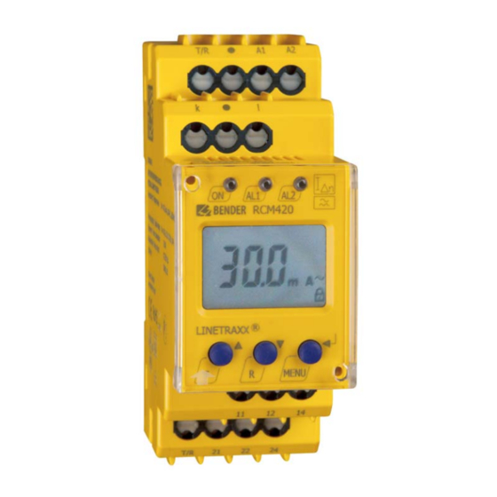
RCM420
Residual current monitor
for AC current monitoring in TN and TT systems
Software version: D240 V1.2x
RCM420_D00057_02_M_ XXEN/06.2016
Related Manuals for Bender RCM420
Summary of Contents for Bender RCM420
-
Page 1
Manual RCM420 Residual current monitor for AC current monitoring in TN and TT systems Software version: D240 V1.2x RCM420_D00057_02_M_ XXEN/06.2016… -
Page 2
Bender GmbH & Co. KG P.O. Box 1161 • 35301 Gruenberg • Germany Londorfer Strasse 65 • 35305 Gruenberg • Germany Tel.: +49 6401 807-0 • Fax: +49 6401 807-259 E-Mail: info@bender.de • www.bender.de © Bender GmbH & Co. KG All rights reserved. -
Page 3: Table Of Contents
Table of Contents 1. Important information ………………7 How to use this manual …………….. 7 Technical support: service and support ……….. 8 1.2.1 First level support ………………… 8 1.2.2 Repair service ………………… 8 1.2.3 Field service ………………….9 Training courses ………………… 10 Delivery conditions ………………
-
Page 4
Table of Contents 3.2.10 Residual current monitoring in window discriminator mode ..18 3.2.11 Password protection (on, OFF) …………..18 3.2.12 Factory setting FAC ………………18 3.2.13 Erasable history memory …………….18 3.2.14 External, combined test respectively reset button T/R ….18 3.2.15 Fault memory ……………….. -
Page 5
Table of Contents 6. Technical data ………………..39 Data in tabular form ………………39 Standards, approvals and certifications ……….42 Ordering information ………………. 43 INDEX ……………………45 RCM420_D00057_02_M_ XXEN/06.2016… -
Page 7: Important Information
1. Important information 1.1 How to use this manual This manual is intended for qualified personnel working in electrical engineering and electronics! Always keep this manual within easy reach for future reference. To make it easier for you to understand and revisit certain sections in this man- ual, we have used symbols to identify important instructions and information.
-
Page 8: Technical Support: Service And Support
Important information This manual has been compiled with great care. It might nevertheless contain errors and mistakes. Bender cannot accept any liability for injury to persons or damage to property resulting from errors or mistakes in this manual. 1.2 Technical support: service and support For commissioning and troubleshooting Bender offers you: 1.2.1…
-
Page 9: Field Service
Important information Bender GmbH, Repair-Service, Londorfer Str. 65, 35305 Grünberg 1.2.3 Field service On-site service for all Bender products Commissioning, configuring, maintenance, troubleshooting of Bender products Analysis of the electrical installation in the building (power quality test, …
-
Page 10: Training Courses
ZVEI (Zentralverband Elektrotechnik- und Elektronikindustrie e. V.) (German Electrical and Electron- ic Manufacturer’s Association) also applies. Sale and delivery conditions can be obtained from Bender in printed or elec- tronic format. 1.5 Inspection, transport and storage Inspect the dispatch and equipment packaging for damage, and compare the contents of the package with the delivery documents.
-
Page 11: Warranty And Liability
Important information 1.6 Warranty and liability Warranty and liability claims in the event of injury to persons or damage to property are excluded if they can be attributed to one or more of the follow- ing causes: Improper use of the device. …
-
Page 12: Disposal
13 August 2005 must be taken back by the manufacturer and disposed of properly. For more information on the disposal of Bender devices, refer to our homepage at www.bender-de.com -> Service & support.
-
Page 13: Safety Instructions
2. Safety instructions 2.1 General safety instructions Part of the device documentation in addition to this manual is the enclosed «Safety instructions for Bender products». 2.2 Work activities on electrical installations Only qualified personnel are permitted to carry out the work necessary to install, commission and run a device or system.
-
Page 14: Intended Use
Safety instructions 2.3 Intended use The AC and pulsed DC sensitive residual current monitor RCM420 (Type A) from Bender is designed for fault and residual current monitoring in earthed power supply systems (TN/TT systems) where an alarm is to be activated in the event of a fault, but disconnection must be prevented.
-
Page 15: Function
3. Function 3.1 Device features AC and pulsed DC sensitive residual current monitor Type A according to IEC 62020 Adjustable switching hysteresis r.m.s. value measurement Starting delay, response delay and delay on release Measured value display via multi-functional LC display …
-
Page 16: Connection Monitoring
Function function can be tested using the test button T. The parameterization of the device can be carried out via the LC display and the function keys integrated in the front plate and can be password-protected. 3.2.1 Connection monitoring The CT connections are continuously monitored. In the event of a fault, the alarm relays K1 / K2 switch without delay, the alarm LEDs AL1 / AL2 / ON flash (Error Code E.01).
-
Page 17: Functional Faults
3.2.6 Functional faults If an internal functional fault occurs, all three LEDs flash. An error code will appear on the display (E01…E32). In such a case please contact the Bender Service. 3.2.7 Set the number of reload cycles…
-
Page 18: Residual Current Monitoring In Window Discriminator Mode
Function Delay on release When no alarm exists after deactivating the fault memory, the alarm LEDs go out and the alarm relays switch back to their initial position. After activating the delay on release (0…300 s), the alarm state is continuously maintained for the selected period.
-
Page 19: Installation And Connection
4. Installation and connection Only qualified personnel are permitted to carry out the work necessary to install, commission and run a device or system. Risk of electrocution due to electric shock! Touching live parts of the system carries the risk of: An electric shock …
-
Page 20
Installation and connection The front plate cover is easy to open at the lower part marked by an arrow. 1. DIN rail mounting: Snap the rear mounting clip of the device into place in such a way that a safe and tight fit is ensured. Screw fixing: Use a tool to move the rear mounting clips (a second mounting clip required, see ordering information) to a position that it projects bey-… -
Page 21
= 100 (500 A / 5 A). That means, when the lowest value of 10 mA is set at the RCM420, a current of 1 A can only just be detected on the primary side of the transformer on the load side. In order to reduce the value that can be de- tected to 100 mA, 10 turns of the supply cable has to be routed through the transformer on the RCM side. -
Page 22
Installation and connection RCM420_D00057_02_M_ XXEN/06.2016… -
Page 23: Operation And Setting
5. Operation and setting 5.1 Display elements A detailed description of the meaning of the display elements is given in the table below. Ele- Display elements Function ment Reload function with memory = off (L = I.) Transformation ratio factor for a second external measuring current transformer.
-
Page 24: Function Of The Operating Elements
Operation and setting 5.2 Function of the operating elements Ele- Device front Function ment lights continuously: Power On LED green flashes: System fault or connection monito- ring fault AL1, LED Alarm 1 lights (yellow): Response value 1 reached Δ LED Alarm 2 lights (yellow): Res- AL1 AL2 ponse value 2 reached Δ…
-
Page 25: Menu Structure
Operation and setting 5.3 Menu structure All adjustable parameters are listed in the columns «menu item» and «adjus- table parameters». A display-like representation is used to illustrate the para- meters in the column menu item. Different alarm categories can be assigned to the alarm relays K1, K2 via the submenus r1, r2.
-
Page 26: Display In Standard Mode
Operation and setting Menu Activati Menu Adjustable parameter Menu item I 12 Selectable parameters: High, window function, low Transformation ratio factor for a second external measuring current transfor- mer. (device con- trol) Parameter setting via pass- word Re-establish factory set- tings Function blocked Display hard / software ver-…
-
Page 27: Display In Menu Mode
Operation and setting 5.5 Display in menu mode 5.5.1 Parameter query and setting: Overview Menu Adjustable parameter item Response values query and setting: – Residual current I2 (I ) (AL2) Δn2 – Residual current I1 (I ) (AL1) Δn1 – Hysteresis of the response values: % Hys Configuration of the fault memory and the alarm relays: –…
-
Page 28
Operation and setting Move to the next higher menu level (back) Menu structure RCM420_D00057_02_M_ XXEN/06.2016… -
Page 29: Changeover From Overcurrent To Undercurrent Mode Or To Window
Operation and setting Parameter settings The following description is based on the fact that the device is in the stan- dard mode and that the measured value of the residual current is being indi- cated, refer to page 26. An example is given here on how to change the alarm response value I1 (I Δn1 It is presumed that the option overcurrent (HI) has been selected in the SEt/I 12 menu (factory setting).
-
Page 30: Response Value Setting For Overcurrent
Operation and setting 5.5.3 Response value setting for overcurrent: — Response value I2 (overcurrent I Δn2 — Response value I1 (overcurrent I Δn1 — Hysteresis (Hys) of the response values I Δn1 Δn2 Increasing the response value I2 (alarm overcurrent) Increasing the response value I1 (prewarning overcurrent).
-
Page 31: Assigning Alarm Categories To The Alarm Relays
Operation and setting Setting the fault memory to con mode Setting the alarm relay K1 to N/O operation (n.o.) Setting the number of reload cycles 5.5.5 Assigning alarm categories to the alarm relays Overcurrent, undercurrent and device-related errors of the residual current monitor can be assigned to the alarm relays K1 (r1, 1) and K2 (r2, 2).
-
Page 32
Operation and setting Alarm relay K1: Deactivating the category device error Alarm relay K1: Deactivating the category response value I1 Alarm relay K1: Activating the category response value I2 RCM420_D00057_02_M_ XXEN/06.2016… -
Page 33: Set The Time Delays
Operation and setting Alarm relay K1: Deactivating the category «Alarm by device test» When an alarm relay (K1/K2) has been deactivated in the menu, an alarm will not be signalled by the respective changeover contact! An alarm will only be indicated by the CAUTION respective alarm LED (AL1/AL2)! 5.5.6…
-
Page 34: Changing From Overcurrent Operation To Window Operation
Operation and setting Setting the response delay Setting the starting delay 5.5.7 Changing from overcurrent operation to window operation Use this menu item to set whether the response values of the device apply to overcurrent (HI) or undercurrent operation (Lo). In addition, window operati- on (In) can be selected.
-
Page 35: Transformer
Operation and setting current transformer Factory setting without cascaded transformer: n = 1. 5.5.9 Factory setting and password protection Use this menu to activate the password protection, to change the password or to deactivate the password protection. In addition, you can reset the device to its factory settings.
-
Page 36: Re-Establishing The Factory Settings
Operation and setting b) Changing the password c) Deactivating the password protection 5.5.10 Re-establishing the factory settings RCM420_D00057_02_M_ XXEN/06.2016…
-
Page 37: Device Information Query
Operation and setting 5.5.11 Device information query This function is used to query the software (1.xx) versions. After activating this function, data will be displayed as a scrolling text. Once one pass is completed you can select individual data sections using the Up/Down keys. 5.5.12 History memory query The history memory can be selected via the menu HiS.
-
Page 38: Error Codes
Appropriate action when error codes > 02 occur: Carry out a reset. Reset the device to factory setting. After elimi- nating the fault, the error code will be automatically deleted. If the fault continues to exist, please contact the Bender Service. RCM420_D00057_02_M_ XXEN/06.2016…
-
Page 39: Technical Data
Technical data 6. Technical data 6.1 Data in tabular form ( )* = factory setting Insulation coordination acc. to IEC 60664-1/IEC 60664-3 RCM420-D-1: Rated insulation voltage ……………………. 100 V Overvoltage category/pollution degree………………… III/3 Rated impulse voltage ……………………2,5 kV RCM420-D-2: Rated insulation voltage ……………………
-
Page 40
……………………. 0…10 m Shielded cable ≥ 0.75 mm …………………….. 0…40 m Recommended cable (shielded, shield on one side connected to terminal l of the RCM420, not connected to earth) ………………………………..J-Y(St)Y min. 2 x 0.8 Connection …………………………screw terminals Displays, memory Display range, measured value …………………… -
Page 41
Switching elements Number of switching elements ………………… 2 x 1 changeover contact Operating principle …………….N/C operation/ N/O operation (N/O operation)* Electrical service life under rated operating conditions………… 10000 switching operations Contact data acc. to IEC 60947-5-1: Utilization category AC-13 AC-14 DC-12 DC-12… -
Page 42: Standards, Approvals And Certifications
Technical data Multi-conductor connection (2 conductors with the same cross section): rigid, flexible……………………0.2…1.5 / 0.2…1.5 mm Stripping length ……………………….8…9 mm Tightening torque ………………………. 0.5…0.6 Nm Connection type………………….push-wire terminals Connection properties: Rigid …………………….. 0.2…2.5 mm ( AWG 24…14) Flexible without ferrules ………………
-
Page 43: Ordering Information
B 9808 0603 WS80x120 80 x 120 B 9808 0606 RCM420 accessories Mounting clip for screw fixing (1 piece per device) …………….. B 9806 0008 Measuring current transformers accessories Snap-on mounting for DIN rail: W20… /W35… …………….. B 9808 0501 Snap-on mounting for DIN rail: W60 ………………….B 9808 0502…
-
Page 44
Technical data RCM420_D00057_02_M_ XXEN/06.2016… -
Page 45: Index
INDEX Adjustable parameters, list 25 Installation and connection 19 Automatic self test 16 Intended use 14 Connection of an additional cascaded K1/K2: assignment alarm category 25 measuring current transformer 21 Continuous mode (con), fault memory 18 LED Alarm 1 lights 24 LED Alarm 2 lights 24 Delay on release toff 18 Deleting the fault alarms 24…
-
Page 46
Starting delay t 17 Starting the menu mode 24 Parameter query and setting, overview 27 Support 8 Parameter setting — Activating or deactivating the pass- word protection 35 Technical data 39 — Assigning alarm categories to the Test button 24 alarm relays 31 Training courses 10 — Changing from overcurrent opera-… -
Page 48
Bender GmbH & Co. KG P.O. Box 1161 • 35301 Gruenberg • Germany Londorfer Strasse 65 • 35305 Gruenberg • Germany Tel.: +49 6401 807-0 • Fax: +49 6401 807-259 E-Mail: info@bender.de • www.bender.de Photos: Bender archives…
26
TDB401016en / Main catalogue part 4 – Residual current monitors, Residual current monitoring systems / 07.2010
4.1
Residual current monitor RCM420
Insulation coordination acc. to IEC 60664-1/IEC 60664-3
Rated insulation voltage
250 V
Rated impulse voltage/pollution degree
4 kV / III
Protective separation (reinforced insulation) between
(A1, A2) — (k, l, T/R) — (11, 12, 14) — (21, 22, 24)
Voltage tests according to IEC 61010-1
2.21 kV
Supply voltage
RCM420-D-1:
Supply voltage U
S
AC 16…72 V / DC 9.6…94 V
Frequency range U
S
42…460 Hz
RCM420-D-2:
Supply voltage U
S
AC/DC 70…300 V
Frequency range U
S
42…460 Hz
Power consumption
≤ 3 VA
Measuring circuit
Measuring current transformers, external type
W…, WR…, WS…
Load 68
Ω
Rated insulation voltage (measuring current transformer)
800 V
Operating characteristic acc. to IEC 62020 and IEC/TR 60755
Type A
Rated frequency
42…2000 Hz
Measuring range
3 mA…16 A
Relative uncertainty
0…-20%
Relative uncertainty
0…30%
Response values
Rated residual operating current I
Δn1
(prewarning, AL1)
50…100 % x I
Δn2
, (50 %)*
Rated residual operating current I
Δn2
(alarm, AL2)
10 mA…10 A (30 mA)*
Hysteresis
10…25 % (15%)*
Specified time
Start-up delay t
0…10 s (0.5 s)*
Response delay t
on2
(alarm)
0…10 s (0 s)*
Response delay t
on1
(prewarning)
0…10 s (1 s)*
Delay on release t
off
0…99 s (1 s)*
Operating time t
ae
at I
Δn
= 1 x I
Δn1/2
≤ 180 ms
Operating time t
ae
at I
Δn
= 5 x I
Δn1/2
≤ 30 ms
Response time t
an
t
an
= t
ae
+ t
on1/2
Recovery time t
b
≤ 300 ms
Number of restart cycles
0…100 (0)*
Cable lengths for measuring current transformers
Single wire ≥ 0.75 mm²
0…1 m
Single wire, twisted ≥ 0.75 mm²
0…10 m
Shielded cable ≥ 0.75 mm²
0…40 m
Recommended cable
(shielded, shield on one side connected to terminal l of the RCM420, not connected to earth)
J-Y(St)Y min. 2×0.8
Connection screw-type
terminals
Displays, memory
Display range, measuring value
3 mA…16 A
Error of indication
±15 % / ± 2 digit
Measured-value memory for alarm value
data record measured values
Password
off / 0…999 (off)*
Fault memory alarm relay
on / off (on)*
Inputs/outputs
Cable length for external test/reset button
0…10 m
Switching elements
Number of switching elements
2 x 1 changeover contact
Operating principle
N/C operation / N/O operation (N/C operation)*
Electrical endurance, number of cycles
10000
Contact data acc. to IEC 60947-5-1:
Utilisation category
AC-13 AC-14 DC-12 DC-12 DC-12
Rated operational voltage
230 V 230 V
24 V 110 V 220 V
Rated operational current
5 A
3 A
1 A
0.2 A
0.1 A
Minimum contact rating
1 mA at AC/DC ≥ 10 V
Environment/EMC
EMC
IEC 62020: 2005-11
Operating temperature
-25 ºC…+55 ºC
Climatic class acc. to IEC 60721
Stationary use (IEC 60721-3-3)
3K5 (except condensation and formation of ice)
Transport (IEC 60721-3-2)
2K3 (except condensation and formation of ice)
Long-time storage (IEC 60721-3-1)
1K4 (except condensation and formation of ice)
Classification of mechanical conditions IEC 60721
Stationary use (IEC 60721-3-3)
3M4
Transport (IEC 60721-3-2)
2M2
Long-time storage (IEC 60721-3-1)
1M3
Connection
Connection type
push-wire terminals
Connection properties
rigid
0.2…2.5 mm² / AWG 24-12
flexible without ferrule
0.2…2.5 mm² / AWG 24-12
flexible with ferrule
0.2…1.5 mm² / AWG 24-16
Stripping length
10 mm
Opening force
50 N
Test opening, diameter
2.1 mm
Other
Operating mode
continuous operation
Position of normal use
any
Degree of protection, internal components (IEC 60529)
IP30
Degree of protection, terminals (IEC 60529)
IP20
Enclosure material
polycarbonate
Flammability class
UL94V-0
DIN rail mounting acc. to
IEC 60715
Screw fixing
2 x M4 with mounting clip
Operating manual
TGH1410
Weight
≤ 150 g
( )* = factory setting
Technical data
Ordering information
Type
Response range I
Δn
Frequency range
Measuring current transformers
Supply voltage U
S
*
Art. No.
RCM420-D-1
10 mA…10 A
42…2000 Hz
W…, WR…, WS…
DC 9.6…94 V / AC 42…460 Hz 16…72 V
B 7401 4001
RCM420-D-2
10 mA…10 A
42…2000 Hz
W…, WR…, WS…
DC 70…300 V / AC 42…460 Hz 70…300 V
B 7401 4002
Device version with screw terminals on request.
* Absolute values
- Manuals
- Brands
- Bender Manuals
- Monitor
- RCM420 Series
- Manual
Residual current monitor
Hide thumbs
Also See for RCM420:
- Operating manual (44 pages)
- Manual (48 pages)
- Technical bulletin (6 pages)
,
,
1
2
Table Of Contents
3
4
5
6
7
8
9
10
11
12
13
14
15
16
17
18
19
20
21
22
23
24
25
26
27
28
29
30
31
32
33
34
35
36
37
38
39
40
41
42
43
44
45
46
47
48
49
50
51
52
-
page
of
52/
52 -
Contents
-
Table of Contents
-
Bookmarks
Table of Contents
Advertisement
Bender GmbH & Co. KG
PO Box 1161 • 35301 Gruenberg • Germany
Londorfer Strasse 65 • 35305 Gruenberg • Germany
Tel.: +49 6401 807-0 • Fax: +49 6401 807-259
E-Mail: info@bender.de • www.bender.de
©
Bender GmbH & Co. KG
All rights reserved.
Reprinting only with permission of the publisher.
Subject to change!
Photos: Bender archives
Table of Contents
Previous Page
Next Page
- 1
- 2
- 3
- 4
- 5
- 6
Advertisement
Table of Contents
Related Manuals for Bender RCM420
-

Measuring Instruments Bender RCM420 Manual
Residual current monitor (48 pages)
-
Monitor Bender rcm420 Operating Manual
Residual current monitor for ac current monitoring in tn and tt systems (44 pages)
-
Monitor Bender RCM420 Series Technical Bulletin
Digital ground fault monitor / ground fault relay
grounded and high-resistance grounded ac systems (6 pages) -
Monitor Bender RCMA420 Operating Manual
Residual current monitor for monitoring ac, dc and pulsed dc currents in tn and tt systems (40 pages)
-
Monitor Bender RCMS460 Manual
Residual current monitors (104 pages)
-
Monitor Bender RCMA423-DM Manual
Residual current monitor (52 pages)
-
Monitor Bender LINETRAXX RCMS150 Series Manual
Residual current monitor type b with integrated measuring current transformers for earthed ac/dc systems (tn and tt systems) (52 pages)
-
Monitor Bender RCMA474 Manual
Ac/dc sensitive residual current monitor (8 pages)


-
Monitor Bender RCMA426H-DCB Manual
Residual current monitor for monitoring ac, dc and pulsed dc currents in earthed and resistance earthed systems (40 pages)
-
Monitor Bender LINETRAXX RCMS460-D Quick Start Manual
Multi-channel residual current monitors for earthed ac, dc and ac/dc systems (tn and tt) ac, pulsed dc and ac/dc sensitive (8 pages)
-
Monitor Bender COMTRAXX CP700 Manual
Condition monitor for the connection of bender bms devices and universal measuring devices to tcp/ip networks (172 pages)
-
Monitor Bender COMTRAXX CP700 Quick Start Manual
Condition monitor for bender bms devices and universal measuring devices (8 pages)
-
Monitor Bender VMD420 Manual
Voltage and frequency monitor (40 pages)
-
Monitor Bender VMD421H Manual
Voltage and frequency monitor for undervoltage, overvoltage, underfrequency and overfrequency monitoring in 3 n ac systems of 70…500 v, software version d239 v2.2x (60 pages)
-
Monitor Bender FP200 Quick Start Manual
Front panel for isometer® iso685-s variants (12 pages)
-
Monitor Bender VMD421H Operating Manual
Voltage and frequency monitor for undervoltage, overvoltage, underfrequency and overfrequency monitoring in 3(n)ac systems of 70…500 v (48 pages)


Related Products for Bender RCM420
- Bender RCMA420
- Bender RCMS460
- Bender RCMS490
- Bender RCMA423-DM
- Bender RCMA426H-DCB
- Bender LINETRAXX RCM410R-1
- Bender LINETRAXX RCM410R-2
- Bender RCMA421H-D2
- Bender RCMB300 Series
- Bender RCMB301
- Bender RCMA423AS
- Bender RCMB102
- Bender RCMB330
- Bender RCMA423
- Bender RCMB103
- Bender RCMB104
Manual, Technical Bulletin for Bender RCM420 Series Measuring Instruments, Monitor (6 pages)
Specifications:1290/1290379-rcm420_series.pdf file (11 Jun 2023) |
Accompanying Data:
Bender RCM420 Series Measuring Instruments, Monitor PDF Technical Bulletin (Updated: Sunday 11th of June 2023 05:44:11 PM)
Rating: 4.5 (rated by 62 users)
Compatible devices: RCMA423AS, EDS3090, ISOMETER IRDH275BM-7, iso1685 Series, RCMA420, FP200, RCMA423, CMD420.
Recommended Documentation:
Text Version of Manual, Technical Bulletin
(Ocr-Read Summary of Contents of some pages of the Bender RCM420 Series Document (Main Content), UPD: 11 June 2023)
-
1, Bender RCM420 Series RCM420 Series Digital Ground Fault Monitor / Ground Fault Relay Grounded and High-Resistance Grounded AC Systems T M 4 Technical Bulletin NAE1042031 / 08.2013
… -
2, 2 RCM420 Series Digital Ground Fault Monitor / Relay for Grounded AC Systems RCM420 Features • Ground fault monitoring for AC grounded systems • True RMS value measurement (AC) • External measuring current transformer • Two separately adjustable response values • Frequency range 42 — 2000 Hz…
-
3, 3 Operating and display elements 1 — Power “ON” LED (green): Illuminates when power is received to the unit. Flashes when the current transformer connection alarm is active. 2 — Alarm LED “AL1” (yellow): Alarm 1, illuminates when the set res ponse value I Δn1 has been exceeded. Flashes when the cur…
-
4, Bender RCM420 Series 4 Ground Fault Monitor RCM420 Insulation coordination acc. to IEC 60664-1 / IEC 60664-3 Rated insulation voltage 250 V Rated impulse voltage / pollution degree 2.5 kV / III Protective separation (reinforced insulation) between (A1, A2) — (k / l, T / R) – (11, 12, 14) – (21, 22, 24) Voltage test a…
-
5, 5 Dimensions Dimensions in inches (mm) 1.42” (36) 2.78” (70.5) 1.87” (47.5) 1.22” (31.1) 2.66” (67.5) 1.77” (45) 3.54” (90) Supply voltage 1) U S Outputs Type Ordering No. DC AC 9.6 — 94 V 16 — 72 V (15 — 460 Hz) 2 SPDT contacts RCM420-D-1 B 9401 4001 70 — 300 V 70 — 300 V (15 — 460 H…
-
6, Document NAE1042031 / 08.2013 / © Bender Inc. T M Canada • Mississauga, ON Toll-Free: 800-243-2438 • Main: 905-602-9990 Fax: 905-602-9960 • E-mail: [email protected] USA • Coatesville, PA Toll-Free: 800-356-4266 • Main: 610-383-9200 Fax: 610-383-7100 • E-mail: [email protected] bender.org • …
-
Bender RCM420 Series User Manual
-
Bender RCM420 Series User Guide
-
Bender RCM420 Series PDF Manual
-
Bender RCM420 Series Owner’s Manuals
Recommended: MDR-XB1000, 560689, Total Control


-
Advan AMM240WTD
AUTO — SCANNING WITH DIGITAL CONTROLLCD COLOR MEDICAL MONITORAMM240WTDOperation ManualFor future reference, record the serial number of your displaymonitor in the space below :Serial NumberThe serial number is located on the back of the monitor …
AMM240WTD 37
-
NEC MultiSync LCD400V LA-1422JMW LA-1422JMW
MultiSync®LCD400V™User’s ManualContents 1Quick Start 2-3Controls 4-5Recommended Use 6-7Specifications 8Features 9Troubleshooting 10References 11Limited Warranty 12MultiSync®LCD400V™User’s Manual78133331 9/25/98, 12:46 PM1 …
MultiSync LCD400V LA-1422JMW LA-1422JMW 15
-
Unytouch U09-T150
“artistry in technology”21 0 1 0 1 0 1 0 1 0 1 0 1 0 1 0 1 0 1 0 1 0 1 01 0 1 0 1 0 1 0 1 0 1 0 1 0 1 0 1 0 1 0 1 0 1 01 0 1 0 1 0 1 0 1 0 1 0 1 0 1 0 1 0 1 0 …
U09-T150 1
-
LG L1753PL1953P
Make sure to read the Important Precautions before using the product. Keep the User’s Guide(CD) in an accessible place for furture reference.See the label attached on the product and give the information to yourdealer when you ask for service.L1753PL1953PL1753PRL1953PRL1753PML1953PMUser’s Gui …
L1753PL1953P 28
Additional Information:
Popular Right Now:
Operating Impressions, Questions and Answers:

EN Manual RCM420 Residual current monitor for AC current monitoring in TN and TT systems Software version: D240 V1.2x RCM420_D00057_02_M_ XXEN/06.2016 Bender GmbH & Co. KG P.O. Box 1161 • 35301 Gruenberg • Germany Londorfer Strasse 65 • 35305 Gruenberg • Germany Tel.: +49 6401 807-0 • Fax: +49 6401 807-259 E-Mail: [email protected] • www.bender.de © Bender GmbH & Co. KG All rights reserved. Reprinting only with permission of the publisher. Subject to change! Photos: Bender archives Table of Contents 1. Important information .................................................................................... 7 1.1 1.2 1.2.1 1.2.2 1.2.3 1.3 1.4 1.5 1.6 1.7 How to use this manual ................................................................................. 7 Technical support: service and support ................................................... 8 First level support ............................................................................................. 8 Repair service ..................................................................................................... 8 Field service ........................................................................................................ 9 Training courses ............................................................................................. 10 Delivery conditions ....................................................................................... 10 Inspection, transport and storage ........................................................... 10 Warranty and liability ................................................................................... 11 Disposal ............................................................................................................ 12 2. Safety instructions ......................................................................................... 13 2.1 2.2 2.3 General safety instructions ........................................................................ 13 Work activities on electrical installations ............................................. 13 Intended use ................................................................................................... 14 3. Function ........................................................................................................... 15 3.1 3.2 3.2.1 3.2.2 3.2.3 3.2.4 3.2.5 3.2.6 3.2.7 3.2.8 3.2.9 Device features .............................................................................................. Function ............................................................................................................ Connection monitoring .............................................................................. Additional cascaded measuring current transformer ...................... Fast response value query ......................................................................... Automatic self test ........................................................................................ Manual self test .............................................................................................. Functional faults ............................................................................................ Set the number of reload cycles .............................................................. Assigning alarm categories to alarm relays K1/K2 ............................ Time delays t, ton and toff ....................................................................... RCM420_D00057_02_M_ XXEN/06.2016 15 15 16 16 16 16 16 17 17 17 17 3 Table of Contents 3.2.10 3.2.11 3.2.12 3.2.13 3.2.14 3.2.15 Residual current monitoring in window discriminator mode ...... 18 Password protection (on, OFF) ................................................................. 18 Factory setting FAC ...................................................................................... 18 Erasable history memory ............................................................................ 18 External, combined test respectively reset button T/R ................... 18 Fault memory .................................................................................................. 18 4. Installation and connection ......................................................................... 19 5. Operation and setting .................................................................................. 23 5.1 5.2 5.3 5.4 5.5 5.5.1 5.5.2 5.5.3 5.5.4 5.5.5 5.5.6 5.5.7 5.5.8 5.5.9 5.5.10 5.5.11 5.5.12 5.6 5.7 5.8 4 Display elements ........................................................................................... 23 Function of the operating elements ...................................................... 24 Menu structure ............................................................................................... 25 Display in standard mode .......................................................................... 26 Display in menu mode ................................................................................ 27 Parameter query and setting: Overview ............................................... 27 Changeover from overcurrent to undercurrent mode or to window mode .................................................................................................................. 29 Response value setting for overcurrent: ............................................... 30 Setting the fault memory and alarm relay operating mode .......... 30 Assigning alarm categories to the alarm relays ................................. 31 Set the time delays ....................................................................................... 33 Changing from overcurrent operation to window operation ...... 34 Setting the correction factor for an additional cascaded current transformer ...................................................................................................... 34 Factory setting and password protection ............................................ 35 Re-establishing the factory settings ....................................................... 36 Device information query .......................................................................... 37 History memory query ................................................................................. 37 Commissioning .............................................................................................. 37 Factory setting ............................................................................................... 37 Error codes ....................................................................................................... 38 RCM420_D00057_02_M_ XXEN/06.2016 Table of Contents 6. Technical data ................................................................................................ 39 6.1 6.2 6.3 Data in tabular form ..................................................................................... 39 Standards, approvals and certifications ................................................ 42 Ordering information ................................................................................... 43 INDEX .................................................................................................................... 45 5 RCM420_D00057_02_M_ XXEN/06.2016 1. Important information 1.1 How to use this manual This manual is intended for qualified personnel working in electrical engineering and electronics! Always keep this manual within easy reach for future reference. To make it easier for you to understand and revisit certain sections in this manual, we have used symbols to identify important instructions and information. The meaning of these symbols is explained below: DANGER This signal word indicates that there is a high risk of danger that will result in electrocution or serious injury if not avoided. This signal word indicates a medium risk of danger that can lead to death or serious injury if not avoided. WARNING CAUTION This signal word indicates a low level risk that can result in minor or moderate injury or damage to property if not avoided. This symbol denotes information intended to assist the user in making optimum use of the product. RCM420_D00057_02_M_ XXEN/06.2016 7 Important information This manual has been compiled with great care. It might nevertheless contain errors and mistakes. Bender cannot accept any liability for injury to persons or damage to property resulting from errors or mistakes in this manual. 1.2 Technical support: service and support For commissioning and troubleshooting Bender offers you: 1.2.1 First level support Technical support by phone or e-mail for all Bender products Questions concerning specific customer applications Commissioning Troubleshooting Telephone: Fax: In Germany only: E-mail: 1.2.2 +49 6401 807-760* +49 6401 807-259 0700BenderHelp (Tel. and Fax) [email protected] Repair service Repair, calibration, update and replacement service for Bender products Repairing, calibrating, testing and analysing Bender products Hardware and software update for Bender devices Delivery of replacement devices in the event of faulty or incorrectly delivered Bender devices Extended guarantee for Bender devices, which includes an in-house repair service or replacement devices at no extra cost Telephone: Fax: E-mail: +49 6401 807-780** (technical issues) +49 6401 807-784**, -785** (sales) +49 6401 807-789 [email protected] Please send the devices for repair to the following address: 8 RCM420_D00057_02_M_ XXEN/06.2016 Important information Bender GmbH, Repair-Service, Londorfer Str. 65, 35305 Grünberg 1.2.3 Field service On-site service for all Bender products Commissioning, configuring, maintenance, troubleshooting of Bender products Analysis of the electrical installation in the building (power quality test, EMC test, thermography) Training courses for customers Telephone: Fax: E-mail: Internet: +49 6401 807-752**, -762 **(technical issues) +49 6401 807-753** (sales) +49 6401 807-759 [email protected] www.bender-de.com *Available from 7.00 a.m. to 8.00 p.m. 365 days a year (CET/UTC+1) **Mo-Thu 7.00 a.m. - 8.00 p.m., Fr 7.00 a.m. - 13.00 p.m RCM420_D00057_02_M_ XXEN/06.2016 9 Important information 1.3 Training courses Bender is happy to provide training regarding the use of test equipment. The dates of training courses and workshops can be found on the Internet at www.bender-de.com -> Know-how -> Seminars. 1.4 Delivery conditions Bender sale and delivery conditions apply. For software products the "Softwareklausel zur Überlassung von StandardSoftware als Teil von Lieferungen, Ergänzung und Änderung der Allgemeinen Lieferbedingungen für Erzeugnisse und Leistungen der Elektroindustrie" (software clause in respect of the licensing of standard software as part of deliveries, modifications and changes to general delivery conditions for products and services in the electrical industry) set out by the ZVEI (Zentralverband Elektrotechnik- und Elektronikindustrie e. V.) (German Electrical and Electronic Manufacturer's Association) also applies. Sale and delivery conditions can be obtained from Bender in printed or electronic format. 1.5 Inspection, transport and storage Inspect the dispatch and equipment packaging for damage, and compare the contents of the package with the delivery documents. In the event of damage in transit, please contact Bender immediately. The devices must only be stored in areas where they are protected from dust, damp, and spray and dripping water, and in which the specified storage temperatures can be ensured. 10 RCM420_D00057_02_M_ XXEN/06.2016 Important information 1.6 Warranty and liability Warranty and liability claims in the event of injury to persons or damage to property are excluded if they can be attributed to one or more of the following causes: Improper use of the device. Incorrect mounting, commissioning, operation and maintenance of the device. Failure to observe the instructions in this operating manual regarding transport, commissioning, operation and maintenance of the device. Unauthorised changes to the device made by parties other than the manufacturer. Non-observance of technical data. Repairs carried out incorrectly and the use of replacement parts or accessories not approved by the manufacturer. Catastrophes caused by external influences and force majeure. Mounting and installation with device combinations not recommended by the manufacturer. This operating manual, especially the safety instructions, must be observed by all personnel working on the device. Furthermore, the rules and regulations that apply for accident prevention at the place of use must be observed. RCM420_D00057_02_M_ XXEN/06.2016 11 Important information 1.7 Disposal Abide by the national regulations and laws governing the disposal of this device. Ask your supplier if you are not sure how to dispose of the old equipment. The directive on waste electrical and electronic equipment (WEEE directive) and the directive on the restriction of certain hazardous substances in electrical and electronic equipment (RoHS directive) apply in the European Community. In Germany, these policies are implemented through the "Electrical and Electronic Equipment Act" (ElektroG). According to this, the following applies: Electrical and electronic equipment are not part of household waste. Batteries and accumulators are not part of household waste and must be disposed of in accordance with the regulations. Old electrical and electronic equipment from users other than private households which was introduced to the market after 13 August 2005 must be taken back by the manufacturer and disposed of properly. For more information on the disposal of Bender devices, refer to our homepage at www.bender-de.com -> Service & support. 12 RCM420_D00057_02_M_ XXEN/06.2016 2. Safety instructions 2.1 General safety instructions Part of the device documentation in addition to this manual is the enclosed "Safety instructions for Bender products". 2.2 Work activities on electrical installations Only qualified personnel are permitted to carry out the work necessary to install, commission and run a device or system. DANGER Risk of electrocution due to electric shock! Touching live parts of the system carries the risk of: An electric shock Damage to the electrical installation Destruction of the device Before installing and connecting the device, make sure that the installation has been de-energised. Observe the rules for working on electrical installations. If the device is used outside the Federal Republic of Germany, the applicable local standards and regulations must be complied with. The European standard EN 50110 can be used as a guide. RCM420_D00057_02_M_ XXEN/06.2016 13 Safety instructions 2.3 Intended use The AC and pulsed DC sensitive residual current monitor RCM420 (Type A) from Bender is designed for fault and residual current monitoring in earthed power supply systems (TN/TT systems) where an alarm is to be activated in the event of a fault, but disconnection must be prevented. In addition, the device can be used to monitor single conductors, such as PE conductors, N-PE connections and PE-PAS connections. Two separately adjustable response ranges IΔn1 and IΔn2 allow to distinguish between prewarning and alarm (IΔn1 = 50…100 % of the set response value IΔn2). In order to meet the requirements of the applicable standards, customised parameter settings must be made on the equipment in order to adapt it to local equipment and operating conditions. Please heed the limits of the range of application indicated in the technical data. Any use other than that described in this manual is regarded as improper. 14 RCM420_D00057_02_M_ XXEN/06.2016 3. Function 3.1 Device features AC and pulsed DC sensitive residual current monitor Type A according to IEC 62020 Adjustable switching hysteresis r.m.s. value measurement Starting delay, response delay and delay on release Measured value display via multi-functional LC display Alarm indication via LEDs (AL1, AL2) and changeover contacts (K1, K2) N/C operation or N/O operation selectable Password protection against unauthorized parameter changing Fault memory function can be switched off CT connection monitoring 3.2 Function Once the supply voltage Us is applied, the starting delay "t" is activated. Measured values exceeded during this time do not influence the switching state of the alarm relays. Residual current monitoring takes place via an external measuring current transformer. The currently measured value is shown on the LC display. In this way any changes can be recognized easily, for example, when circuits are connected to the system. If the measured value exceeds one or both response values, the response delay ton1/2 starts running. After the expiry of the response delay ton1/2, the selected alarm relay switches and the alarm LEDs light. If the release value is not reached before the expiry of ton, no alarm will be signalled: the LEDs AL1, AL2 do not light and the alarm relays do not switch. The set release time toff begins when the measured value again falls below the release value (response value plus hysteresis) after the switching of the alarm relays. After the expiry of toff, the alarm relays switch back to their initial position. With the fault memory activated, the alarm relays do not change their actual state until the reset button R is pressed. The device RCM420_D00057_02_M_ XXEN/06.2016 15 Function function can be tested using the test button T. The parameterization of the device can be carried out via the LC display and the function keys integrated in the front plate and can be password-protected. 3.2.1 Connection monitoring The CT connections are continuously monitored. In the event of a fault, the alarm relays K1 / K2 switch without delay, the alarm LEDs AL1 / AL2 / ON flash (Error Code E.01). After eliminating the fault, the alarm relays automatically return to their initial position, provided that the fault memory M is deactivated. With the fault memory activated, K1/K2 return to their initial position by pressing the reset button R. A second cascaded measuring current transformer will not be monitored. 3.2.2 Additional cascaded measuring current transformer For applications where residual currents higher than 10 A occur, a second external transformer can be cascaded. The transformer's transmission ratio can be adapted using the correction factor nRCM in the SEt menu. Refer to page 21 and page 34. 3.2.3 Fast response value query With the display in standard mode, the currently measured response values IΔn1 and IΔn2 can be queried pressing the Up and Down keys ( < 1.5 s). Switchover to the Menu mode is not required. If you want to exit the fast response value query, press the enter key. 3.2.4 Automatic self test The device automatically carries out a self test after connecting to the system to be monitored and later every 24 hours. During the self test internal functional faults will be detected and appear in form of an error code on the display. The alarm relays are not checked during this test. 3.2.5 Manual self test After pressing the test button for > 1.5 s, the device carries out a self test. During this test, internal functional faults are detected and will be displayed in form of an error code. The alarm relays are not checked during this test. 16 RCM420_D00057_02_M_ XXEN/06.2016 Function While the test button T is pressed and held down, all device-related display elements appear on the display. 3.2.6 Functional faults If an internal functional fault occurs, all three LEDs flash. An error code will appear on the display (E01…E32). In such a case please contact the Bender Service. 3.2.7 Set the number of reload cycles If faults occur only temporarily, but recurrently, in the system being monitored, with the fault memory M deactivated, the alarm relays would switch synchronously to the error status. RL in the out menu can be used to limit the number of these changeover processes. As soon as the preset number of switching cycles is exceeded, the fault memory will come on and an activated alarm remains stored. 3.2.8 Assigning alarm categories to alarm relays K1/K2 The alarm categories device error, residual current IΔn1, residual current IΔn2 or device test can be assigned to the alarm relay via the "out" menu. 3.2.9 Time delays t, ton and toff The times t, ton and toff, described below, delay the output of alarms via LEDs and relays. Starting delay t After connection to the supply voltage US, the alarm indication is delayed by the preset time t (0…10 s). Response delay ton1/2 If the response value is exceeded or not reached, the residual current monitor requires the response time tan. After the expiry of the response time an alarm is signalled. A set response delay ton1/2 (0…10 s) adds up to the device-related operating time tae and delays alarm signalling (total delay time tan = tae + ton). If the residual current fault changes from a value above the response value to a value below the response value, an alarm will not be signalled. RCM420_D00057_02_M_ XXEN/06.2016 17 Function Delay on release toff When no alarm exists after deactivating the fault memory, the alarm LEDs go out and the alarm relays switch back to their initial position. After activating the delay on release (0…300 s), the alarm state is continuously maintained for the selected period. 3.2.10 Residual current monitoring in window discriminator mode Change the measuring principle by selecting the window mode (SEt / In). In the window discriminator mode, the threshold values I1 and I2 represent the upper and the lower value. If the measured value is not within this area, an alarm is initiated by the device. See page 34. 3.2.11 Password protection (on, OFF) When the password protection is activated (on), settings are only possible after entering the correct password (0…999). 3.2.12 Factory setting FAC After activating the factory setting, all settings previously changed are reset to delivery status. 3.2.13 Erasable history memory The first alarm value that occurs will be saved in this memory. The memory can be cleared via the menu HiS. 3.2.14 External, combined test respectively reset button T/R Reset = Pressing the external button < 1.5 s Test = Pressing the external button > 1.5 s 3.2.15 Fault memory The fault memory can be activated, deactivated or set to continuous mode (con). If the fault memory is set to "con" mode, the alarm parameters remain stored even on failure of the supply voltage. Stored alarms can be reset by means of the reset button R. 18 RCM420_D00057_02_M_ XXEN/06.2016 4. Installation and connection Only qualified personnel are permitted to carry out the work necessary to install, commission and run a device or system. DANGER Risk of electrocution due to electric shock! Touching live parts of the system carries the risk of: An electric shock Damage to the electrical installation Destruction of the device Before installing and connecting the device, make sure that the installation has been de-energised. Observe the rules for working on electrical installations. Dimension diagram, drawing for screw mounting, push-wire terminal connection Zubehör/ Accessory 36 mm 45 116 mm 67,5 RCM420_D00057_02_M_ XXEN/06.2016 100 mm 2 90 mm ,5 70 ,5 47 ,1 31 1 3 19 Installation and connection The front plate cover is easy to open at the lower part marked by an arrow. 1. DIN rail mounting: Snap the rear mounting clip of the device into place in such a way that a safe and tight fit is ensured. Screw fixing: Use a tool to move the rear mounting clips (a second mounting clip required, see ordering information) to a position that it projects beyond the enclosure. Then fix the device using two M4 screws. 2. Wiring Connect the device according the wiring diagram. T/R A1 A2 k l 11 12 14 Load T/R 21 22 24 Terminal Connections A1, A2 Connection to supply voltage Us k, l Connection of measuring current transformers T / R Connection to the combined test and reset button 11, 12, 14 Alarm relay K1 21, 22, 24 Alarm relay K2 20 RCM420_D00057_02_M_ XXEN/06.2016 Installation and connection Connection of an additional cascaded measuring current transformer If the residual current range of 10 A is not sufficient, an additional measuring current transformer can be cascaded. Connect the measuring current transformer as illustrated in the drawing below. X1 nRCM = X2 RCM420 X2 X1 (x A/10 A) (x A/5 A) (x A/1 A) BENDER W..., WR..., WS... Load Example: An additionally cascaded transformer on the load side has a transmission ratio of X1 = 100 (500 A / 5 A). That means, when the lowest value of 10 mA is set at the RCM420, a current of 1 A can only just be detected on the primary side of the transformer on the load side. In order to reduce the value that can be detected to 100 mA, 10 turns of the supply cable has to be routed through the transformer on the RCM side. Hence, the correction factor to be set is nRCM = X1:X2 = 100:10 = 10. The correction factor can be set via the SEt/n menu. Refer to page 34. The correction factor is factory set to 1 and relates to normal operation with one Bender measuring current transformer only (X = 600:1). RCM420_D00057_02_M_ XXEN/06.2016 21 Installation and connection 22 RCM420_D00057_02_M_ XXEN/06.2016 5. Operation and setting 5.1 Display elements A detailed description of the meaning of the display elements is given in the table below. Display elements Element RL n I2 I1 r1, 1 r2, 2 Function Reload function with memory = off (L = I.) Transformation ratio factor for a second external measuring current transformer. Response value IΔn2 as mA (Alarm 2) Response value IΔn1 as % of IΔn2 (Alarm 1, prewarning.) Alarm relay K1 Alarm relay K2 I Hys, % Response value hysteresis as %. ton1, ton2, t, toff Response delay ton1 (K1) Response delay ton2 (K2) Starting delay t, Delay on release toff for K2 M fault memory active Relay operating mode K2 Password protection enabled RCM420_D00057_02_M_ XXEN/06.2016 23 Operation and setting 5.2 Function of the operating elements Device front ON T 24 AL1 AL2 R MENU Element Function ON, lights continuously: Power On LED green flashes: System fault or connection monitoring fault AL1, LED Alarm 1 lights (yellow): Response value 1 reached (IΔn1) AL2 LED Alarm 2 lights (yellow): Response value 2 reached (IΔn2) 13 mA 13 mA flow through the measuring current transformer, fault memory active M T, Test button (> 1.5 s): To indicate the available display elements, to start a self test; Up key (< 1.5 s): Menu items/values R, Reset button (> 1.5 s): Deleting the fault memory; Down key (< 1.5 s): Menu items/values MENU, MENU key (> 1.5 s): Starting the menu mode; Enter key (< 1.5 s): Confirm menu item, submenu item and value. Enter key (> 1.5 s): Back to the next higher menu level. RCM420_D00057_02_M_ XXEN/06.2016 Operation and setting 5.3 Menu structure All adjustable parameters are listed in the columns "menu item" and "adjustable parameters". A display-like representation is used to illustrate the parameters in the column menu item. Different alarm categories can be assigned to the alarm relays K1, K2 via the submenus r1, r2. This is done by activation or deactivation of the respective function. Menu Sub Menu AL (response values) out r1 (output con- (K1: (assignment alarm trol) category) r2 (K2: (assignment alarm category) t (timing check) Menu item Activati on > I2 - (HI) IΔn2 (Alarm 2) > I1 - (HI) Hys - IΔn1 as % of IΔn2 (Alarm 1, prewarning) Hysteresis IΔn1 / IΔn2 M 1 ON - Fault memory Operating mode K1 (n.c.) 2 - Operating mode K2 (n.c.) RL - 1 Err r1 I1 ON ON Reload function (memory = off ) Device error at K1 Prewarning IΔn1 at K1 r1 I2 off Alarm IΔn2 at K1 1 tES 2 Err r2 I1 ON ON off Device test Device error at K2 Prewarning IΔn1 at K2 r2 I2 ON Alarm IΔn2 at K2 2 tES t on 1 t on 2 t t off ON - Device test Response delay K1 Response delay K2 Starting delay Delay on release K1/K2 RCM420_D00057_02_M_ XXEN/06.2016 Adjustable parameter 25 Operation and setting Menu Sub Menu Menu item Activati on I 12 HI n 1 Set (device control) off FAC - SYS - Clr - InF HiS Adjustable parameter Selectable parameters: High, window function, low Transformation ratio factor for a second external measuring current transformer. Parameter setting via password Re-establish factory settings Function blocked Display hard / software version History memory for the first alarm value, erasable 5.4 Display in standard mode By default, the currently measured residual current is displayed. The current response values I1 (prewarning) and I2 (alarm) can be displayed using the Up and Down key. Press the Enter key to return to the measured value. In the standard mode, the currently set response values I 1 and I 2 can be displayed using the Up and Down keys. 26 RCM420_D00057_02_M_ XXEN/06.2016 Operation and setting 5.5 Display in menu mode 5.5.1 Menu item Parameter query and setting: Overview Adjustable parameter InF Response values query and setting: – Residual current I2 (IΔn2) (AL2) – Residual current I1 (IΔn1) (AL1) – Hysteresis of the response values: % Hys Configuration of the fault memory and the alarm relays: – Activating/deactivating the fault memory or assign continuous mode (on/off/con) – Select N/O operation (n.o.) or N/C operation (n.c.) individually for each K1/K2 – Specify the number of the reload cycles – Assign the alarm category I1 (IΔn1) or I2 (IΔn2), relay test or device error individually to K1/K2 (1, r1/ 2, r2). Set delays: – Response delay ton1/ton2 – Starting delay t – Delay on release toff (LED, relay) Device control parameter setting: – Select the appropriate parameter for response values: overcurrent mode (HI), undercurrent mode (Lo) or window mode (In). – Set the correction factor nRCM (n) for additional cascaded current transformer. – Enable or disable password protection, change the password. – Re-establish factory settings. – Service menu SyS blocked Query hard and software version HiS Query the first stored alarm value. AL out t SEt RCM420_D00057_02_M_ XXEN/06.2016 27 Operation and setting ESC Move to the next higher menu level (back) Menu structure t >1,5 s t > 1,5 s t < 1,5 s AL out t SEt InF HiS ESC t < 1,5 s t > 1,5 s ESC 28 RCM420_D00057_02_M_ XXEN/06.2016 Operation and setting Parameter settings The following description is based on the fact that the device is in the standard mode and that the measured value of the residual current is being indicated, refer to page 26. An example is given here on how to change the alarm response value I1 (IΔn1). It is presumed that the option overcurrent (HI) has been selected in the SEt/I 12 menu (factory setting). Proceed as follows: 1. To access the menu mode, press the MENU/Enter key for more than 1.5 seconds. The flashing short symbol AL appears on the display. 2. Confirm with Enter. The parameter response value > I 2 flashes, in addition the associated overcurrent value > 30 mA appears. 3. Use the Down key to select the parameter response value I 1. The parameter I 1 flashes, in addition the associated percentage value for prewarning 50 % of I 2 appears. 4. Confirm with Enter. The current value for prewarning appears on the flashing display. 5. Use the Up or Down key to set the appropriate response value. Confirm with Enter. I 1 flashes. 6. You can exit the menu by: – Pressing the Enter key for more than 1.5 seconds to reach the next higher level or – Selecting the menu item ESC and confirming with Enter to reach the next higher level. The currently active segments are flashing! In the figures below, the segments where device settings can be carried out are highlighted by an oval. The menu mode can be reached by pressing the MENU key for more than 1.5 seconds. 5.5.2 Changeover from overcurrent to undercurrent mode or to window mode The operating mode can be changed in the SEt/I 12 menu using the parameters HI, Lo and In. By default, overcurrent operation (HI) is set. Refer to page 34 for a detailed description on how to change over to the window mode. RCM420_D00057_02_M_ XXEN/06.2016 29 Operation and setting 5.5.3 Response value setting for overcurrent: - Response value I2 (overcurrent IΔn2) - Response value I1 (overcurrent IΔn1) - Hysteresis (Hys) of the response values IΔn1, IΔn2 Increasing the response value I2 (alarm overcurrent) Increasing the response value I1 (prewarning overcurrent). 1x Setting the hysteresis of the response value 2x 5.5.4 30 Setting the fault memory and alarm relay operating mode RCM420_D00057_02_M_ XXEN/06.2016 Operation and setting Setting the fault memory to con mode Setting the alarm relay K1 to N/O operation (n.o.) 1x Setting the number of reload cycles 3x 2x >1,5 s 5.5.5 Assigning alarm categories to the alarm relays Overcurrent, undercurrent and device-related errors of the residual current monitor can be assigned to the alarm relays K1 (r1, 1) and K2 (r2, 2). By default, the alarm relays K1 and K2 signal prewarning and alarm in case of overcurrent and device-related errors. RCM420_D00057_02_M_ XXEN/06.2016 31 Operation and setting Alarm relay K1: Deactivating the category device error 4x 3x >1,5 s Alarm relay K1: Deactivating the category response value I1 4x 1x 3x >1,5 s Alarm relay K1: Activating the category response value I2 4x 2x 3x >1,5 s 32 RCM420_D00057_02_M_ XXEN/06.2016 Operation and setting Alarm relay K1: Deactivating the category "Alarm by device test" 4x 3x 3x >1,5 s CAUTION 5.5.6 When an alarm relay (K1/K2) has been deactivated in the menu, an alarm will not be signalled by the respective changeover contact! An alarm will only be indicated by the respective alarm LED (AL1/AL2)! Set the time delays The following delays can be set: Response delay ton1 (0…10 s) for K1, and ton2 (0…10 s) for K2 Starting delay t (0…10 s) when the device is being started Common delay on release toff (0…300 s) for K1, K2. The setting toff is only relevant when the fault memory M is deactivated. The operating steps for the setting of the response delay ton1 and the starting delay t are illustrated by way of example. RCM420_D00057_02_M_ XXEN/06.2016 33 Operation and setting Setting the response delay ton1 2x >1,5 s Setting the starting delay t 2x 2x >1,5 s 5.5.7 Changing from overcurrent operation to window operation Use this menu item to set whether the response values of the device apply to overcurrent (HI) or undercurrent operation (Lo). In addition, window operation (In) can be selected. 2x >1,5 s 5.5.8 34 Setting the correction factor for an additional cascaded RCM420_D00057_02_M_ XXEN/06.2016 Operation and setting current transformer 1x 2x >1,5 s Factory setting without cascaded transformer: n = 1. 5.5.9 Factory setting and password protection Use this menu to activate the password protection, to change the password or to deactivate the password protection. In addition, you can reset the device to its factory settings. a) Activating the password protection 2x 2x >1,5 s RCM420_D00057_02_M_ XXEN/06.2016 35 Operation and setting b) Changing the password 2x 2x >1,5 s c) Deactivating the password protection 2x 2x >1,5 s 5.5.10 Re-establishing the factory settings 3x .... 36 RCM420_D00057_02_M_ XXEN/06.2016 Operation and setting 5.5.11 Device information query This function is used to query the software (1.xx) versions. After activating this function, data will be displayed as a scrolling text. Once one pass is completed you can select individual data sections using the Up/Down keys. .... .... 5.5.12 History memory query The history memory can be selected via the menu HiS. Use the Up and Down keys to view the next display. If Clr is flashing, the history memory can be cleared by pressing the Enter key. 5.6 Commissioning Prior to commissioning, check proper connection of the residual current monitor. 5.7 Factory setting Response value overcurrent (prewarning) Response value overcurrent I2 (alarm) Hysteresis: Fault memory M: Operating mode K1/K2 Starting delay: Response delay: Delay on release: Transformer correction factor n (nRCM) Password: RCM420_D00057_02_M_ XXEN/06.2016 I1 15 mA (50 % of I2) 30 mA 15 % activated (on) N/C operation (n.c.) t = 0.5 s ton1 = 1 s ton2 = 0 s toff = 1 s 1 0, deactivated (Off) 37 Operation and setting 5.8 Error codes Should, contrary to all expectations, a device error occur, error codes will appear on the display. Typical error codes are described below: Error code 38 Meaning: E.01 Fault CT connection monitoring Appropriate action: Check CT connection for short-circuit or interruption. After eliminating the fault, the error code will be automatically deleted. E.02 Fault CT connection monitoring during manual self test. Appropriate action: Check CT connection for short-circuit or interruption. After eliminating the fault, the error code will be automatically deleted. E…. Appropriate action when error codes > 02 occur: Carry out a reset. Reset the device to factory setting. After eliminating the fault, the error code will be automatically deleted. If the fault continues to exist, please contact the Bender Service. RCM420_D00057_02_M_ XXEN/06.2016 Technical data 6. Technical data 6.1 Data in tabular form ( )* = factory setting Insulation coordination acc. to IEC 60664-1/IEC 60664-3 RCM420-D-1: Rated insulation voltage ................................................................................................................. 100 V Overvoltage category/pollution degree............................................................................................. III/3 Rated impulse voltage ................................................................................................................... 2,5 kV RCM420-D-2: Rated insulation voltage ................................................................................................................ 250 V Overvoltage category/pollution degree............................................................................................. III/3 Rated impulse voltage....................................................................................................................... 4 kV Supply voltage RCM420-D-1: Supply voltage range Us .......................................................................... AC 24…60 V / DC 24…78 V Operating range Us ................................................................................. AC 16…72 V / DC 9.6…94 V Frequency range Us ..................................................................................................... DC, 42…460 Hz RCM420-D-2: Supply voltage range Us......................................................................................... AC/DC 100…250 V Operating range Us................................................................................................... AC/DC 70…300 V Frequency range Us ........................................................................................................... 42…460 Hz Protective separation (reinforced insulation) between................... (A1, A2) - (k/l, T/R) - (11, 12, 14) - (21, 22, 24) Voltage test according to IEC 61010-1 ............................................................................................................... 2.21 kV Power consumption ............................................................................................................................................ ≤ 4 VA Measuring circuit External measuring current transformer type............................................................................ W…, WR…, WS… Load........................................................................................................................................................................... 68 Ω Rated insulation voltage (measuring current transformer) ................................................................................. 800 V Operating characteristic acc. to IEC 62020............................................................................................................ type A Frequency range ..................................................................................................................................... 42…2000 Hz Measuring range ....................................................................................................................................... 3 mA…16 A RCM420_D00057_02_M_ XXEN/06.2016 39 Technical data Relative uncertainty .................................................................................................................................... 0 … -20 % Operating uncertainty .................................................................................................................................... 0…30% Response values Rated residual operating current IΔn1 (prewarning, AL1) .............................................50…100 % x IΔn2, (50 %)* Rated residual operating current IΔn2 (Alarm, AL2) ............................................................ 10 mA…10 A (30 mA)* Hysteresis ....................................................................................................................................... 10…25 % (15%)* Specified time Starting delay t ................................................................................................................................... 0…10 s (0.5 s)* Response delay ton2 (Alarm) ................................................................................................................ 0…10 s (0 s)* Response delay ton1 (prewarning) ....................................................................................................... 0…10 s (1 s)* Delay on release toff ............................................................................................................................ 0…300 s (1 s)* Operating time tae at IΔn = 1 x IΔn1/2 ............................................................................................................ ≤ 180 ms Operating time tae at IΔn = 5 x IΔn1/2 .............................................................................................................. ≤ 30 ms Response time tan .............................................................................................................................. tan = tae + ton1/2 Recovery time tb ............................................................................................................................................. ≤ 300 ms Number of reload cycles .......................................................................................................................... 0…100 (0)* Cable lengths for measuring current transformers Single wire ≥ 0.75 mm2 ................................................................................................................................. 0…1 m Single wire, twisted ≥ 0.75 mm2 ................................................................................................................. 0…10 m Shielded cable ≥ 0.75 mm2 .......................................................................................................................... 0…40 m Recommended cable (shielded, shield on one side connected to terminal l of the RCM420, not connected to earth) .................................. ........................................................................................................................................................ J-Y(St)Y min. 2 x 0.8 Connection ..............................................................................................................................................screw terminals Displays, memory Display range, measured value ................................................................................................................ 3 mA…16 A Error of indication .............................................................................................................................± 15 % / ± 2 digit Measured-value memory for alarm value ..................................................................... data record measured values Password ...................................................................................................................................... off / 0…999 (OFF)* Fault memory alarm relay ........................................................................................................................ on / off (off)* Inputs/outputs Cable length for external test / reset button................................................................................................... 0…10 m 40 RCM420_D00057_02_M_ XXEN/06.2016 Switching elements Number of switching elements ............................................................................................. 2 x 1 changeover contact Operating principle ........................................................................... N/C operation/ N/O operation (N/O operation)* Electrical service life under rated operating conditions.................................................... 10000 switching operations Contact data acc. to IEC 60947-5-1: Utilization category AC-13 AC-14 DC-12 DC-12 DC-12 Rated operational voltage 230 V 230 V 24 V 110 V 220 V Rated operational voltage UL 200 V 200 V 24 V 110 V 200 V Rated operational current 5A 3A 1A 0.2 A 0.1 A Minimum contact load..............................................................................................................1 mA at AC / DC ≥ 10 V Environment/EMC EMC .................................................................................................................................................................. IEC 62020 Operating temperature ...................................................................................................................... -25 ºC…+55 °C Classification of climatic conditions IEC 60721 Stationary use (IEC 60721-3-3) ........................................................3K5 (except condensation and formation of ice) Transportation (IEC 60721-3-2) ........................................................2K3 (except condensation and formation of ice) Storage (IEC 60721-3-1) ...................................................................1K4 (except condensation and formation of ice) Classification of mechanical conditions acc. to IEC 60721: Stationary use (IEC 60721-3-3) .............................................................................................................................. 3M4 Transportation (IEC 60721-3-2) .............................................................................................................................. 2M2 Storage (IEC 60721-3-1) ......................................................................................................................................... 1M3 Option "W" data different from the standard version Classification of climatic conditions acc. to IEC 60721: Stationary use (IEC 60721-3-3) ................................................. 3K5 (condensation and formation of ice is possible) Classification of mechanical conditions acc. to IEC 60721: Stationary use (IEC 60721-3-3) ............................................................................................................................. 3M7 Connection For UL application................................................................................................ use 60/70 °C copper conductors only Connection type.......................................................................................................... screw-type terminals Connection properties: rigid/ flexible/ conductor sizes ................................................................. 0.2…4 / 0.2…2.5 mm2 / AWG 24…12 RCM420_D00057_02_M_ XXEN/06.2016 41 Technical data Multi-conductor connection (2 conductors with the same cross section): rigid, flexible........................................................................................................................ 0.2…1.5 / 0.2…1.5 mm2 Stripping length ............................................................................................................................................ 8…9 mm Tightening torque .................................................................................................................................... 0.5…0.6 Nm Connection type............................................................................................................ push-wire terminals Connection properties: Rigid .......................................................................................................................... 0.2…2.5 mm2 ( AWG 24…14) Flexible without ferrules ......................................................................................... 0.75…2.5 mm2 ( AWG 19…14) Flexible with ferrules................................................................................................. 0.2…1.5 mm2 ( AWG 24…16) Stripping length .................................................................................................................................................. 10 mm Opening force........................................................................................................................................................... 50 N Test opening, diameter....................................................................................................................................... 2.1 mm Other Operating mode ........................................................................................................................... continuous operation Position of normal use ................................................................................................................................................any Protection class, internal components (DIN EN 60529) ......................................................................................... IP 30 Degree of protection, terminals (DIN EN 60529).................................................................................................... IP 20 Enclosure material ....................................................................................................................................polycarbonate Flammability class .............................................................................................................................................UL94V-0 DIN rail mounting acc. to................................................................................................................................. IEC 60715 Screw mounting................................................................................................................... 2 x M4 with mounting clip Weight ............................................................................................................................................................... ≤ 150 g ( )* = factory setting 6.2 Standards, approvals and certifications 42 RCM420_D00057_02_M_ XXEN/06.2016 Technical data 6.3 Ordering information RCM420-D-1 RCM420-D-2 Response range IΔn 10 mA…10 A 10 mA…10 A Rated frequency 42…2000 Hz 42…2000 Hz Measuring current transformers W…, WR…, WS… series W…, WR…, WS… series Supply voltage Us* DC 9.6 V…94 V / AC 42…460 Hz, 16…72 V DC 70…300 V / AC 42…460 Hz, 70…300 V Art. No.: (B 7… = push-wire terminal) B 7401 4001 B 9401 4001 B 7401 4001W B 9401 4001W *Absolute values of the voltage range B 7401 4002 B 9401 4002 External measuring current transformers Type Inside diameter (mm) Art. No. W20 W35 W60 W120 W210 WR70x175 WR115x305 WS50x80 WS80x120 20 35 60 120 210 70 x 175 115 x 305 50 x 80 80 x 120 B 9808 0003 B 9808 0010 B 9808 0018 B 9808 0028 B 9808 0034 B 9808 0609 B 9808 0610 B 9808 0603 B 9808 0606 RCM420 accessories Mounting clip for screw fixing (1 piece per device) ................................................................................. B 9806 0008 Measuring current transformers accessories Snap-on mounting for DIN rail: W20… /W35… ................................................................................. B 9808 0501 Snap-on mounting for DIN rail: W60 .........................................................................................................B 9808 0502 RCM420_D00057_02_M_ XXEN/06.2016 43 Technical data 44 RCM420_D00057_02_M_ XXEN/06.2016 INDEX A I Adjustable parameters, list 25 Automatic self test 16 Installation and connection 19 Intended use 14 C K Connection of an additional cascaded measuring current transformer 21 Continuous mode (con), fault memory 18 K1/K2: assignment alarm category 25 D Delay on release toff 18 Deleting the fault alarms 24 Device features 15 Display elements 23 Display in standard mode 26 E ENTER key 24 Example of parameter setting 29 F Factory setting 18, 37 Function 15 Functional faults 17 H How to use this manual 7 RCM420_D00057_02_M_ XXEN/06.2016 L LED Alarm 1 lights 24 LED Alarm 2 lights 24 M Manual self test 16 Menu - AL (response values) 25 - HiS (history memory for the first alarm value) 26 - InF (hard and software version) 26 - out (output control) 25 - Set (device control 26 - t (timing check) 25 Menu structure, overview 25 O Operating elements, function 24 Operation and setting 23 Ordering information 43 45 P Parameter query and setting, overview 27 Parameter setting - Activating or deactivating the password protection 35 - Assigning alarm categories to the alarm relays 31 - Changing from overcurrent operation to window operation 34 - Set response values 30 - Set the time delays 33 - Setting the fault memory to con mode 31 Password protection 18 Starting delay t 17 Starting the menu mode 24 Support 8 T Technical data 39 Test button 24 Training courses 10 W Wiring diagram 20 Wondow mode 34 Work activities on electrical installations 13 workshops 10 R Reset button 24 Residual current monitoring in window discriminator mode 18 Response delay ton 17 S Second external measuring current transformer 16 Select the appropriate parameter for response values 27 Service 8 Set response values - Hysteresis 30 - Overcurrent (> I) 30 Set the correction factor for additional cascaded current transformer. 34 Setting the number of reload cycles 31 46 RCM420_D00057_02_M_ XXEN/06.2016 Bender GmbH & Co. KG P.O. Box 1161 • 35301 Gruenberg • Germany Londorfer Strasse 65 • 35305 Gruenberg • Germany Tel.: +49 6401 807-0 • Fax: +49 6401 807-259 E-Mail: [email protected] • www.bender.de Photos: Bender archives BENDER Group