
- Home
- Инструкции
- Автоматика для ворот
- CAME
- ZL80
 Электронный блок управления CAME ZL80 инструкция по монтажу на русском языке в формате pdf, размер файла 1.2 Mb. Используйте кнопки «Скачать инструкцию» или «Открыть в новом окне» (документ откроется в новом окне или вкладке браузера). Функция просмотра доступна при наличии плагина Adobe Acrobat в вашем браузере.
CAME ZL80 инструкция
Язык: Русский
Размер : 1.2 Mb
Формат файла: pdf
Добавлен: 20.06.2013
Руководство по установке
Предварительный просмотр

Информация, описание, технические характеристики изделия
Описание и информация о технических характеристиках по данному изделию пока что отсутствует. Содержание во всех разделах сайта периодически обновляется. Попробуйте зайти на страницу позже.
Отзывы по оборудованию и комментарии к материалу
Здесь можно оставить свои отзывы по оборудованию «CAME ZL80 — Блок управления», а также написать комментарии к материалу.
-
Contents
-
Table of Contents
-
Bookmarks
Quick Links
RICAMBI ORIGINALI — ORIGINAL SPARE PARTS — PIECES DE RECHANGE ORIGINALES
ORIGINALERSATZTEILE — REPUESTOS ORIGINALES — ORIGINEEL ONDERDEEL
SCHEDA ELETTRONICA — CONTROL BOARD — CARTE ELECTRONIQUE
STEUER PLATINE — TARJETA ELECTRONICA — ELEKTRONISCHE PRINTKAART
ZL80
Related Manuals for CAME ZL80
Summary of Contents for CAME ZL80
-
Page 1
RICAMBI ORIGINALI — ORIGINAL SPARE PARTS — PIECES DE RECHANGE ORIGINALES ORIGINALERSATZTEILE — REPUESTOS ORIGINALES — ORIGINEEL ONDERDEEL SCHEDA ELETTRONICA — CONTROL BOARD — CARTE ELECTRONIQUE STEUER PLATINE — TARJETA ELECTRONICA — ELEKTRONISCHE PRINTKAART ZL80… -
Page 2
I dati e le informazioni indicate in questo manuale sono da ritenersi suscettibili di modifica in qualsiasi momento e senza obbligo di preavviso da parte di CAME cancelli automatici s.p.a. -
Page 3
10-11 schermato tipo 2402C 22AWG) Collegamento antenna Pulsante STOP N.C. I dati e le informazioni indicate in questo manuale sono da ritenersi suscettibili di modifica in qualsiasi momento e senza obbligo di preavviso da parte di CAME cancelli automatici s.p.a. -
Page 4
Se necessario rivolgersi all’assistenza per riceverne una copia. I dati e le informazioni indicate in questo manuale sono da ritenersi suscettibili di modifica in qualsiasi momento e senza obbligo di preavviso da parte di CAME cancelli automatici s.p.a. -
Page 5: Dichiarazione Ce Di Conformità
Codice di riferimento per richiedere una copia conforme all’originale: DDF L IT Z005 I dati e le informazioni indicate in questo manuale sono da ritenersi suscettibili di modifica in qualsiasi momento e senza obbligo di preavviso da parte di CAME cancelli automatici s.p.a.
-
Page 7: Stop Button
2402C 22AWG shielded max 36 W cable) Antenna connection N.C. STOP button The data and information provided in this manual are to be considered susceptible to change at any time without warning, by CAME cancelli automatici s.p.a.
-
Page 8
If you have saved the settings in the “Memory Roll”, you will have to reset all the settings as explained in the panel’s original manual. You can request a copy from you local assistance provider. The data and information provided in this manual are to be considered susceptible to change at any time without warning, by CAME cancelli automatici s.p.a. -
Page 9: Ec Declaration Of Conformity
EN 61000-6-3 Reference code to request a true copy of the original: DDF L EN Z005 The data and information provided in this manual are to be considered susceptible to change at any time without warning, by CAME cancelli automatici s.p.a.
-
Page 11
Sortie 24V a.c. alimentation accessoires, 36W max. 10-11 blindé type 2402C 22AWG) Branchement antenne Bouton STOP N.C. Les données et les indications fournies dans ce manuel d’installation peuvent subir des modifications à tout moment sans avis préalable de la part de CAME cancelli automatici s.p.a. -
Page 12
Vous pouvez vous adresser directement au service après-vente pour en recevoir une copie si elle vous est nécessaire. Les données et les indications fournies dans ce manuel d’installation peuvent subir des modifications à tout moment sans avis préalable de la part de CAME cancelli automatici s.p.a. -
Page 13: Recyclage Et Élimination
Code de référence pour demander une copie conforme à l’original: DDF L FR Z005 Les données et les indications fournies dans ce manuel d’installation peuvent subir des modifications à tout moment sans avis préalable de la part de CAME cancelli automatici s.p.a.
-
Page 15
24V a.c. Stecker zur Versorgung von Zubehörteilen, 10-11 schem Torsystem und Schalttafel: abgeschirmtes Kabel max. 36 W 2402C 22AWG verwenden) Antennenanschluss stoptaster N.C Sämtliche in der Installationsanleitung aufgeführten Daten und Informationen können jederzeit und ohne Vorankündigung von CAME cancelli automatici s.p.a verändert werden. -
Page 16
Sollten die Einstellungen nicht in der „Memory Roll“ gespeichert worden sein, müssen sämtliche Einstellungen, wie in der Originalbetriebsanleitung der Steuerung beschrieben, neu eingestellt werden. Im Bedarfsfall fordern Sie beim Kundendienst eine Kopie an. Sämtliche in der Installationsanleitung aufgeführten Daten und Informationen können jederzeit und ohne Vorankündigung von CAME cancelli automatici s.p.a verändert werden. -
Page 17: Erklärung Des Herstellers
EN 60335-1 EN 61000-6-2 EN 13241-1 EN 61000-6-3 Code zur Anforderung einer dem Original entsprechenden Kopie: DDF L DE Z005 Sämtliche in der Installationsanleitung aufgeführten Daten und Informationen können jederzeit und ohne Vorankündigung von CAME cancelli automatici s.p.a verändert werden.
-
Page 19
2402C 22AWG) Conexión antena Pulsador STOP N.C. Los datos y las informaciones indicadas en este manual de instalación podrían modificarse en cualquier momento y sin obligación de aviso previo por parte de la firma CAME cancelli automatici s.p.a. -
Page 20
Si Ud. lo necesita, contacte a la oficina de asistencia para recibir una copia del mismo. Los datos y las informaciones indicadas en este manual de instalación podrían modificarse en cualquier momento y sin obligación de aviso previo por parte de la firma CAME cancelli automatici s.p.a. -
Page 21: Declaración Del Fabricante
Código de referencia para solicitar una copia de conformidad con la copia original: DDF L ES Z005 Los datos y las informaciones indicadas en este manual de instalación podrían modificarse en cualquier momento y sin obligación de aviso previo por parte de la firma CAME cancelli automatici s.p.a.
-
Page 23
2402C 22AWG) Aansluiting antenne STOP knop N.C. De gegevens en informatie in deze handleiding voor installatie zijn op elke moment vatbaar voor wijzigingen, en zonder verplichting van waarschuwing door CAME Cancelli Automatici s.p.a. -
Page 24
Verzoek indien nodig de hulpservice om een kopie. De gegevens en informatie in deze handleiding voor installatie zijn op elke moment vatbaar voor wijzigingen, en zonder verplichting van waarschuwing door CAME Cancelli Automatici s.p.a. -
Page 25: Verklaring Van De Fabrikant
Referentiecode voor het aanvragen van een conforme kopie van het origineel : DDF L NL Z005 De gegevens en informatie in deze handleiding voor installatie zijn op elke moment vatbaar voor wijzigingen, en zonder verplichting van waarschuwing door CAME Cancelli Automatici s.p.a.
-
Page 28
CAME CANCELLI AUTOMATICI S.p.A. CAME UNITED KINGDOM LTD CAME FRANCE S.A. VIA MARTIRI DELLA LIBERTÀ 15 UNIT 3, ORCHARD BUSINESS PARK 7 RUE DES HARAS 31030 DOSSON DI CASIER — TV — ITALY TOWN STREET, SANDIACRE 92737 NANTERRE CEDEX NOTTINGHAM — NG10 5BP — U.K.

AUTOMAZIONE PER CHIUSURA INDUSTRIALE
CONTROL BOARD FOR AUTOMATIONS 24 V
SERIES Z
INSTALLATION MANUAL
ZL80 — ZL80C

“IMPORTANT SAFETY INSTRUCTIONS WHEN INSTALLING”
WARNING: IMPROPER INSTALLATION MAY LEAD TO SERIOUS DAMAGE, FOLLOW ALL INSTRUCTIONS WHEN INSTALLING”
“THIS MANUAL IS EXCLUSIVELY INTENDED FOR PROFESSIONAL INSTALLERS OR OTHER COMPETENT PERSONS”
1 Legend of symbols
|
English |
This symbols stands for parts that must be read very carefully. |
|
This symbols stands for parts that have to do with safety. |
|
|
This symbols stands for what needs to be notified to the client. |
2 Intended use and limitations of use
2.1 Intended use
The ZL80_ZL80C control boards(The ZL80C: featuring incorporated buttons and safety stop) have been specifically designed for C-BXE24 automation, to drive sectional, sliding and folding doors.
2.2limitations of use
—Respect cable distances and diameters as shown in the table in chapter 5.4
—Set up the control board in areas that are free of accidental impacts.
—For theZL80C version positions the control board at a height of 1.5 m from the ground.
3 Reference standards
This product complies with the following standards: EN 12978, UNI EN 954-1, CEI EN 60335-1, UNI EN 12453.
4Description
4.1230V a.c. control board
24V d.c. powered control board for gear motors; 50÷60 Hz frequency.
Designed and manufactured entirely by CAME Cancelli Automatici S.p.A. Container fitted with air recycling intake. Guaranteed 24 months unless tampered with.
4.2 Technical specifications
Control board
Power: 230V — 50÷60 Hz
Maximum output: 360 W
Draw at rest: 55 mA
Maximum output of 24V accessories: 36 W
Protection level: IP54
Insulation class: II
Material: ABS
#
Operatine temperature
#
2
Tutti i dati e le informazioni quì contenute sono da ritenersi suscettibili di modifica in qualsiasi momento e a nostro giudizio

Tutti i dati e le informazioni quì contenute sono da ritenersi suscettibili di modifica in qualsiasi momento e a nostro giudizio
4.3 List of parts
|
12 |
2 |
3 |
4 |
1 |
ZL80-ZL80C electronic board |
||||||||||||||||||||||||||||||||||||||||||||
|
PROGRAMMING FUNCTION |
|||||||||||||||||||||||||||||||||||||||||||||||||
|
L1T L2T |
0 |
24 |
TERMICAL |
||||||||||||||||||||||||||||||||||||||||||||||
|
PROTECTION |
|||||||||||||||||||||||||||||||||||||||||||||||||
|
CONTROL BOARD |
|||||||||||||||||||||||||||||||||||||||||||||||||
|
CONTROL BOARD |
MOTOR |
ACCESSORIES |
ZL 80 |
||||||||||||||||||||||||||||||||||||||||||||||
|
FUSE 1A |
FUSE 10A |
FUSE 1,6 A |
|||||||||||||||||||||||||||||||||||||||||||||||
|
9 |
|||||||||||||||||||||||||||||||||||||||||||||||||
|
D |
C |
B |
A |
||||||||||||||||||||||||||||||||||||||||||||||
|
13 |
|||||||||||||||||||||||||||||||||||||||||||||||||
|
ESC |
< |
> |
10 |
||||||||||||||||||||||||||||||||||||||||||||||
|
ENTER |
|||||||||||||||||||||||||||||||||||||||||||||||||
|
— DISPLAY + |
|||||||||||||||||||||||||||||||||||||||||||||||||
|
CONTRAST. |
|||||||||||||||||||||||||||||||||||||||||||||||||
|
14 |
|||||||||||||||||||||||||||||||||||||||||||||||||
|
5 |
WARNING! |
19 |
6 |
||||||||||||||||||||||||||||||||||||||||||||||
|
8 |
|||||||||||||||||||||||||||||||||||||||||||||||||
|
LINE |
R700 |
||||||||||||||||||||||||||||||||||||||||||||||||
|
FUSE |
|||||||||||||||||||||||||||||||||||||||||||||||||
|
1,6 |
A |
AF |
|||||||||||||||||||||||||||||||||||||||||||||||
|
L |
N |
+ |
— |
M |
N |
% |
P |
#8 #9 43 |
! |
« |
‘.$ |
% |
S1 |
GND |
||||||||||
|
RSE |
||||||||||||||||||||||||
|
BATTERY |
MOTOR |
POT.ENC. |
11
ZTC5 pushbutton panel
#!-%
 15
15
|
16 |
|||
|
1-Display |
|||
|
2- 1° Control unit fuses |
|||
|
3- 10 A motor fuses |
18 |
17 |
|
|
4- 1.6 |
A Accessories fuses |
||
|
5- 1.6 |
A Line fuses |
6-R700 board plug-in for decoding control devices (transponder slide-through cards) 7- AF board plug-in for radio frequency
8- RSE board plug-in for decoding PC interchange signal (for multiple control of to 16 units max.) 9-Led indicator: power
10-Led indicator: warns of open safety contacts error 11-Terminal board
12Terminal board for connecting transformer 13-Programming buttons14-Trimmer to set display contrast 15STOP button16CLOSING button
17OPENING button
18-safety stop
19memory roll board connector ( backup device for system and user data)
Emglish
3

|
5 Installation |
||||||||||||
|
5 .1 Preliminary checks |
||||||||||||
|
Prior to installing the automation device do the following: |
||||||||||||
|
English |
• Make sure that the control board is mounted in a sturdy manner and that it is protected from possible impacts. It must be |
|||||||||||
|
mounted using screws, anchor-plugs, etc. that are suitable for the type of surface; |
||||||||||||
|
• See to having a proper omnipolar disconnection device, with more than 3mm distances between contacts, and independent |
||||||||||||
|
(sectioned off) power; |
||||||||||||
|
• Make sure that any connections inside of the container (done for continuance of the protective circuit) be provided with |
||||||||||||
|
additional insulation as compared the other inside conducting parts; |
||||||||||||
|
• Install proper tubes and conduits to pull cables and wiring through making sure that these are protected from possible |
||||||||||||
|
mechanical damage. |
||||||||||||
|
5.2 Tools and materials |
||||||||||||
|
Make sure to have all the tools and materials required to for installation under maximum safety conditions and in compliance |
||||||||||||
|
with current standards. The figure shows some of the equipment needed by the installer. |
||||||||||||
5.3 Dimensions, centre spacing and securing holes.
It is best to use 6 mm max diameter rounded-top cross-head screws .
Dimensions of the ZL80 container
320
#!-%
Dimensions of the ZL80C container
320
#!-%
!02% #()5$% 
4
 Tutti i dati e le informazioni quì contenute sono da ritenersi suscettibili di modifica in qualsiasi momento e a nostro giudizio

Tutti i dati e le informazioni quì contenute sono da ritenersi suscettibili di modifica in qualsiasi momento e a nostro giudizio
The pre-punched holes have
 a 20/21 mm diameter
Emglish
295

5.4 Spessori minimi e tipo cavi
|
Connections |
Cable type |
Cable length |
Cable length |
Cable length |
||||
|
1<10 M |
10<20 M |
20<30 M |
||||||
|
Power supply line, 230/400V 3F |
4G |
1,5mm² |
4G |
2,5mm² |
4G |
4mm² |
||
|
Power supply line, 230V 2F |
3G |
1,5mm² |
3G |
2,5mm² |
3G |
4mm² |
||
|
Motors, 230/400V 2F/3F |
4G |
1mm² |
4G |
1,5mm² |
4G |
2,5mm² |
||
|
Motor, 24V |
2 x 1mm² |
2 x 1,5mm² |
2 x 2,5mm² |
|||||
|
Flashing lamp 230V |
2 x 0,5mm² |
2 x 1mm² |
2 x 1,5mm² |
|||||
|
Flashing lamp 24V |
2 x 0,5mm² |
2 x 1mm² |
2 x 1,5mm² |
|||||
|
Cycle/courtesy lights 230V |
3G |
0,5mm² |
3G |
1mm² |
3G |
1,5mm² |
||
|
Power supply accessories 24V |
FROR CEI 20-22 |
2 x 0,5mm² |
2 x 0,5mm² |
2 x 1mm² |
||||
|
Warning light 24V |
CEI EN 50267-2-1 |
2 x 0,5mm² |
2 x 0,5mm² |
2 x 1mm² |
||||
|
Output 24V “in motion” |
2 x 0,5mm² |
2 x 0,5mm² |
2 x 1mm² |
|||||
|
Safety contacts |
2 x 0,5mm² |
2 x 0,5mm² |
2 x 0,5mm² |
|||||
|
N.O./N.C. control buttons |
2 x 0,5mm² |
2 x 0,5mm² |
2 x 0,5mm² |
|||||
|
End stop |
3 x 0,5mm² |
3 x 1mm² |
3 x 1,5mm² |
|||||
|
2nd motor control |
1 x 0,5mm² |
1 x 0,5mm² |
1 x 1mm² |
|||||
|
Antenna connection (max 50m) |
RG58 |
|||||||
|
Encoder connection (max 30m) |
Insulated cable 2402C 22AWG |
PLEASE NOTE: If the cable length differs from that specified in the table, then you must determine the cable diameter on the basis of the actual power draw from the connected devices and depending on the standards specified in CEI EN 60204-1.
For connections that require several, sequential loads on the same line, the sizes provided on the table must be reconsidered by taking into account the actual distances and power draw. When connecting products that are not included in this manual then follow the indications specified in the documentation included with said products.
5

5.5 Electrical connections
|
English |
230 V a.c. 50-60 Hz Power supply |
M24V D.C. Motor
% P #8 #9 43
24V a.c 25W Max. output terminal for flashing light (when moving)
Serial communication for PC connections: use mod. RS235 bipolar shielded cable with software (optional)
|
A B |
GND |
RS232 cable |
||||
|
PC 40 o PC30 |
||||||
Personal
Computer
+ E —
—+ Encode connection (to connect the automated device to the control board: use a type
|
+ |
EE E |
2402C 22AWG shielded cable) |
|
|
—— |
— |
6
Tutti i dati e le informazioni quì contenute sono da ritenersi suscettibili di modifica in qualsiasi momento e a nostro giudizio
 Loading…
Многофункциональный блок управления для привода C-BXE24 с радиодекодером, дисплеем и функцией самодиагностики устройств безопасности
Ограничения:
Напряжение электропитания привода (В) 24
Мощность привода (Вт) 360
Наличие функции ЭНКОДЕР да
Технические характеристики:
Напряжение электропитания привода (В) =24
Класс защиты (IP) 54
Напряжение электропитания (В, 50 Гц) 230
Макс. мощность двигателя (Вт) 360
Макс. мощность аксессуаров (Вт) 36
Диапазон рабочих температур (°C) -20 ÷ +55
Для покупки товара в нашем интернет-магазине выберите понравившийся товар и добавьте его в корзину. Далее перейдите в Корзину и нажмите на «Оформить заказ» или «Быстрый заказ».
Когда оформляете быстрый заказ, напишите ФИО, телефон и e-mail. Вам перезвонит менеджер и уточнит условия заказа. По результатам разговора вам придет подтверждение оформления товара на почту или через СМС. Теперь останется только ждать доставки и радоваться новой покупке.
Оформление заказа в стандартном режиме выглядит следующим образом. Заполняете полностью форму по последовательным этапам: адрес, способ доставки, оплаты, данные о себе. Советуем в комментарии к заказу написать информацию, которая поможет курьеру вас найти. Нажмите кнопку «Оформить заказ».
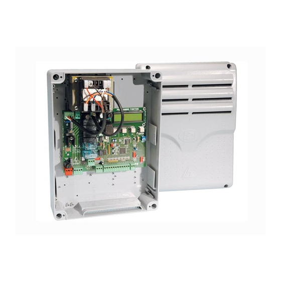
CAME ZL80 (002ZL80) блок управления для секционного привода серии BXE24; питание блока управления осуществляется от сети переменного тока 230 В, 50/60 Гц.; привод, устройства управления и аксессуары работают от 24 В.; допустимая мощность 360 Вт.; потребление в режиме ожидания 55 мA; мощность привода, аксессуаров 24 В 36 Вт; корпус выполнен из ABS-пластика; класс защиты IP54; диапазон рабочих температур от -20…+55°C.
Купить CAME ZL80 в интернет-магазине СЕК-ГРУПП в Москве: Черницынский проезд, д.3, стр.1 (метро Щелковская). Доставка по России.

Особенности CAME ZL80
| EAN | |
| По типу автоматики | для секционных ворот |
| Код производителя | 002ZL80 |
| Тип устройства | блок управления |
| Напряжение питания | 24 В, 220 В |
| Страна производитель | Италия |
Входит в состав комплекта:
Гарантия 3 года
 Италия — страна производства
 Мы официальный дилер CAME

Выходы подключения приводов
24 VDC
Выходы подключения периферии
24 VDC (до 36 Вт)
Совместимость
привода CAME C-BXE24
Максимально допустимая мощность
360 Вт
Потребление в режиме ожидания
55 мА
Класс изоляции контуров
II
Предохранители
питание — 1.6 А; аксессуары — 1.6 А; устройства управления — 1 А; двигатель — 10 А
Материал корпуса
ABS-пластик
Класс защиты корпуса
IP54
Диапазон рабочих температур
-20°C…+55°C
До ТК (СДЭК, ПЭК, Деловые Линии) — 0 Р
Остальные транспортные компании — 750 Р
Заказы от 40 000 Р (по ценам сайта) — 0 Р
В пределах МКАД — 1000 Р (на заказы от 5000 Р — 750 Р)
Негабарит МКАД — 1000 Р
За МКАД — 750 Р + 50Р/км
Негабарит за МКАД — 1500Р + 70Р/км
г. Москва, Черницынский пр-д, д. 3 стр. 1. метро Щелковская
г. Уфа, ул. Трамвайная, д. 2 оф. 1-02
Самовывоз
Доставка курьером СЕК-ГРУПП
Мы правильно определили ваш город?
Безналичный расчет
Оплата осуществляется путем банковского перевода денежных средств с расчетного счета покупателя на наш расчетный счет.
Счет выставляется по запросу в печатном или электронном виде. Счет действителен в течении 3-х банковских дней за исключением оборудования производства компании PERCo.
Оплата наличными в офисах компании
Оплата наличными производится в офисах компании при получении товара со склада по адресам:
- г. Москва, Черницынский проезд, д.3, стр.3
- г. Уфа, Трамвайная улица, д.2, офис 1-02
Оплата наличными при доставке (Москва)
Стоимость заказа передаётся водителю компании при получении товара.