
- Manuals
- Brands
- DAIKIN Manuals
- Air Conditioner
- FTXS25K2V1B
Manuals and User Guides for DAIKIN FTXS25K2V1B. We have 9 DAIKIN FTXS25K2V1B manuals available for free PDF download: Service Manual, Operation Manual, Installation Manual
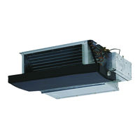
Daikin FTXS25K2V1B Service Manual (462 pages)
Super Multi NX
E / F / G / K-Series
Brand: Daikin
|
Category: Air Conditioner
|
Size: 19.52 MB
Table of Contents
-
Table of Contents
3
-
Introduction
8
-
Safety Cautions
8
-
Used Icons
12
-
-
Part 1 List of Functions
13
-
Cooling Only
14
-
Outdoor Unit
14
-
Indoor Unit
15
-
-
Heat Pump
18
-
Outdoor Unit
18
-
Indoor Unit
19
-
-
-
Part 2 Specifications
26
-
Cooling Only
27
-
Outdoor Unit
27
-
Specifications
28
-
Indoor Unit
29
-
Ceiling Mounted Cassette Type
31
-
Ceiling Suspended Type
32
-
-
-
Heat Pump
34
-
Outdoor Unit
34
-
Indoor Unit
37
-
Floor Standing Type
41
-
Duct Connected Type
44
-
-
-
-
Part 3 Printed Circuit Board Connector Wiring Diagram
49
-
Outdoor Unit
50
-
Indoor Unit
53
-
Ftxg25/35/50Jv1Bw(A)
53
-
Ftxs20/25K2V1B, Ctxs15/35K2V1B
56
-
Ftxs25/35/42/50J2V1B
58
-
Ftxs60/71Gv1B
61
-
Fvxg25/35/50K2V1B
64
-
Fvxs25/35/50Fv1B
67
-
Flxs25/35/50/60Bavmb
69
-
Fdxs25/35E7Vmb, Fdxs50/60C7Vmb
71
-
Fcqg35/50/60Fveb
73
-
Ffq25/35/50/60B9V1B
76
-
Fhq35/50/60Bwv1B
78
-
Fdbq25B8V1
80
-
Fbq35/50/60C8Veb
82
-
-
Wired Remote Controller
85
-
Brc1D528
85
-
Brc1E52A7, Brc1E52B7
86
-
-
-
Part 4 Function and Control
87
-
Indoor Unit Control (RA Models)
88
-
Temperature Control
88
-
Frequency Principle
88
-
Operation Starting Control
90
-
Airflow Direction Control
91
-
Fan Speed Control for Indoor Unit
94
-
RADIANT Operation
95
-
Indoor Unit Fan Control
96
-
Program Dry Operation
97
-
Automatic Operation
98
-
Thermostat Control
99
-
NIGHT SET Mode
101
-
ECONO Operation
102
-
HOME LEAVE Operation
103
-
INTELLIGENT EYE Operation
104
-
2-Area INTELLIGENT EYE Operation
105
-
Inverter POWERFUL Operation
107
-
Multi-Colored Indicator Lamp / TIMER Lamp
107
-
Other Functions
109
-
Weekly Timer Operation
110
-
Brightness Setting of the Indoor Unit Display
110
-
-
-
Indoor Unit Control (SA Models)
111
-
Drain Pump Control
111
-
Thermostat Sensor in Remote Controller
113
-
Freeze Prevention Control
115
-
Hot Start Control (in Heating Operation Only)
116
-
-
Function of Thermistor
117
-
Control Specification
119
-
Mode Hierarchy
119
-
Frequency Control
120
-
Controls at Mode Changing / Start-Up
123
-
Discharge Pipe Temperature Control
124
-
Input Current Control
125
-
Freeze-Up Protection Control
125
-
Heating Peak-Cut Control
126
-
Outdoor Fan Control
127
-
Liquid Compression Protection Function
127
-
Defrost Control
128
-
Low Hz High Pressure Limit
129
-
Outdoor Electronic Expansion Valve Control
129
-
Pressure Equalizing Control
131
-
Malfunctions
134
-
-
-
Part 5 Operation Manual
136
-
System Configuration
137
-
RA Indoor Unit
138
-
FTXG, FTXS-K, CTXS, FVXG Series — ARC466A1, A2, A6
138
-
Name of Parts
139
-
Remote Controller
141
-
-
Model Name Plate
143
-
Signal Receiver
143
-
Indoor Unit On/Off Switch
143
-
Titanium Apatite Photocatalytic
148
-
Preparation before Operation
151
-
Fan Operation
153
-
Operating Conditions
154
-
-
Operation Manual
154
-
Temperature Setting
159
-
Adjusting the Airflow Direction and Rate
160
-
Ra Indoor Unit
161
-
Comfort Airflow Operation
166
-
Powerful Operation
169
-
Outdoor Unit Quiet Operation
171
-
Off Timer Operation
173
-
On Timer Operation
176
-
Note for Multi System
185
-
-
FTXS-J, FTXS-G, FVXS Series — ARC452A1, A3
190
-
Names of Parts
194
-
Names of Parts
196
-
Opening the Front Panel
197
-
To Change the Airflow Rate Setting
201
-
Adjusting the Airflow Direction
202
-
Comfort Airflow and Intelligent Eye Operation
208
-
Quiet Operation
216
-
Copy Mode
224
-
-
FLXS, FDXS Series — ARC433B67, B69
230
-
To Change the Air Flow Rate Setting
234
-
Timer Operation
241
-
-
-
SA Indoor Unit
245
-
Brc1D528
245
-
-
-
Part 6 Service Diagnosis
260
-
Troubleshooting with LED
262
-
Indoor Unit
262
-
Outdoor Unit
264
-
-
Problem Symptoms and Measures
265
-
Service Check Function
266
-
RA Indoor Unit — FTXG, FTXS, CTXS, FVXG, FVXS, FLXS, FDXS Series
266
-
SA Indoor Unit — FCQG, FFQ, FHQ, FDBQ, FBQ Series
275
-
-
Code Indication on Remote Controller
279
-
RA Indoor Unit — FTXG, FTXS, CTXS, FVXG, FVXS, FLXS
279
-
FDXS Series
279
-
-
SA Indoor Unit — FCQG, FFQ, FHQ, FDBQ, FBQ Series
279
-
RA Indoor Unit — FTXG, FTXS, CTXS, FVXG, FVXS, FLXS, FDXS Series
279
-
Sub Codes for SA Indoor Unit
280
-
Outdoor Unit
281
-
-
Troubleshooting for RA Indoor Unit — FTXG, FTXS, CTXS, FVXG, FVXS, FLXS, FDXS Series
282
-
Indoor Unit PCB Abnormality
282
-
Freeze-Up Protection Control or Heating Peak-Cut Control
284
-
Fan Motor or Related Abnormality
286
-
Radiant Panel Temperature Rise, Indoor Electronic Expansion Valve (Motor Operated Valve) Abnormality, Freeze-Up Protection Control (FVXG Series Only)
290
-
Thermistor or Related Abnormality (RA Indoor Unit)
292
-
Front Panel Open / Close Fault (FTXG Series Only)
293
-
Signal Transmission Error (between Indoor Unit and Outdoor Unit)
294
-
Unspecified Voltage (between Indoor Unit and Outdoor Unit)
295
-
-
Troubleshooting for SA Indoor Unit — FCQG, FFQ, FHQ, FDBQ, FBQ Series
296
-
Indoor Unit PCB Abnormality
296
-
Drain Water Level System Abnormality
297
-
Fan Motor or Related Abnormality
299
-
Swing Motor Lock (FHQ Series Only)
301
-
Drain System Abnormality
302
-
Thermistor or Related Abnormality (SA Indoor Unit)
303
-
Remote Controller Thermistor Abnormality
304
-
Signal Transmission Error
305
-
(Between Indoor Unit and Remote Controller)
305
-
Signal Transmission Error (between Indoor Unit and Remote Controller)
305
-
-
Signal Transmission Error
306
-
(Between MAIN Remote Controller and SUB Remote Controller)
306
-
Signal Transmission Error (between MAIN Remote Controller and SUB Remote Controller)
306
-
-
Field Setting Abnormality
307
-
-
Troubleshooting for Outdoor Unit
308
-
Refrigerant Shortage
308
-
Low-Voltage Detection or Over-Voltage Detection
310
-
Signal Transmission Error (on Outdoor Unit PCB)
312
-
Unspecified Voltage (between Indoor Unit and Outdoor Unit)
313
-
Anti-Icing Function in Other Rooms
313
-
Unspecified Voltage (between Indoor Unit and Outdoor Unit) / Anti-Icing Function in Other Rooms
313
-
-
Anti-Icing Function
314
-
Outdoor Unit PCB Abnormality
316
-
OL Activation (Compressor Overload)
317
-
Compressor Lock
318
-
DC Fan Lock
319
-
Input Overcurrent Detection
320
-
Discharge Pipe Temperature Control
321
-
High Pressure Control in Cooling
322
-
Compressor Sensor System Abnormality
323
-
Position Sensor Abnormality
325
-
CT or Related Abnormality
327
-
Thermistor or Related Abnormality (Outdoor Unit)
329
-
Electrical Box Temperature Rise
331
-
Radiation Fin Temperature Rise
333
-
Output Overcurrent Detection
335
-
-
Check
337
-
Thermistor Resistance Check
337
-
Fan Motor Connector Check
338
-
Hall IC Check
339
-
Indoor Electronic Expansion Valve Coil Check
339
-
Power Supply Waveform Check
340
-
Outdoor Electronic Expansion Valve Check
341
-
Four Way Valve Performance Check
342
-
Inverter Unit Refrigerant System Check
342
-
Inverter Checker» Check
343
-
Rotation Pulse Check on the Outdoor Unit PCB
344
-
Installation Condition Check
345
-
Discharge Pressure Check
345
-
Outdoor Fan System Check
346
-
Capacitor Voltage Check
346
-
Power Module Check
347
-
-
-
Part 7 Removal Procedure
348
-
Outdoor Unit: 40-75 Class
349
-
Removal of Outer Panels
349
-
Removal of Electrical Box
353
-
Removal of Pcbs
361
-
Removal of Outdoor Fan / Fan Motor
366
-
Removal of Sound Blankets
368
-
Removal of Coils / Thermistors
372
-
Removal of Distributor
375
-
Removal of Four Way Valve
376
-
Removal of Compressor
377
-
-
Outdoor Unit: 80/90 Class
379
-
Removal of Outer Panels
379
-
Removal of Electrical Box
394
-
Removal of Pcbs
400
-
Removal of Fan Motor
404
-
Removal of Coils / Thermistors
405
-
Removal of Sound Blankets
411
-
Removal of Compressor
414
-
-
-
Part 8 Trial Operation and Field Settings
415
-
Pump down Operation
416
-
Forced Operation
417
-
Wiring Error Check Function
418
-
Trial Operation
420
-
RA Indoor Unit — FTXG, FTXS, CTXS, FVXG, FVXS, FLXS, FDXS Series
420
-
SA Indoor Unit — FCQG, FFQ, FHQ, FDBQ, FBQ Series
422
-
-
Field Settings
424
-
Outdoor Unit
424
-
RA Indoor Unit — FTXG, FTXS, CTXS, FVXG, FVXS, FLXS
427
-
FDXS Series
427
-
Jumper and Switch Settings
430
-
-
SA Indoor Unit — FCQG, FFQ, FHQ, FDBQ, FBQ Series
431
-
-
Application of Silicon Grease to a Power Transistor and a Diode Bridge
435
-
-
Part 9 Appendix
436
-
Piping Diagrams
437
-
Outdoor Unit
437
-
Indoor Unit
442
-
-
Wiring Diagrams
449
-
Outdoor Unit
449
-
Indoor Unit
454
-
-
Advertisement
Daikin FTXS25K2V1B Service Manual (267 pages)
Inverter Multi for 2 Rooms
H-Series / G-Series
Brand: Daikin
|
Category: Heat Pump
|
Size: 13.95 MB
Table of Contents
-
Table of Contents
3
-
Introduction
7
-
Safety Cautions
7
-
Used Icons
11
-
-
Part 1 List of Functions
12
-
Functions
13
-
Function and Control Part
15
-
-
-
Part 2 Specifications
21
-
Indoor Unit
22
-
Specifications
23
-
Floor Standing Type
33
-
Duct Connected Type
36
-
Ceiling Mounted Cassette Type
37
-
-
Outdoor Unit
38
-
-
Part 3 Printed Circuit Board Connector Wiring Diagram
39
-
Indoor Unit
40
-
Ftxg25/35/50Jv1Bw(S)(A)
40
-
Ctxs15/35K2V1B, Ftxs20/25K2V1B
42
-
Ftxs35/42/50K2V1B, Ftxs20/25/35/42/50J2V1B, Atxs20/25/35/42/50G2V1B
44
-
Ftx20/25/35Jv1B, Ftx20/25/35J2V1B, Atx20/25/35Jv1B, Atx20/25/35J2V1B
46
-
Fvxg25/35/50K2V1B
48
-
Fvxs25/35/50Fv1B
50
-
Flxs25/35/50Bavmb
52
-
Fdxs25/35Eavmb, Fdxs25/35E7Vmb, Fdxs50Cvmb, Fdxs50C7Vmb
54
-
Ffq25/35/50B8V1B, Ffq25/35/50B9V1B
56
-
-
Wired Remote Controller
57
-
Brc1D528
57
-
Brc1E51A7
58
-
-
Wireless Remote Controller
59
-
Brc7E530W
59
-
-
Outdoor Unit
60
-
-
Part 4 Function and Control
62
-
Function of RA Indoor Unit
63
-
Temperature Control
63
-
Frequency Principle
63
-
Operation Starting Control
65
-
Airflow Direction Control
66
-
Fan Speed Control for Indoor Unit
69
-
RADIANT Operation
71
-
Program Dry Operation
73
-
Automatic Operation
74
-
Thermostat Control
75
-
NIGHT SET Mode
76
-
ECONO Operation
77
-
HOME LEAVE Operation
78
-
2-Area INTELLIGENT EYE Operation
80
-
INTELLIGENT EYE Operation
82
-
Inverter POWERFUL Operation
83
-
Multi-Colored Indicator Lamp / TIMER Lamp
84
-
Brightness Setting of Indoor Unit Display
85
-
Clock Setting
86
-
WEEKLY TIMER Operation
87
-
Other Functions
93
-
-
Function of SA Indoor Unit
94
-
Drain Pump Control
94
-
Remote Controller
95
-
Thermostat Sensor in Remote Controller
96
-
Freeze Prevention Control
98
-
Hot Start Control (in Heating Operation Only)
99
-
-
Function of Thermistor
100
-
Control Specification
102
-
Mode Hierarchy
102
-
Frequency Control
103
-
Controls at Mode Changing / Start-Up
105
-
Discharge Pipe Temperature Control
106
-
Input Current Control
107
-
Freeze-Up Protection Control
107
-
Heating Peak-Cut Control
108
-
Outdoor Fan Control
109
-
Liquid Compression Protection Function
109
-
Defrost Control
110
-
Outdoor Electronic Expansion Valve Control
111
-
Malfunctions
115
-
-
-
Part 5 Remote Controller
117
-
RA Indoor Unit
118
-
Ftxg25/35/50Jv1Bw(S)(A), Ctxs15/35K2V1B, Ftxs20/25K2V1B
118
-
Mode Button
119
-
Ftxs35/42/50K2V1B
120
-
Ftxs20/25/35/42/50J2V1B
122
-
Atxs20/25/35/42/50G2V1B
124
-
Ftx20/25/35Jv1B, Ftx20/25/35J2V1B, Atx20/25/35Jv1B, Atx20/25/35J2V1B
126
-
Fvxg25/35/50K2V1B
128
-
Fvxs25/35/50Fv1B
130
-
Flxs25/35/50Bavmb
132
-
Fdxs25/35Eavmb, Fdxs25/35E7Vmb, Fdxs50Cvmb, Fdxs50C7Vmb
134
-
-
SA Indoor Unit
136
-
Brc1D528
136
-
Brc1E51A7
139
-
Operation Mode
142
-
Brc7E530W
144
-
-
-
Part 6 Service Diagnosis
145
-
Troubleshooting with LED
147
-
Indoor Unit
147
-
Outdoor Unit
148
-
-
Problem Symptoms and Measures
149
-
Service Check Function
150
-
RA Indoor Unit
150
-
Arc452 Series Remote Controller
153
-
Arc433 Series Remote Controller
156
-
-
SA Indoor Unit
159
-
-
Code Indication on Remote Controller
166
-
RA Indoor Unit
166
-
SA Indoor Unit
166
-
Outdoor Unit
167
-
-
Troubleshooting for RA Indoor Unit
168
-
Indoor Unit PCB Abnormality
168
-
Freeze-Up Protection Control or Heating Peak-Cut Control
170
-
Fan Motor or Related Abnormality
172
-
Radiant Panel Temperature Rise, Indoor Electronic Expansion Valve (Motor Operated Valve) Abnormality, Freeze-Up Protection Control (FVXG Series Only)
176
-
Thermistor or Related Abnormality (RA Indoor Unit)
178
-
Front Panel Open / Close Fault (FTXG Series Only)
179
-
-
Troubleshooting for SA Indoor Unit
180
-
Indoor Unit PCB Abnormality
180
-
Drain Level Control System Abnormality
181
-
Fan Motor (AC Motor) or Related Abnormality
182
-
Drain System Abnormality
183
-
Thermistor or Related Abnormality (SA Indoor Unit)
184
-
Remote Controller Thermistor Abnormality
185
-
Signal Transmission Error (between Indoor Unit and Remote Controller)
186
-
Signal Transmission Error (between MAIN Remote Controller and SUB Remote Controller)
187
-
Field Setting Abnormality
188
-
-
Troubleshooting for Outdoor Unit
189
-
Refrigerant Shortage
189
-
Low-Voltage Detection or Over-Voltage Detection
191
-
Outdoor Unit PCB Abnormality or Signal Transmission Error
193
-
Unspecified Voltage (between Indoor Unit and Outdoor Unit) / Anti-Icing Control in Other Room
196
-
Anti-Icing Control for Indoor Unit
197
-
OL Activation (Compressor Overload)
199
-
Compressor Lock
201
-
DC Fan Lock
202
-
Input Overcurrent Detection
203
-
Discharge Pipe Temperature Control
204
-
High Pressure Control in Cooling
205
-
Compressor Sensor System Abnormality
206
-
Position Sensor Abnormality
207
-
DC Voltage / Current Sensor Abnormality
209
-
Thermistor or Related Abnormality (Outdoor Unit)
210
-
Electrical Box Temperature Rise
212
-
Radiation Fin Temperature Rise
213
-
Output Overcurrent Detection
215
-
-
Check
217
-
Thermistor Resistance Check
217
-
Fan Motor Connector Output Check
218
-
Hall IC Check
219
-
Indoor Electronic Expansion Valve Coil Check
219
-
Power Supply Waveforms Check
220
-
Outdoor Electronic Expansion Valve Check
221
-
Four Way Valve Performance Check
222
-
Inverter Unit Refrigerant System Check
222
-
Inverter Analyzer Check
223
-
Rotating Pulse Input on the Outdoor Unit PCB Check
225
-
Installation Condition Check
226
-
Discharge Pressure Check
226
-
Outdoor Unit Fan System Check
227
-
Main Circuit Short Check
227
-
Power Module Check
228
-
-
-
Part 7 Trial Operation and Field Settings
229
-
Pump down Operation
230
-
Forced Cooling Operation
231
-
Trial Operation
232
-
RA Indoor Unit — FTXG, FTXS, ATXS, FTX, ATX, FVXG, FVXS, FLXS, FDXS Series
232
-
SA Indoor Unit — FFQ Series
234
-
-
Field Settings
236
-
RA Indoor Unit — FTXG, FTXS, ATXS, FTX, ATX, FVXG, FVXS, FLXS, FDXS Series
236
-
SA Indoor Unit — FFQ Series
242
-
Outdoor Unit
250
-
-
Silicon Grease on Power Transistor / Diode Bridge
251
-
-
Part 8 Appendix
252
-
Piping Diagrams
253
-
Indoor Unit
253
-
Outdoor Unit
257
-
-
Wiring Diagrams
258
-
Indoor Unit
258
-
Outdoor Unit
264
-
-
Removal Procedure (Booklet No.)
265
-
Revision History
266
-
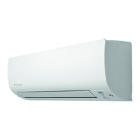
Daikin FTXS25K2V1B Service Manual (184 pages)
Inverter Pair Wall Mounted Type K-Series
Brand: Daikin
|
Category: Air Conditioner
|
Size: 6.93 MB
Table of Contents
-
Table of Contents
3
-
Introduction
6
-
Safety Cautions
6
-
Used Icons
10
-
-
Part 1 List of Functions
11
-
Functions
12
-
Part 2 Specifications
13
-
Specifications
14
-
Part 3 Printed Circuit Board Connector Wiring Diagram
15
-
Indoor Unit
16
-
Outdoor Unit
18
-
Part 4 Function and Control
20
-
Main Functions
21
-
Temperature Control
21
-
Frequency Principle
21
-
Airflow Direction Control
23
-
Fan Speed Control for Indoor Unit
24
-
Program Dry Operation
25
-
Automatic Operation
26
-
Thermostat Control
27
-
NIGHT SET Mode
28
-
ECONO Operation
29
-
INTELLIGENT EYE Operation
30
-
Inverter POWERFUL Operation
31
-
Other Functions
32
-
-
Function of Thermistor
33
-
Control Specification
34
-
Mode Hierarchy
34
-
Frequency Control
35
-
Controls at Mode Changing / Start-Up
37
-
Discharge Pipe Temperature Control
38
-
Input Current Control
39
-
Freeze-Up Protection Control
40
-
Heating Peak-Cut Control
40
-
Outdoor Fan Control
41
-
Liquid Compression Protection Function
41
-
Defrost Control
42
-
Electronic Expansion Valve Control
43
-
Pressure Equalizing Control
44
-
Malfunctions
46
-
-
Part 5 Operation Manual
47
-
System Configuration
48
-
Operation Manual
49
-
Remote Controller
49
-
Quiet Button
50
-
Clock Button
50
-
-
AUTO · DRY · COOL · HEAT · FAN Operation
51
-
Operating Conditions
52
-
Adjusting the Airflow Direction and Rate
53
-
COMFORT AIRFLOW Operation
55
-
INTELLIGENT EYE Operation
56
-
POWERFUL Operation
58
-
OUTDOOR UNIT QUIET Operation
59
-
ECONO Operation
60
-
OFF TIMER Operation
61
-
ON TIMER Operation
62
-
WEEKLY TIMER Operation
63
-
Copy Mode
66
-
-
Part 6 Service Diagnosis
69
-
Troubleshooting with LED
70
-
Indoor Unit
70
-
Outdoor Unit
70
-
-
Problem Symptoms and Measures
71
-
Service Check Function
72
-
Troubleshooting
75
-
Error Codes and Description
75
-
Indoor Unit PCB Abnormality
76
-
Freeze-Up Protection Control or Heating Peak-Cut Control
78
-
Fan Motor (DC Motor) or Related Abnormality
80
-
Thermistor or Related Abnormality (Indoor Unit)
82
-
Refrigerant Shortage
83
-
Low-Voltage Detection or Over-Voltage Detection
85
-
Signal Transmission Error (between Indoor Unit and Outdoor Unit)
87
-
Unspecified Voltage (between Indoor Unit and Outdoor Unit)
89
-
Outdoor Unit PCB Abnormality
90
-
OL Activation (Compressor Overload)
91
-
Compressor Lock
92
-
DC Fan Lock
93
-
Input Overcurrent Detection
94
-
Four Way Valve Abnormality
95
-
Discharge Pipe Temperature Control
97
-
High Pressure Control in Cooling
98
-
Compressor System Sensor Abnormality
99
-
Position Sensor Abnormality
100
-
DC Voltage / Current Sensor Abnormality
102
-
Thermistor or Related Abnormality (Outdoor Unit)
103
-
Electrical Box Temperature Rise
105
-
Radiation Fin Temperature Rise
107
-
Output Overcurrent Detection
109
-
-
Check
111
-
Thermistor Resistance Check
111
-
Fan Motor Connector Output Check
112
-
Power Supply Waveforms Check
112
-
Electronic Expansion Valve Check
113
-
Four Way Valve Performance Check
114
-
Inverter Units Refrigerant System Check
114
-
Inverter Checker» Check
115
-
Rotation Pulse Check on the Outdoor Unit PCB
116
-
Installation Condition Check
117
-
Discharge Pressure Check
117
-
Outdoor Fan System Check
118
-
Main Circuit Short Check
118
-
Power Module Check
119
-
-
Part 7 Removal Procedure
120
-
Indoor Unit
121
-
Removal of Air Filters
121
-
Removal of Horizontal Blade
123
-
Removal of Front Panel
125
-
Removal of Front Grille
126
-
Removal of Vertical Blade Assys
127
-
Removal of Electrical Box
129
-
Removal of Swing Motor / Pcbs
132
-
Removal of Indoor Heat Exchanger
137
-
Removal of Fan Rotor / Fan Motor
140
-
Exchange of Piping Direction (Drain Hose)
143
-
-
Outdoor Unit
144
-
Removal of Outer Panels / Fan Motor
144
-
Removal of Electrical Box
153
-
Removal of Pcbs
156
-
Removal of Reactor / Partition Plate
164
-
Removal of Sound Blankets
166
-
Removal of Four Way Valve
168
-
Removal of Compressor
171
-
-
Part 8 Trial Operation and Field Settings
173
-
Pump down Operation
174
-
Forced Cooling Operation
175
-
Trial Operation
176
-
Field Settings
177
-
Model Type Setting
177
-
When 2 Units Are Installed in 1 Room
177
-
Standby Electricity Saving
178
-
Facility Setting Jumper (Cooling at Low Outdoor Temperature)
178
-
Jumper Settings
179
-
-
Application of Silicon Grease to a Power Transistor and a Diode Bridge
180
-
Part 9 Appendix
181
-
Piping Diagrams
182
-
Indoor Unit
182
-
Outdoor Unit
182
-
-
Wiring Diagrams
183
-
Indoor Unit
183
-
Outdoor Unit
183
-
Advertisement
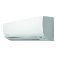
Daikin FTXS25K2V1B Service Manual (131 pages)
Inverter Pair Wall Mounted Type FTXS/ATXS-K Series
Brand: Daikin
|
Category: Air Conditioner
|
Size: 4.03 MB
Table of Contents
-
Table of Contents
3
-
Safety Cautions
6
-
Warnings and Cautions Regarding Safety of Workers
6
-
Warnings and Cautions Regarding Safety of Users
8
-
-
Icons Used
10
-
Part 1 List of Functions
11
-
Functions
12
-
-
Part 2 Specifications
15
-
Specifications
16
-
-
Part 3 Printed Circuit Board Connector Wiring Diagram
21
-
Indoor Unit
22
-
Outdoor Unit
24
-
Rxs20/25K2V1B, Rxs20/25K3V1B, Rxs20/25L2V1B, Arxs25L2V1B
24
-
Rxs20/25L3V1B, Arxs25L3V1B
26
-
-
-
Part 4 Functions and Control
27
-
Main Functions
28
-
Temperature Control
28
-
Frequency Principle
28
-
Airflow Direction Control
30
-
Fan Speed Control for Indoor Unit
31
-
Program Dry Operation
32
-
Automatic Operation
33
-
Thermostat Control
34
-
NIGHT SET Mode
35
-
ECONO Operation
35
-
INTELLIGENT EYE Operation
36
-
Inverter POWERFUL Operation
37
-
Clock Setting
38
-
WEEKLY TIMER Operation
39
-
Other Functions
45
-
-
Thermistor Functions
46
-
Control Specification
47
-
Mode Hierarchy
47
-
Frequency Control
48
-
Controls at Mode Changing / Start-Up
50
-
Compressor Protection Function
51
-
Discharge Pipe Temperature Control
52
-
Input Current Control
53
-
Freeze-Up Protection Control
54
-
Heating Peak-Cut Control
54
-
Outdoor Fan Control
55
-
Liquid Compression Protection Function
55
-
Defrost Control
56
-
Electronic Expansion Valve Control
57
-
Pressure Equalizing Control
58
-
Malfunctions
60
-
-
-
Part 5 Remote Controller
61
-
Remote Controller
62
-
Mode Button
63
-
Quiet Button
63
-
-
-
Part 6 Service Diagnosis
64
-
General Problem Symptoms and Check Items
65
-
Troubleshooting with LED
66
-
Indoor Unit
66
-
Outdoor Unit
66
-
-
Service Diagnosis
67
-
Troubleshooting
70
-
Error Codes and Description
70
-
Indoor Unit PCB Abnormality
71
-
Freeze-Up Protection Control / Heating Peak-Cut Control
72
-
Fan Motor (DC Motor) or Related Abnormality
73
-
Thermistor or Related Abnormality (Indoor Unit)
75
-
Refrigerant Shortage
76
-
Low-Voltage Detection or Over-Voltage Detection
78
-
Signal Transmission Error (between Indoor Unit and Outdoor Unit)
80
-
Unspecified Voltage (between Indoor Unit and Outdoor Unit)
82
-
Outdoor Unit PCB Abnormality
83
-
OL Activation (Compressor Overload)
85
-
Compressor Lock
87
-
DC Fan Lock
88
-
Input Overcurrent Detection
89
-
Four Way Valve Abnormality
90
-
Discharge Pipe Temperature Control
92
-
High Pressure Control in Cooling
93
-
Compressor System Sensor Abnormality
94
-
Position Sensor Abnormality
95
-
DC Voltage / Current Sensor Abnormality
97
-
Thermistor or Related Abnormality (Outdoor Unit)
98
-
Electrical Box Temperature Rise
100
-
Radiation Fin Temperature Rise
101
-
Output Overcurrent Detection
102
-
-
Check
104
-
Thermistor Resistance Check
104
-
Indoor Fan Motor Connector Output Check
105
-
Power Supply Waveforms Check
106
-
Electronic Expansion Valve Check
106
-
Four Way Valve Performance Check
107
-
Inverter Unit Refrigerant System Check
107
-
Inverter Analyzer Check
108
-
Rotation Pulse Check on the Outdoor Unit PCB
110
-
Installation Condition Check
111
-
Discharge Pressure Check
111
-
Outdoor Fan System Check
112
-
Main Circuit Short Check
112
-
Power Module Check
113
-
-
-
Part 7 Trial Operation and Field Settings
115
-
Pump down Operation
116
-
Forced Cooling Operation
117
-
Trial Operation
118
-
Field Settings
119
-
Model Type Setting
119
-
When 2 Units Are Installed in 1 Room
119
-
Standby Electricity Saving
120
-
Facility Setting (Cooling at Low Outdoor Temperature)
120
-
Jumper Settings
121
-
-
Silicone Grease on Power Transistor / Diode Bridge
122
-
-
Part 8 Appendix
123
-
Piping Diagrams
124
-
Indoor Unit
124
-
Outdoor Unit
125
-
-
Wiring Diagrams
126
-
Indoor Unit
126
-
Outdoor Unit
128
-
-
DAIKIN FTXS25K2V1B Operation Manual (44 pages)
DAIKIN ROOM AIR CONDITIONER
Brand: DAIKIN
|
Category: Air Conditioner
|
Size: 12.26 MB
Table of Contents
-
Operation Manual
1
-
Intelligent Eye
2
-
Table of Contents
3
-
Safety Precautions
4
-
Front Panel
6
-
Model Name
6
-
Operation Lamp
6
-
Signal Receiver
6
-
-
Name of Parts
6
-
Front Cover
8
-
Quiet Button
9
-
Clock Button
9
-
-
Preparation before Operation
10
-
AUTO · DRY · COOL · HEAT · FAN Operation
12
-
Operating Conditions
13
-
Adjusting the Airflow Direction and Rate
14
-
COMFORT AIRFLOW Operation
16
-
INTELLIGENT EYE Operation
17
-
POWERFUL Operation
19
-
Outdoor Unit Quiet
20
-
OUTDOOR UNIT QUIET Operation
20
-
ECONO Operation
21
-
OFF TIMER Operation
22
-
ON TIMER Operation
23
-
WEEKLY TIMER Operation
24
-
Copy Mode
27
-
-
Note for Multi System
30
-
Care and Cleaning
32
-
Removing the Front Panel
33
-
Before a Long Idle Period
36
-
Important Information Regarding the Refrigerant Used
36
-
-
Troubleshooting
37
-
Indoor Unit
37
-
Outdoor Unit
37
-
During Operation
38
-
Call the Service Shop Immediately
40
-
Disposal Requirements
40
-
Fault Diagnosis by Remote Controller
41
-
Daikin FTXS25K2V1B Operation Manual (44 pages)
Brand: Daikin
|
Category: Air Conditioner
|
Size: 6.95 MB
Table of Contents
-
Operation Manual
1
-
Intelligent Eye
2
-
Table of Contents
3
-
Safety Precautions
4
-
Name of Parts
6
-
Front Cover
8
-
Quiet Button
9
-
Clock Button
9
-
-
Preparation before Operation
10
-
AUTO · DRY · COOL · HEAT · FAN Operation
12
-
Operating Conditions
13
-
Adjusting the Airflow Direction and Rate
14
-
COMFORT AIRFLOW Operation
16
-
INTELLIGENT EYE Operation
17
-
POWERFUL Operation
19
-
Outdoor Unit Quiet
20
-
Operation
20
-
ECONO Operation
21
-
OFF TIMER Operation
22
-
ON TIMER Operation
23
-
WEEKLY TIMER Operation
24
-
Copy Mode
27
-
-
Note for Multi System
30
-
Care and Cleaning
32
-
Removing the Front Panel
33
-
Air Filter
34
-
Before a Long Idle Period
36
-
Important Information Regarding the Refrigerant Used
36
-
Indoor Unit
37
-
Outdoor Unit
37
-
-
Troubleshooting
37
-
During Operation
38
-
Call the Service Shop Immediately
40
-
Disposal Requirements
40
-
Fault Diagnosis by Remote Controller
41
-
Daikin FTXS25K2V1B Service Manual (28 pages)
Brand: Daikin
|
Category: Air Conditioner
|
Size: 3.25 MB
Table of Contents
-
Table of Contents
3
-
Removal of Air Filters
4
-
Removal of Horizontal Blade
6
-
Removal of Front Panel
8
-
Removal of Front Grille
9
-
Removal of Vertical Blade Assys
10
-
Removal of Electrical Box
12
-
Removal of Swing Motor / Pcbs
15
-
Removal of Indoor Heat Exchanger
20
-
Removal of Fan Rotor / Fan Motor
23
-
Exchange of Piping Direction (Drain Hose)
26

DAIKIN FTXS25K2V1B Installation Manual (18 pages)
ROOM AIR CONDITIONER R410A Split Series
Brand: DAIKIN
|
Category: Air Conditioner
|
Size: 5 MB
Table of Contents
-
Installation Manual
1
-
Safety Precautions
5
-
Choosing an Installation Site
6
-
Indoor Unit
6
-
Wireless Remote Controller
6
-
Preparation before Installation
7
-
How to Set the Different Addresses
7
-
Indoor Unit Installation Drawings
8
-
Indoor Unit Installation
9
-
Installing Indoor Unit
9
-
Left-Side, Left-Back, or Left-Bottom Piping
11
-
How to Replace the Drain Plug and Drain Hose
11
-
Drain Piping
14
-
Refrigerant Piping Work
14
-
Refrigerant Piping
15
Daikin FTXS25K2V1B Service Manual (21 pages)
1.5/2.0/2.5/3.5 kW Class
Brand: Daikin
|
Category: Air Conditioner
|
Size: 2.61 MB
Table of Contents
-
Table of Contents
3
-
Air Filters
4
-
Horizontal Blade
5
-
Front Panel
6
-
Front Grille
7
-
Vertical Blade Assys
8
-
Electrical Box
9
-
Swing Motor / Pcbs
11
-
Indoor Heat Exchanger
15
-
Fan Rotor / Fan Motor
18
Advertisement
Related Products
-
Daikin Inverter FTXS25KVMA
-
Daikin FTXS25K3V1B
-
Daikin FTXS25K
-
Daikin FTXS25KVM
-
Daikin FTXS25KVLT
-
DAIKIN Super Multi NX FTXS25G2V1B
-
Daikin FTXS25DVMW
-
Daikin FTXS25D3VMW(L)
-
Daikin FTXS25FV2CW
-
Daikin FTXS25GVMV
DAIKIN Categories

Air Conditioner
Heat Pump
Remote Control
Chiller
Controller
More DAIKIN Manuals
 ПРЕДОСТЕРЕЖЕНИЕ
•Не размещайте восприимчивые к влаге предметы непосредственно под внутренним или наружным агрегатом. При определенных условиях конденсация на основном блоке или трубах с хладагентом, загрязненный воздушный фильтр или засоренный дренаж могут вызвать капание, что приведет к загрязнению или выходу из строя указанных предметов.
•После длительного использования проверьте подставку и ее крепление на предмет возможного повреждения. Если повреждение не устранить, блок может упасть и травмировать человека.
•Во избежание травмы не прикасайтесь к воздухозаборному отверстию или алюминиевым ребрам внутреннего или наружного агрегата.
•Устройство не предназначено для использования маленькими детьми или слабыми людьми без наблюдения. Это может привести к телесным повреждениям и причинению вреда здоровью.
•За маленькими детьми необходимо следить, чтобы они не играли с блоком или пультом ДУ. Если ребенок случайно включит аппарат, это может привести к нарушению функционирования аппарата, а также к травме ребенка.
•Не допускайте сотрясений внутреннего и наружного агрегата, поскольку это может привести к повреждению изделия.
•Легковоспламеняющиеся предметы, такие как аэрозольные баллончики, следует размещать не ближе, чем на расстоянии 1 м от отверстия для выпуска воздуха.
Аэрозольные баллончики могут взрываться в результате воздействия горячего воздуха из внутреннего или наружного агрегата.
•Не допускайте, чтобы домашние животные мочились на кондиционер. В противном случае возможны поражение электрическим током или пожар.
•Во избежание уменьшения содержания кислорода обеспечьте адекватную вентиляцию помещения, если вместе с кондиционером в нем применяется оборудование, использование которого связано с возникновением открытого огня.
•Перед чисткой выключите кондиционер и выньте шнур электропитания из сетевой розетки. В противном случае возможны поражение электрическим током или травма.
•Подключайте кондиционер только к указанной цепи электропитания. Отличные от указанного источники питания могут стать причиной поражения электрическим током, перегрева и пожара.
•Отрегулируйте сливной шланг, чтобы обеспечить плавный слив. Неправильный слив может вызвать намокание мебели, здания и т.п.
•Не размещайте в непосредственной близости от наружного блока различные предметы и не допускайте скопления вокруг него листьев и другого мусора. Листья – питательная среда для мелких животных, которые могут проникнуть в блок. Оказавшись в блоке, такие организмы могут вызвать сбои в его работе, задымление или возгорание при вступлении в контакт с электрическими деталями.
•Не размещайте предметы рядом с внутренним агрегатом.
Они могут оказать негативное влияние на характеристики, качество и срок службы кондиционера.
•Данное устройство не предназначено для эксплуатации лицами с ограниченными физическими, сенсорными или умственными возможностями, а равно и теми, у кого нет соответствующих знаний. Такие лица допускаются к
эксплуатации устройства только под наблюдением или руководством лица, несущего ответственность за их безопасность.
•Оборудование должно быть недоступно детям, чтобы они не играли с устройствами.
•Уровень звукового давления: менее 70 дБ (A).
• Во избежание поражения электрическим током не работайте с мокрыми руками.
• Не промывайте кондиционер водой, так как это может привести к поражению электрическим током или пожару.
• Не следует ставить емкости с водой (вазы и т.п.) на блок, так как это может привести к поражению электрическим током или пожару.
Место установки.
■■Перед монтажом кондиционера в следующих типах окружающих сред проконсультируйтесь с дилером.
•Окружающая среда, в которой присутствует масло, водяной пар или сажа.
•Окружающая среда с соленой атмосферой, например прибрежные зоны.
•Места где происходит образование сероводорода, такие как термальные минеральные источники.
•Места, в которых снег может заблокировать наружный агрегат.
•Агрегат расположен на расстоянии не менее 1 м от телевизоров и радиоприемников (агрегат может создавать помехи для изображения или звука).
•Вода из наружного агрегата должна сливаться в место с нормальным дренажом.
Учитывайте неудобства для соседей из-за шума.
■■Для монтажа выберите место, которое удовлетворяет следующим требованиям.
•Выберите место, достаточно прочное, чтобы выдержать вес агрегата, где не будет усиливаться шум от работы и вибрация.
•Место, в котором выпускаемый из наружного агрегата воздух или шум от работы не будут создавать неудобства для соседей.
Электротехнические работы.
• Для питания кондиционера используйте отдельную цепь электропитания.
Перемещение системы.
•Для перемещения кондиционера в другое место требуются специальные знания и опыт. Обратитесь к дилеру, если требуется выполнить перемещение или модернизацию.
-
Инструкции по эксплуатации
1

Daikin FTXS25K инструкция по эксплуатации
(44 страницы)
- Языки:Русский
-
Тип:
PDF -
Размер:
5.4 MB -
Описание:
Сплит-система
Просмотр
На NoDevice можно скачать инструкцию по эксплуатации для Daikin FTXS25K. Руководство пользователя необходимо для ознакомления с правилами установки и эксплуатации Daikin FTXS25K. Инструкции по использованию помогут правильно настроить Daikin FTXS25K, исправить ошибки и выявить неполадки.
Посмотреть инструкция для Daikin FTXS25K2V1B бесплатно. Руководство относится к категории кондиционеры, 2 человек(а) дали ему среднюю оценку 6.8. Руководство доступно на следующих языках: английский. У вас есть вопрос о Daikin FTXS25K2V1B или вам нужна помощь? Задайте свой вопрос здесь
Не можете найти ответ на свой вопрос в руководстве? Вы можете найти ответ на свой вопрос ниже, в разделе часто задаваемых вопросов о Daikin FTXS25K2V1B.
Как часто следует прочищать фильтры кондиционера Daikin?
Инструкция Daikin FTXS25K2V1B доступно в русский?
Не нашли свой вопрос? Задайте свой вопрос здесь