
инструкцияHikvision DS-KV8113-WME1(B)

Video Intercom Villa Door Staon
User Manual
Посмотреть инструкция для Hikvision DS-KV8113-WME1(B) бесплатно. Руководство относится к категории домофон-системы, 11 человек(а) дали ему среднюю оценку 8.3. Руководство доступно на следующих языках: английский. У вас есть вопрос о Hikvision DS-KV8113-WME1(B) или вам нужна помощь? Задайте свой вопрос здесь
- Legal Information
- Symbol Conventions
- Safety Instruction
- Regulatory Information
- 1 Appearance
- 2 Terminal and Wiring Description
- 3 Installation
- 4 Activation
- 5 Remote Configuration via Web
- 6 Configuration via Client Software
- A. Communication Matrix and Device Command

Главная
| Hikvision | |
| DS-KV8113-WME1(B) | DS-KV8113-WME1(B) | |
| домофон-система | |
| 6941264069225 | |
| английский | |
| Руководство пользователя (PDF) |
Технические характеристики
| Технология подключения | Проводная |
| Цветной | Да |
| Громкоговоритель | Да |
| Встроенные колонки | Да |
| Кодеки голоса | G.711u |
| Настенный | Да |
| Встроенный микрофон | Да |
| Количество кнопок | 4 кнопок(а) |
| Функция обнаружения движения | Да |
| Количество поддерживаемых дисплеев | — |
| Максимальное количество поддерживаемых камер | — |
| Эхоподавление | Да |
| Потоковая мощность | Да |
Камера
| Максимальное разрешение видео | 1920 x 1080 пикселей |
| Поддерживаемые видеоформаты | 720p, 1080p |
| Максимальная частота кадров | 30 fps |
| Угол обзора по горизонтали | 129 ° |
| Угол обзора по вертикали | 75 ° |
| Мегапиксели | 2 MP |
Дизайн
| IK код | IK08 |
| Цвет товара | Black, Grey |
| International Protection (IP) код | IP65 |
| Поддерживаемое размещение | Вертикально |
| Назначение | Вне помещения |
| Светодиодные индикаторы | Да |
Ночное видение
| Ночное видение | Да |
| Дистанция ночного видения | 3 m |
| Тип светодиода | Инфракрасный |
Энергопитание
| Тип питания наружного блока | Постоянный ток |
| Выходное напряжение адаптера переменного тока | 12 V |
| Потребляемая мощность (в обычном режиме) | 10 W |
Экран
Условия эксплуатации
| Диапазон температур при эксплуатации | -40 — 53 °C |
| Диапазон относительной влажности при эксплуатации | 10 — 95 % |
программное обеспечение
| Установленная операционная система | Linux |
Данные об упаковке
| Внутренний блок в комплекте | Нет |
| Наружный блок в комплекте | Да |
| Ширина упаковки | 140 mm |
| Глубина упаковки | 120 mm |
| Высота упаковки | 220 mm |
Сеть
| Питание по Ethernet (PoE) | Да |
| Стандарты сети | IEEE 802.3af |
| Поддерживаемые сетевые протоколы | TCP/IP, RSTP |
| Тип Ethernet интерфейса | Быстрый Ethernet |
| Скорость передачи данных Ethernet LAN | 10, 100 Мбит/с |
| Количество портов Ethernet LAN ( RJ-45) | 1 |
Вес и размеры
| Вес | 385 g |
| Ширина | 91 mm |
| Глубина | 29 mm |
| Высота | 174 mm |
показать больше
Не можете найти ответ на свой вопрос в руководстве? Вы можете найти ответ на свой вопрос ниже, в разделе часто задаваемых вопросов о Hikvision DS-KV8113-WME1(B).
Какой вес Hikvision DS-KV8113-WME1(B)?
Какой размер экрана Hikvision DS-KV8113-WME1(B)?
Какая высота Hikvision DS-KV8113-WME1(B)?
Какая ширина Hikvision DS-KV8113-WME1(B)?
Какая толщина Hikvision DS-KV8113-WME1(B)?
Инструкция Hikvision DS-KV8113-WME1(B) доступно в русский?
Не нашли свой вопрос? Задайте свой вопрос здесь
View a manual of the Hikvision DS-KV8113-WME1(B) below. All manuals on ManualsCat.com can be viewed completely free of charge. By using the ‘Select a language’ button, you can choose the language of the manual you want to view.
Page: 1
Video Intercom Villa Door Station
User Manual
Page: 2
Legal Information
©2020 Hangzhou Hikvision Digital Technology Co., Ltd. All rights reserved.
About this Manual
The Manual includes instructions for using and managing the Product.
Pictures, charts, images and all other information hereinafter are for
description and explanation only. The information contained in the Manual
is subject to change, without notice, due to firmware updates or other
reasons. Please find the latest version of this Manual at the Hikvision
website ( https://www.hikvision.com/ ).
Please use this Manual with the guidance and assistance of professionals
trained in supporting the Product.
Trademarks
and other Hikvision’s trademarks and logos are the
properties of Hikvision in various jurisdictions.
Other trademarks and logos mentioned are the properties of their
respective owners.
Disclaimer
TO THE MAXIMUM EXTENT PERMITTED BY APPLICABLE LAW, THIS MANUAL
AND THE PRODUCT DESCRIBED, WITH ITS HARDWARE, SOFTWARE AND
FIRMWARE, ARE PROVIDED “AS IS” AND “WITH ALL FAULTS AND ERRORS”.
HIKVISION MAKES NO WARRANTIES, EXPRESS OR IMPLIED, INCLUDING
WITHOUT LIMITATION, MERCHANTABILITY, SATISFACTORY QUALITY, OR
FITNESS FOR A PARTICULAR PURPOSE. THE USE OF THE PRODUCT BY YOU IS
AT YOUR OWN RISK. IN NO EVENT WILL HIKVISION BE LIABLE TO YOU FOR
ANY SPECIAL, CONSEQUENTIAL, INCIDENTAL, OR INDIRECT DAMAGES,
INCLUDING, AMONG OTHERS, DAMAGES FOR LOSS OF BUSINESS PROFITS,
BUSINESS INTERRUPTION, OR LOSS OF DATA, CORRUPTION OF SYSTEMS, OR
LOSS OF DOCUMENTATION, WHETHER BASED ON BREACH OF CONTRACT,
TORT (INCLUDING NEGLIGENCE), PRODUCT LIABILITY, OR OTHERWISE, IN
Video Intercom Villa Door Station User Manual
i
Page: 3
CONNECTION WITH THE USE OF THE PRODUCT, EVEN IF HIKVISION HAS
BEEN ADVISED OF THE POSSIBILITY OF SUCH DAMAGES OR LOSS.
YOU ACKNOWLEDGE THAT THE NATURE OF INTERNET PROVIDES FOR
INHERENT SECURITY RISKS, AND HIKVISION SHALL NOT TAKE ANY
RESPONSIBILITIES FOR ABNORMAL OPERATION, PRIVACY LEAKAGE OR
OTHER DAMAGES RESULTING FROM CYBER-ATTACK, HACKER ATTACK, VIRUS
INSPECTION, OR OTHER INTERNET SECURITY RISKS; HOWEVER, HIKVISION
WILL PROVIDE TIMELY TECHNICAL SUPPORT IF REQUIRED.
YOU AGREE TO USE THIS PRODUCT IN COMPLIANCE WITH ALL APPLICABLE
LAWS, AND YOU ARE SOLELY RESPONSIBLE FOR ENSURING THAT YOUR USE
CONFORMS TO THE APPLICABLE LAW. ESPECIALLY, YOU ARE RESPONSIBLE,
FOR USING THIS PRODUCT IN A MANNER THAT DOES NOT INFRINGE ON THE
RIGHTS OF THIRD PARTIES, INCLUDING WITHOUT LIMITATION, RIGHTS OF
PUBLICITY, INTELLECTUAL PROPERTY RIGHTS, OR DATA PROTECTION AND
OTHER PRIVACY RIGHTS. YOU SHALL NOT USE THIS PRODUCT FOR ANY
PROHIBITED END-USES, INCLUDING THE DEVELOPMENT OR PRODUCTION
OF WEAPONS OF MASS DESTRUCTION, THE DEVELOPMENT OR
PRODUCTION OF CHEMICAL OR BIOLOGICAL WEAPONS, ANY ACTIVITIES IN
THE CONTEXT RELATED TO ANY NUCLEAR EXPLOSIVE OR UNSAFE NUCLEAR
FUEL-CYCLE, OR IN SUPPORT OF HUMAN RIGHTS ABUSES.
IN THE EVENT OF ANY CONFLICTS BETWEEN THIS MANUAL AND THE
APPLICABLE LAW, THE LATER PREVAILS.
Video Intercom Villa Door Station User Manual
ii
Page: 4
Symbol Conventions
The symbols that may be found in this document are defined as follows.
Symbol Description
Danger
Indicates a hazardous situation which, if not avoided, will or
could result in death or serious injury.
Caution
Indicates a potentially hazardous situation which, if not
avoided, could result in equipment damage, data loss,
performance degradation, or unexpected results.
Note Provides additional information to emphasize or
supplement important points of the main text.
Video Intercom Villa Door Station User Manual
iii
Page: 5
Safety Instruction
Warning
• The working temperature of the device is from -10 ºC to 55 ºC.
• All the electronic operation should be strictly compliance with the electrical
safety regulations, fire prevention regulations and other related regulations in
your local region.
• Please use the power adapter, which is provided by normal company. The power
consumption cannot be less than the required value.
• Do not connect several devices to one power adapter as adapter overload may
cause over-heat or fire hazard.
• Please make sure that the power has been disconnected before you wire, install
or dismantle the device.
• When the product is installed on wall or ceiling, the device shall be firmly fixed.
• If smoke, odors or noise rise from the device, turn off the power at once and
unplug the power cable, and then please contact the service center.
• If the product does not work properly, please contact your dealer or the nearest
service center. Never attempt to disassemble the device yourself. (We shall not
assume any responsibility for problems caused by unauthorized repair or
maintenance.)
Caution
• Do not drop the device or subject it to physical shock, and do not expose it to
high electromagnetism radiation. Avoid the equipment installation on vibrations
surface or places subject to shock (ignorance can cause equipment damage).
• Do not place the device in extremely hot (refer to the specification of the device
for the detailed operating temperature), cold, dusty or damp locations, and do
not expose it to high electromagnetic radiation.
• The device cover for indoor use shall be kept from rain and moisture.
• Exposing the equipment to direct sun light, low ventilation or heat source such
as heater or radiator is forbidden (ignorance can cause fire danger).
• Do not aim the device at the sun or extra bright places. A blooming or smear
may occur otherwise (which is not a malfunction however), and affecting the
endurance of sensor at the same time.
Video Intercom Villa Door Station User Manual
iv
Page: 6
• Please use the provided glove when open up the device cover, avoid direct
contact with the device cover, because the acidic sweat of the fingers may erode
the surface coating of the device cover.
• Please use a soft and dry cloth when clean inside and outside surfaces of the
device cover, do not use alkaline detergents.
• Please keep all wrappers after unpack them for future use. In case of any failure
occurred, you need to return the device to the factory with the original wrapper.
Transportation without the original wrapper may result in damage on the device
and lead to additional costs.
• Improper use or replacement of the battery may result in hazard of explosion.
Replace with the same or equivalent type only. Dispose of used batteries
according to the instructions provided by the battery manufacturer.
• Input voltage should meet both the SELV and the Limited Power Source
according to 60950-1 standard.
• The power supply must conform to LPS. The recommended adaptor models and
manufacturers are shown as below. Use the attached adapter, and do not
change the adaptor randomly.
Model Manufacturer Standard
ADS-24S-12 1224GPCN SHENZHEN HONOR
ELECTRONIC CO.,LTD
CEE
G0549-240-050 SHENZHEN GOSPELL DIGITAL
TECHNOLOGY CO.,LTD
CEE
TS-A018-120015Ec SHENZHEN TRANSIN
TECHNOLOGIES CO., LTD
CEE
Video Intercom Villa Door Station User Manual
v
Page: 7
Regulatory Information
FCC Information
Please take attention that changes or modification not expressly approved
by the party responsible for compliance could void the user’s authority to
operate the equipment.
FCC compliance: This equipment has been tested and found to comply with
the limits for a Class B digital device, pursuant to part 15 of the FCC Rules.
These limits are designed to provide reasonable protection against harmful
interference in a residential installation. This equipment generates, uses and
can radiate radio frequency energy and, if not installed and used in
accordance with the instructions, may cause harmful interference to radio
communications. However, there is no guarantee that interference will not
occur in a particular installation. If this equipment does cause harmful
interference to radio or television reception, which can be determined by
turning the equipment off and on, the user is encouraged to try to correct
the interference by one or more of the following measures:
—Reorient or relocate the receiving antenna.
—Increase the separation between the equipment and receiver.
—Connect the equipment into an outlet on a circuit different from that to
which the receiver is connected.
—Consult the dealer or an experienced radio/TV technician for help
FCC Conditions
This device complies with part 15 of the FCC Rules. Operation is subject to
the following two conditions:
1. This device may not cause harmful interference.
2. This device must accept any interference received, including interference
that may cause undesired operation.
Video Intercom Villa Door Station User Manual
vi
Page: 8
EU Conformity Statement
This product and — if applicable — the supplied accessories too are
marked with «CE» and comply therefore with the applicable
harmonized European standards listed under the EMC Directive
2014/30/EU, the RoHS Directive 2011/65/EU
2012/19/EU (WEEE directive): Products marked with this symbol
cannot be disposed of as unsorted municipal waste in the
European Union. For proper recycling, return this product to your
local supplier upon the purchase of equivalent new equipment, or
dispose of it at designated collection points. For more information
see: www.recyclethis.info
2006/66/EC (battery directive): This product contains a battery
that cannot be disposed of as unsorted municipal waste in the
European Union. See the product documentation for specific
battery information. The battery is marked with this symbol,
which may include lettering to indicate cadmium (Cd), lead (Pb),
or mercury (Hg). For proper recycling, return the battery to your
supplier or to a designated collection point. For more information
see:www.recyclethis.info
Industry Canada ICES-003 Compliance
This device meets the CAN ICES-3 (B)/NMB-3(B) standards requirements.
Video Intercom Villa Door Station User Manual
vii
Page: 9
Contents
1 Appearance …………………………………………………………………………………… 1
2 Terminal and Wiring Description ………………………………………………………. 7
2.1 Terminal Description …………………………………………………………………………….. 7
2.2 Wiring Description ……………………………………………………………………………….. 8
2.2.1 Door Lock Wiring ………………………………………………………………………….. 8
2.2.2 Door Contact Wiring ……………………………………………………………………… 9
2.2.3 Exit Button Wiring ………………………………………………………………………… 9
2.2.4 Alarm Input Device Wiring …………………………………………………………… 10
3 Installation …………………………………………………………………………………… 11
3.1 Accessory Introduction ……………………………………………………………………….. 11
3.2 Surface Mounting with Protective Shield ……………………………………………….. 11
3.3 Surface Mounting without Protective Shield ………………………………………….. 13
3.4 Flush Mounting with Protective Shield ………………………………………………….. 15
3.5 Flush Mounting without Protective Shield ……………………………………………… 17
4 Activation ……………………………………………………………………………………. 20
4.1 Activate Device via Web ………………………………………………………………………. 20
4.2 Activate Device via Client Software ……………………………………………………….. 20
4.3 Edit Network Parameters …………………………………………………………………….. 21
5 Remote Configuration via Web ………………………………………………………. 22
5.1 Live View …………………………………………………………………………………………… 22
5.2 User Management ……………………………………………………………………………… 22
5.3 Number Settings ………………………………………………………………………………… 23
Video Intercom Villa Door Station User Manual
viii
Page: 10
5.4 Device Management …………………………………………………………………………… 23
5.5 Parameters Settings ……………………………………………………………………………. 23
5.5.1 Local Parameters Settings …………………………………………………………….. 24
5.5.2 System Settings …………………………………………………………………………… 25
5.5.3 Network Settings ………………………………………………………………………… 28
5.5.4 Video & Audio Settings ………………………………………………………………… 31
5.5.5 Image Settings ……………………………………………………………………………. 34
5.5.6 Event Settings …………………………………………………………………………….. 37
5.5.7 Schedule Settings ………………………………………………………………………… 40
5.5.8 Intercom Settings ………………………………………………………………………… 40
5.5.9 Access Control Settings ………………………………………………………………… 43
6 Configuration via Client Software ……………………………………………………. 46
6.1 Device Management …………………………………………………………………………… 46
6.1.1 Add Online Device ………………………………………………………………………. 46
6.1.2 Add Device by IP Address …………………………………………………………….. 47
6.1.3 Add Device by IP Segment ……………………………………………………………. 47
6.2 Live View via Door Station …………………………………………………………………… 48
6.3 Organization Management ………………………………………………………………….. 48
6.3.1 Add Organization ………………………………………………………………………… 48
6.3.2 Modify and Delete Organization ……………………………………………………. 49
6.4 Person Management …………………………………………………………………………… 49
6.4.1 Add Person ………………………………………………………………………………… 49
6.4.2 Modify and Delete Person ……………………………………………………………. 51
6.4.3 Change Person to Other Organization ……………………………………………. 51
Video Intercom Villa Door Station User Manual
ix
Page: 11
6.4.4 Import and Export Person Information ………………………………………….. 51
6.4.5 Get Person Information from Device ……………………………………………… 52
6.4.6 Issue Card in Batch ……………………………………………………………………… 52
6.4.7 Permission Settings ……………………………………………………………………… 54
6.5 Video Intercom Settings ………………………………………………………………………. 55
6.5.1 Receive Call from Door Station ……………………………………………………… 55
6.5.2 Release Notice ……………………………………………………………………………. 56
6.5.3 Search Video Intercom Information ………………………………………………. 57
6.5.4 Upload Armed Information ………………………………………………………….. 58
A. Communication Matrix and Device Command ………………………………… 60
Video Intercom Villa Door Station User Manual
x
Page: 12
1 Appearance
Single-Button Villa Door Station
Figure 1-1 Single-Button Villa Door Station Appearance
Table 1-1 Description
No. Description
1 Microphone
2 Indicator
Video Intercom Villa Door Station User Manual
1
Page: 13
No. Description
Unlock (Green)/ Call (Orange)/
Communicate (White)
3 Camera
4 Loudspeaker
5 Button
6 Card Reading Area
7 IR Light
8 Micro SD Card Slot (Reserved) &
Debugging Port
9 LAN
10 Terminals
Video Intercom Villa Door Station User Manual
2
Page: 14
Two-Button Villa Door Station
Figure 1-2 Two-Button Villa Door Station Appearance
Table 1-2 Description
No. Description
1 Microphone
2 Indicator
Unlock (Green)/ Call (Orange)/
Communicate (White)
3 Camera
Video Intercom Villa Door Station User Manual
3
Page: 15
No. Description
4 Loudspeaker
5 Button
6 Card Reading Area
7 IR Light
8 Micro SD Card Slot (Reserved) &
Debugging Port
9 LAN
10 Terminals
Video Intercom Villa Door Station User Manual
4
Page: 16
Four-Button Villa Door Station
Figure 1-3 Four-Button Villa Door Station Appearance
Table 1-3 Description
No. Description
1 Microphone
2 Indicator
Unlock (Green)/ Call (Orange)/
Communicate (White)
3 Camera
Video Intercom Villa Door Station User Manual
5
Page: 17
No. Description
4 Loudspeaker
5 Button
6 Card Reading Area
7 IR Light
8 Micro SD Card Slot (Reserved) &
Debugging Port
9 LAN
10 Terminals
Video Intercom Villa Door Station User Manual
6
Page: 18
2 Terminal and Wiring Description
2.1 Terminal Description
Figure 2-1 Terminal Description
Table 2-1 Description of Terminal and Interfaces
Name Interface Description
DOOR NC2 Door Lock Relay Output 2 (NC)
COM2 Common Interface
NO2 Door Lock Relay Output 2 (NO)
GND Grounding
NC1 Door Lock Relay Output 1 (NO)
COM1 Common Interface
NO1 Door Lock Relay Output 1 (NO)
GND Grounding
ALARM IN AI1 Alarm Input 1 (For the access of Door
Contact)
AI2 Alarm Input 2 (For the access of Door
Contact)
Note
Before accessing to the Door Contact,
select Input as Door Status in I/O
Settings page first.
Video Intercom Villa Door Station User Manual
7
Page: 19
Name Interface Description
AI3 Alarm Input 3 (For the access of Exit
Button)
AI4 Alarm Input 4 (For the access of Exit
Button)
Note
Before accessing to the Exit Button,
select Input as Exit Button in I/O
Settings page first.
RS-485 485+ RS-485 Communication Interface
485-
Power Input 12 VDC 12 VDC Input
GND
Network LAN Network Interface
2.2 Wiring Description
2.2.1 Door Lock Wiring
Figure 2-2 Door Lock Wiring
Video Intercom Villa Door Station User Manual
8
Page: 20
Note
• Terminal NC1/COM1 is set as default for accessing magnetic lock/electric bolt;
terminal NO1/COM1 is set as default for accessing electric strike.
• To connect electric lock in terminal NO2/COM2/NC2, it is required to set the
output of terminal NO2/COM2/NC2 to be electric lock with iVMS-4200 client
software.
2.2.2 Door Contact Wiring
Figure 2-3 Door Contact Wiring
2.2.3 Exit Button Wiring
Video Intercom Villa Door Station User Manual
9
Page: 21
Figure 2-4 Exit Button Wiring
2.2.4 Alarm Input Device Wiring
Figure 2-5 Alarm Input Device Wiring
Video Intercom Villa Door Station User Manual
10
Page: 22
3 Installation
Note
• Make sure the device in the package is in good condition and all the assembly
parts are included.
• Make sure your power supply matches your door station.
• Make sure all the related equipment is power-off during the installation.
• Check the product specification for the installation environment.
3.1 Accessory Introduction
Figure 3-1 Accessory Introduction
Note
The dimension of gang box for door station is: 174 (length) × 83.66 (width) × 18
(depth) mm.
3.2 Surface Mounting with Protective Shield
Video Intercom Villa Door Station User Manual
11
Page: 23
Before You Start
• Tools that you need to prepare for installation: Drill (ø2.846) and gradienter.
• Purchase the protective shield before installation.
Steps
1. Stick the mounting template on the wall. Drill screw holes according to the
mounting template. Remove the template from the wall.
Figure 3-2 Mounting Template
2. Align the protective shield with mounting template.
3. Secure the mounting plate on the wall with 4 supplied screws according to the
screw holes.
4. Secure the device on the mounting plate with 4 supplied set screws.
5. Fix the cover onto the device with the screw.
Video Intercom Villa Door Station User Manual
12
Page: 24
Figure 3-3 Surface Mounting with Protective Shield
3.3 Surface Mounting without Protective Shield
Before You Start
Tools that you need to prepare for installation: Drill (ø2.846) and gradienter.
Steps
1. Stick the mounting template on the wall. Drill screw holes according to the
mounting template. Remove the template from the wall.
Video Intercom Villa Door Station User Manual
13
Page: 25
Figure 3-4 Mounting Template
2. Secure the mounting plate on the wall with 4 supplied screws according to the
screw holes.
3. Secure the device on the mounting plate with 4 supplied set screws.
4. Fix the cover onto the device with the screw.
Video Intercom Villa Door Station User Manual
14
Page: 26
Figure 3-5 Surface Mounting without Protective Shield
3.4 Flush Mounting with Protective Shield
Before You Start
• Tools that you need to prepare for installation: Drill (ø2.846) and gradienter.
• Purchase the protective shield before installation.
Steps
1. Stick the mounting template on the wall. Drill the hole according to the
mounting template. Remove the template from the wall.
Video Intercom Villa Door Station User Manual
15
Page: 27
Figure 3-6 Mounting Template
Note
The suggested size of hole is 175 mm × 84 mm × 19 mm.
2. Install the gang box into the hole with 4 screws.
3. Align the protective shield with the gang box.
4. Insert the device to the gang box. Secure the device with 4 supplied screws.
5. Fix the cover onto the device with the screw.
Video Intercom Villa Door Station User Manual
16
Page: 28
Figure 3-7 Flush Mounting with Protective Shield
3.5 Flush Mounting without Protective Shield
Before You Start
Tools that you need to prepare for installation: Drill (ø2.846) and gradienter.
Steps
1. Stick the mounting template on the wall. Drill the hole according to the
mounting template. Remove the template from the wall.
Video Intercom Villa Door Station User Manual
17
Page: 29
Figure 3-8 Mounting Template
Note
The suggested size of hole is 175 mm × 84 mm × 19 mm.
2. Secure the gang box into the hole with 4 screws.
3. Insert the device to the gang box. Secure the device with 4 supplied screws.
4. Fix the cover onto the device with the screw.
Video Intercom Villa Door Station User Manual
18
Page: 30
Figure 3-9 Flush Mounting without Protective Shield
Video Intercom Villa Door Station User Manual
19
Page: 31
4 Activation
4.1 Activate Device via Web
You are required to activate the device first by setting a strong password for it before
you can use the device.
Default parameters of the door station are as follows:
• Default IP Address: 192.0.0.65.
• Default Port No.: 8000.
• Default User Name: admin
Steps
1. Power on the device, and connect the device to the network.
2. Enter the IP address into the address bar of the web browser, and click Enter to
enter the activation page.
Note
The computer and the device should belong to the same subnet.
3. Create and enter a password into the password field.
4. Confirm the password.
5. Click OK to activate the device.
4.2 Activate Device via Client Software
You can only configure and operate the door station after creating a password for
the device activation.
Default parameters of door station are as follows:
• Default IP Address: 192.0.0.65.
• Default Port No.: 8000.
• Default User Name: admin.
Steps
1. Run the client software, click Maintenance and Management → Device
Management → Device to enter the page.
2. Click Online Device.
Video Intercom Villa Door Station User Manual
20
Page: 32
3. Select an inactivated device and click Activate.
4. Create a password, and confirm the password.
Note
We highly recommend you to create a strong password of your own choosing
(using a minimum of 8 characters, including at least three kinds of following
categories: upper case letters, lower case letters, numbers, and special
characters) in order to increase the security of your product. And we
recommend you change your password regularly, especially in the high security
system, changing the password monthly or weekly can better protect your
product.
5. Click OK to activate the device.
Note
• When the device is not activated, the basic operation and remote operation
of device cannot be performed.
• You can hold the Ctrl or Shift key to select multiple devices in the online
devices, and click the Activate button to activate devices in batch.
4.3 Edit Network Parameters
To operate and configure the device via LAN (Local Area Network), you need connect
the device in the same subnet with your PC. You can edit network parameters via
iVMS-4200 client software.
Steps
1. Select an online activated device and click the Modify Netinfo.
2. Edit the device IP address and gateway address to the same subnet with your
computer.
3. Enter the password and click OK to save the network parameters modification.
Note
• The default port No. is 8000.
• The default IP address of the door station is 192.0.0.65.
• After editing the network parameters of device, you should add the devices
to the device list again.
Video Intercom Villa Door Station User Manual
21
Page: 33
5 Remote Configuration via Web
5.1 Live View
In the browser address bar, enter the IP address of the device, and press the Enter
key to enter the login page.
Enter the user name and password and click Login to enter the Live View page. Or
you can click Live View to enter the page.
Figure 5-1 Live View
• You can start/stop live view, capture, record, audio on/off, two-way audio, etc.
• The stream type can be set as main stream or sub stream.
• For IE (Internet Explorer) or Google users, the device support two-way audio
communication.
Note
Live View function may vary with different models. Please refer to the actual
product.
5.2 User Management
You can add, delete or search the information of the user.
Click User to enter the settings page.
• Click Add and enter the Name, Floor No. and Room No. to add.
• Click Edit to modify the information of the user.
Video Intercom Villa Door Station User Manual
22
Page: 34
• Check the box of the user and click Delete to delete the selected user.
• Enter the keyword and click search icon. The information will display in the list.
Note
User management function may vary with different models. Please refer to the
actual product.
5.3 Number Settings
Link the room No. and SIP numbers.
Click Number Settings to enter the page.
Click Add, set the Room No. and SIP numbers in the pop-up dialog box.
5.4 Device Management
You can manage the linked device on the page.
Click Device List to enter the settings page.
Add Device
• Click Add to add the indoor station or sub door station. Enter the
parameters and click OK to add.
• Click Import. Enter the information of the device in the template to
import devices in batch.
Export
Click Export to export the information to the PC.
Synchronize
Click Synchronize to synchronize the information.
5.5 Parameters Settings
Click Configuration to set the parameters of the device.
Video Intercom Villa Door Station User Manual
23
Page: 35
Remote configuration in iVMS-4200 and Batch Configuration Tool is the same as that
in Web. Here takes the configuration in web for example.
Note
Run the browser, click → Internet Options → Security to disable the Protected
Mode.
5.5.1 Local Parameters Settings
You can configure the parameters of the live view, record files and captured pictures.
The record files and captured pictures are the ones you record and capture by using
the web browser. You can also set and view the saving paths of the captured pictures
and recorded videos on the PC that running the web browser.
Live View Parameters
Stream Type
Set the stream type as Main Stream or Sub-stream.
Play Performance
Set the live view performance to Shortest Delay, Balanced or Fluent.
Auto Start Live View
Check Yes to enable the function.
Image Format
Select the image format for picture capture.
Click Save to enable the settings.
Record File Parameters
Record File Size
Select the packed size of the manually recorded and downloaded video
files to 256M, 512M or 1G. After the selection, the maximum record file
size is the value you selected.
Save record files to
Set the saving path for the manually recorded video files.
Click Save to enable the settings.
Video Intercom Villa Door Station User Manual
24
Page: 36
Picture and Clip Settings
Save snapshots in live view to
Set the saving path of the manually captured pictures in live view mode.
Note
You can click Browse to change the directory for saving the clips and
pictures, and click Open to open the set folder of clips and picture saving.
Click Save to enable the settings.
5.5.2 System Settings
Follow the instructions below to configure the system settings, include System
Settings, Maintenance, Security, and User Management, etc.
Click System to enter the settings page.
Basic Information
Click System Settings → Basic Information to enter the settings page. On
the page, you can edit Device Name and Device No. Set the Language and
System Type according to your needs.
Click Save to enable the settings.
Time Settings
Click System Settings → Time Settings to enter the settings page. Select the
Time Zone of your location from the drop-down list.
• Enable NTP, set the Server Address, NTP Port and Interval.
• Enable Manual Time Sync., set the time manually or check the Sync.
with computer time.
Click Save to enable the settings.
DST
Click System Settings → DST to check Enable DST. Set the parameters
according to your needs and click Save to enable the settings.
Video Intercom Villa Door Station User Manual
25
Page: 37
Maintenance
Click Maintenance → Upgrade & Maintenance to enter the settings page.
Figure 5-2 Maintenance
• Reboot: Click Reboot to reboot the device.
• Restore
Click Restore to reset all the parameters, except the IP parameters
and user information, to the default settings.
Default
Click Default to restore all parameters to default settings.
• Export parameters:
1. Select Device Parameters, and click Export to pop up the dialog box.
2. Set and confirm the encryption password.
3. Click OK to export parameters.
• Import Config. File:
1. Click browse icon to select the configuration file.
2. Click Import and enter the encryption password to import.
• Upgrade: Click browse icon to select the upgrade file.
Note
The upgrading process will last 1 to 10 minutes, do not power off during
the upgrading. The device reboots automatically after upgrading.
Video Intercom Villa Door Station User Manual
26
Page: 38
Authentication
Click Security → Authentication to enter the settings page. On the page,
you can select RTSP Authenticationaccording to your actual needs.
Click Save to enable the settings.
Security Service
Click Security → Security Service to enter the settings page. On the page,
you can enable SSH according to your actual needs.
Click Save to enable the settings.
User Management
Click User Management to enter the settings page.
Administrator can edit the permission for the users.
Note
We highly recommend you to create a strong password of your own
choosing (using a minimum of 8 characters, including at least three kinds of
following categories: upper case letters, lower case letters, numbers, and
special characters) in order to increase the security of your product. And we
recommend you change your password regularly, especially in the high
security system, changing the password monthly or weekly can better
protect your product.
Online Users
Click User Management → Online Users to enter the page.
Figure 5-3 Online Users
Click Refresh to get the present information.
Video Intercom Villa Door Station User Manual
27
Page: 39
Arming/Disarming Information
Click User Management → Arming/Disarming Information to view the
information. Click Refresh to get the present information.
5.5.3 Network Settings
TCP/IP Settings
TCP/IP settings must be properly configured before you operate the device over
network. The device supports IPv4.
Steps
1. Click Network → Basic Settings → TCP/IP to enter the settings page.
Figure 5-4 TCP/IP Settings
2. Configure the network parameters.
— Check DHCP, the device will get the parameters automatically.
— Set the IPv4 Address, IPv4 Subnet Mask and IPv4 Default Gateway
manually.
3. Configure the DNS server.
4. Click Save to enable the settings.
Port Settings
Video Intercom Villa Door Station User Manual
28
Page: 40
Steps
1. Click Network → Basic Settings → Port to enter the settings page.
Figure 5-5 Port Settings
2. Set the ports of the device.
HTTP Port
The default port number is 80, and it can be changed to any port No. which
is not occupied.
RTSP Port
The default port number is 554 and it can be changed to any port No. ranges
from 1 to 65535.
Server Port
The default server port number is 8000, and it can be changed to any port
No. ranges from 2000 to 65535.
3. Click Save to enable the settings.
Wi-Fi Settings
Steps
1. Click Network → Basic Settings → Wi-Fi Settings to enter the settings page.
2. Enter the SSID and Password of the Wi-Fi.
3. Select Security Mode.
4. Click Connect.
SIP Setting
Steps
1. Click Network → Basic Settings → SIP to enter the settings page.
2. Check Enable VOIP Gateway.
3. Configure the SIP parameters.
Video Intercom Villa Door Station User Manual
29
Page: 41
4. Click Save to enable the settings.
FTP Settings
Steps
1. Click Network → Advanced Settings → FTP to enter the settings page.
Figure 5-6 FTP Settings
2. Check Enable FTP.
3. Select Server Type.
4. Input the Server IP Address and Port.
Video Intercom Villa Door Station User Manual
30
Page: 42
5. Configure the FTP Settings, and the user name and password are required for the
server login.
6. Set the Directory Structure, Parent Directory and Child Directory.
7. Set the picture naming rules.
8. Click Save to enable the settings.
Platform Access
Platform access provides you an option to manage the devices via platform.
Steps
1. Click Network → Advanced Settings → Platform Access to enter the settings
page.
2. Check the checkbox of Enable to enable the function.
3. Select the Platform Access Mode.
Note
Hik-Connect is an application for mobile devices. With the App, you can view live
image of the device, receive alarm notification and so on.
4. Create a Stream Encryption/Encryption for the device.
Note
6 to 12 letters (a to z, A to Z) or numbers (0 to 9), case sensitive. You are
recommended to use a combination of no less than 8 letters or numbers.
5. Click Save to enable the settings.
5.5.4 Video & Audio Settings
Video Parameters
Steps
1. Click Video/Audio → Video to enter the settings page.
Video Intercom Villa Door Station User Manual
31
Page: 43
Figure 5-7 Video Parameters
2. Select the Stream Type.
3. Configure the video parameters.
Stream Type
Select the stream type to main stream or sub stream.
Video Type
Select the stream type to video stream, or video & audio composite stream.
The audio signal will be recorded only when the Video Type is Video &
Audio.
Resolution
Select the resolution of the video output.
Bitrate Type
Select the bitrate type to constant or variable.
Video Quality
When bitrate type is selected as Variable, 6 levels of video quality are
selectable.
Frame Rate
Set the frame rate. The frame rate is to describe the frequency at which the
video stream is updated and it is measured by frames per second (fps). A
higher frame rate is advantageous when there is movement in the video
stream, as it maintains image quality throughout.
Video Intercom Villa Door Station User Manual
32
Page: 44
Max. Bitrate
Set the max. bitrate from 32 to 16384 Kbps. The higher value corresponds to
the higher video quality, but the better bandwidth is required.
Video Encoding
The device supports H.264.
I Frame Interval
Set I Frame Interval from 1 to 400.
4. Click Save to save the settings.
Audio Parameters
Steps
1. Click Video/Audio → Audio to enter the settings page.
Figure 5-8 Audio Settings
2. Configure the stream type and the audio encoding type.
Stream Type
Select the stream type to main stream or sub stream.
Audio Encoding
The device support G.711ulaw and G.711 alaw.
3. Adjust the Input Volume, Output Volume and Speak Volume.
Note
Available range of volume: 0 to 10.
4. Click Save to save the settings.
Video Intercom Villa Door Station User Manual
33
Page: 45
5.5.5 Image Settings
Display Settings
Configure the image adjustment, backlight settings and other parameters in display
settings.
Steps
1. Click Image → Display Settings to enter the display settings page.
Figure 5-9 Display Settings
2. Select the Format.
3. Set the display parameters.
WDR
Wide Dynamic Range can be used when there is a high contrast of the bright
area and the dark area of the scene.
Brightness
Brightness describes bright of the image, which ranges from 1 to 100.
Contrast
Contrast describes the contrast of the image, which ranges from 1 to 100.
Saturation
Saturation describes the colorfulness of the image color, which ranges from 1
to 100.
Sharpness
Sharpness describes the edge contrast of the image, which ranges from 1 to
100.
Video Intercom Villa Door Station User Manual
34
Page: 46
4. Set the Day/Night Mode.
Figure 5-10 Day/Night Mode
— Set Day Mode or Night Mode manually.
— Set the mode as Auto and edit the sensitivity according to your needs.
— Set the mode as Scheduled-Switch. Set the start time and end time.
Note
Daytime is from configured start time to configured time. The rest of the time is
set as night by default.
5. Set the backlight parameters.
Video Intercom Villa Door Station User Manual
35
Page: 47
Figure 5-11 Backlight
1) Check the checkbox to enable BLC.
2) Select BLC Area.
6. Click Save to enable the settings.
OSD Settings
You can customize the camera name, time/date format, display mode, and OSD size
displayed on the live view.
Steps
1. Click Image → OSD Settings to enter the settings page.
2. Check the corresponding checkbox to select the display of camera name, date or
week if required.
3. Edit the Camera Name.
4. Select from the drop-down list to set the Time Format and Date Format.
5. Adjust the OSD position.
6. Click Save to enable the settings.
Target Cropping
Video Intercom Villa Door Station User Manual
36
Page: 48
Steps
1. Click Image.
2. Enable target cropping.
3. Click » » to crop photo.
4. Click » » to crop video.
5. Select Cropping Resolution.
6. Click Save.
5.5.6 Event Settings
Motion Detection
Motion detection detects the moving objects in the configured surveillance area,
and a series of actions can be taken when the alarm is triggered.
Steps
1. Click Event → Motion to enter the settings page.
Video Intercom Villa Door Station User Manual
37
Page: 49
Figure 5-12 Motion Detection
2. Check Enable Motion Detection to enable the function.
3. Click Draw Area. Click and drag the mouse on the live video to draw a motion
detection area. Click Stop Drawing to finish drawing one area. Click Save to save
the settings.
Clear Area Click Clear All to clear all of the areas.
Adjust Sensitivity Move the slider to set the sensitivity of the detection.
4. Click Arming Schedule to edit the arming schedule.
5. Click on the time bar and drag the mouse to select the time period. Click Save to
save the settings.
Delete Schedule Click Delete to delete the current arming schedule.
6. Click Linkage Method to enable the linkages.
Notify Surveillance Center
Video Intercom Villa Door Station User Manual
38
Page: 50
Send an exception or alarm signal to the remote management software
when an event occurs.
7. Click Save to enable the settings.
Event Linkage
Steps
1. Click Event → Basic Event → Event Linkage to enter the settings page.
Figure 5-13 Event Linkage
2. Select the Major Type as Device Event or Door Event.
Video Intercom Villa Door Station User Manual
39
- Manuals
- Brands
- HIKVISION Manuals
- Intercom System
- DS-KV8113-WME1
Manuals and User Guides for HIKVISION DS-KV8113-WME1. We have 1 HIKVISION DS-KV8113-WME1 manual available for free PDF download: User Manual
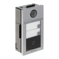
HIKVISION DS-KV8113-WME1 User Manual (50 pages)
Video Intercom Villa Door Station
Brand: HIKVISION
|
Category: Intercom System
|
Size: 2.4 MB
Table of Contents
-
Table of Contents
6
-
1 Appearance
10
-
Single-Button Villa Door Station
10
-
Figure 1, Single-Button Villa Door Station Appearance
10
-
Two-Button Villa Door Station
11
-
Figure 2, Two-Button Villa Door Station Appearance
11
-
Four-Button Villa Door Station
12
-
Figure 3, Four-Button Villa Door Station Appearance
12
-
-
2 Terminal and Wiring Description
13
-
Terminal Description
13
-
Wiring Description
13
-
Door Lock Wiring
13
-
Figure 4, Terminal Description
13
-
Figure 5, Door Lock Wiring
13
-
Door Contact Wiring
14
-
Exit Button Wiring
14
-
Alarm Input Device Wiring
14
-
Figure 6, Door Contact Wiring
14
-
Figure 7, Exit Button Wiring
14
-
-
-
3 Installation
15
-
Accessory Introduction
15
-
Surface Mounting with Protective Shield
15
-
Figure 8, Accessory Introduction
15
-
Surface Mounting Without Protective Shield
16
-
Figure 9, Mounting Template
16
-
Figure 10, Surface Mounting with Protective Shield
16
-
Figure 11, Mounting Template
17
-
Figure 12, Surface Mounting Without Protective Shield
17
-
-
4 Activation
18
-
Activate Device Via Web
18
-
Activate Device Via Client Software
18
-
Edit Network Parameters
19
-
-
5 Remote Configuration Via Web
20
-
Live View
20
-
User Management
20
-
Figure 13, Live View
20
-
Figure 14, User Management
20
-
Device Management
21
-
Parameters Settings
21
-
Figure 15, Device Management
21
-
Figure 16, Local Parameters
22
-
Local Parameters Settings
22
-
Picture and Clip Settings
22
-
Record File Parameters
22
-
Save Record Files to
22
-
-
System Settings
23
-
Figure 17, Online Users
24
-
Figure 18, TCP/IP Settings
25
-
Network Settings TCP/IP Settings
25
-
Port Settings
25
-
Figure 19, Port Settings
26
-
Figure 20, SIP Settings
26
-
SIP Setting
26
-
Figure 21, FTP Settings
27
-
FTP Settings
27
-
Platform Access
27
-
Figure 22, Video Parameters
28
-
Video & Audio Settings Video Parameters
28
-
Audio Parameters
29
-
-
Image Settings
29
-
Display Settings
29
-
Figure 23, Audio Settings
29
-
Figure 24, Display Settings
30
-
Figure 25, Day/Night Mode
30
-
OSD Settings
31
-
Target Cropping
31
-
Figure 26, Backlight
31
-
-
Event Settings
32
-
Motion Detection
32
-
Event Linkage
33
-
Schedule Settings
33
-
-
Intercom Settings
35
-
Device ID Configuration
35
-
Linked Network Settings
35
-
Time Parameters
36
-
-
Ring-Back Tone Settings
36
-
Press Button to Call
36
-
Number Settings
36
-
Access Control Settings Door Parameters
37
-
-
Elevator Control
37
-
-
6 Configuration Via Client Software
39
-
Device Management
39
-
Add Online Device
39
-
Add Device by IP Address
40
-
Add Device by IP Segment
40
-
-
Live View Via Door Station
40
-
Organization Management
40
-
Add Organization
40
-
Modify and Delete Organization
41
-
-
Person Management
41
-
Add Person
41
-
Modify and Delete Person
42
-
Change Person to Other Organization
42
-
Import and Export Person Information
42
-
Get Person Information from Device
43
-
Issue Card in Batch
44
-
Permission Settings
45
-
-
Video Intercom Settings
45
-
Receive Call from Door Station
46
-
Release Notice
46
-
Search Video Intercom Information
47
-
Upload Armed Information
48
-
-
-
Appendix: Communication Matrix and Device Command
49
Advertisement
Advertisement
Related Products
-
HIKVISION DS-KV8102-IM
-
HIKVISION DS-KV8102-IP
-
HIKVISION DS-KV8102-VP
-
HIKVISION DS-KV8102-1A
-
HIKVISION DS-KV8102-1C
-
HIKVISION DS-KV8102-2C
-
HIKVISION DS-KV8103-IMPE2
-
HIKVISION DS-KV8113
-
HIKVISION DS-KV8202-1A
-
HIKVISION DS-KV8213
HIKVISION Categories

Security Camera
DVR
Network Hardware
Intercom System
Security Sensors
More HIKVISION Manuals

Домофоны Hikvision DS-KV8113-WME1 B /Flush УТ-00043544 — инструкция пользователя по применению, эксплуатации и установке на русском языке. Мы надеемся, она поможет вам решить возникшие у вас вопросы при эксплуатации техники.
Вы можете скачать инструкцию к Hikvision DS-KV8113-WME1 B /Flush УТ-00043544 по ссылке ниже, если не хотите ждать загрузки. Если остались вопросы, задайте их в комментариях после инструкции.
«Загружаем инструкцию», означает, что нужно подождать пока файл загрузится и можно будет его читать онлайн. Некоторые инструкции очень большие и время их появления зависит от вашей скорости интернета.
Полезные видео
Характеристики
Остались вопросы?
Не нашли свой ответ в руководстве или возникли другие проблемы? Задайте свой вопрос в форме ниже с подробным описанием вашей ситуации, чтобы другие люди и специалисты смогли дать на него ответ. Если вы знаете как решить проблему другого человека, пожалуйста, подскажите ему


Часто задаваемые вопросы

Как посмотреть инструкцию к Hikvision DS-KV8113-WME1 B /Flush УТ-00043544?
Необходимо подождать полной загрузки инструкции в сером окне на данной странице или скачать кликнув по специальной кнопке.
Руководство на русском языке?
Все наши руководства представлены на русском языке или схематично, поэтому вы без труда сможете разобраться с вашей моделью
Как можно распечатать инструкцию?
Скачайте ее по специальной кнопке над формой чтения на ваше устройства и отправьте на печать.


Код: 204944
В избранное
В сравнение
Функционал: Вызывная видеопанель
Единица измерения: шт
В наличии
Основной склад:
16 990,00 руб Розничная цена
15 291,00 рубОптовая цена
Оставить отзыв
IP вызывная панель на одного абонента с ИК-подсветкой и Wi-Fi, камера 2Мп с углом обзора 129°, встроенный считыватель карт Mifare, 2 реле для замков, PoE, IP65, IK08, 174x91x29 мм
ОСОБЕННОСТИ:
● PoE
● 2 Мп HD-камера
● Подавление шумов и эффекта эхо
● Работает при низком освещении
● Функции контроля доступа
● Датчик контроля вскрытия
● Настройка через веб-интерфейс
● Встроенный Wi-Fi 2.4 ГГц
● Поддержка TF-карт до 128Гб
● Встроенный всенаправленный микрофон
ХАРАКТЕРИСТИКИ:
Флеш-накопитель: 32 MБ
RAM: 256 MБ
Метод работы: Однокнопочная панель
Операционная система : Встроенная ОС Linux
Камера: 2 Мп HD-камера
Угол обзора: По горизонтали: 129°, по вертикали: 75°
Ночное видение: Работает при низком освещении
ИК-подсветка: 3 м
Поддержка функций: BLC, DNR, WDR (True WDR)
Стандарт видеосжатия: H.264
Разрешение: Основной поток 1080p@30 к/с, 720p@25 к/с Дополнительный поток: D1 (704 × 576) @ 25 к/с
Обнаружение движения: Поддерживается
Anti-Flicker, частота: 50 Гц, 60 Гц
Аудиодомофон: Двусторонняя аудиосвязь
Аудиовход: Встроенный всенаправленный микрофон
Аудиовыход: Встроенный динамик
Стандарт аудиосжатия: G.711 U
Скорость потока аудио: 64 Кбит/с
Улучшение качества звука: Подавление шумов и эффекта эхо
Проводная сеть: 10/100 M Ethernet
Сетевой протокол: TCP/IP, RTSP
Считыватель карт, частота считывания: 13.56 МГц
Тип карты: Mifare
Реле: 2 (NO/NC)
RS-485: 1
Wi-Fi: 2.4G Wi-Fi
Служебный порт : 1
TF-карта: макс. 128 ГБ
Тревожный вход: 4
Заземление: 1
Тампер: 1
Физическая кнопка: 1
Уровень защиты: IP65, IK08
Индикатор: 3
Питание: IEEE802.3af, стандартный PoE / DС 12 В
Потребляемая мощность: < 10 Вт
Обогреватель: Поддерживается
Рабочая температура: от -40 до +53 °C
Рабочая влажность: от 10 до 95%
Корпус: алюминиевый сплав
Установка: Накладная установка / врезная установка
Размеры: 174 × 91 × 29 мм
Вызывная видеопанель DS-KV8113-WME1(B) производства компании Hikvision по цене 16 990,00 RUB (15 291,00 RUB для оптовых поставок) с быстрой доставкой по Москве и в любой город России от интернет-магазина Сатро-Паладин. У нас вы можете прочитать подробное описание, посмотреть технические характеристики и перечень необходимых сопутствующих товаров, найти сертификаты и ознакомиться с реальными отзывами покупателей. Не нашли подходящую модель, отправьте заявку на подбор похожих товаров. Мы производим не только поставку, но и монтаж, разработку проекта и сервисное обслуживание.
Функционал
Вызывная видеопанель
Выход управления замком
NC (нормально закрытый)
Выход управления замком
NO (нормально открытый)
Вы можете произвести примерный расчёт доставки на данный товар для розничного магазина (количество принимается равным 1шт.), для более точного расчёта добавьте товар в корзину, расчёт стоимости будет произведён при переходе на страницу корзины. Для клиентов B2B-портала доставка расчитывается менеджером.
- Самовывоз со склада в Москве на Ярославском шоссе
- Курьерская доставка по Москве (только в пределах МКАД)
- Курьерская доставка по Москве (за пределы МКАД)
- Самовывоз из пункта Boxberry (Москва)
- Доставка по России Boxberry
Стоимость доставки: 0 руб.
