
- Manuals
- Brands
- Mitsubishi Electric Manuals
- Inverter
- FR-D740-120-EC
Manuals and User Guides for Mitsubishi Electric FR-D740-120-EC. We have 1 Mitsubishi Electric FR-D740-120-EC manual available for free PDF download: Installation Manuallines
- Manuals
- Brands
- Mitsubishi Electric Manuals
- Inverter
- FR-D740-012
Manuals and User Guides for Mitsubishi Electric FR-D740-012. We have 2 Mitsubishi Electric FR-D740-012 manuals available for free PDF download: Instruction Manual, Installation Manuallines
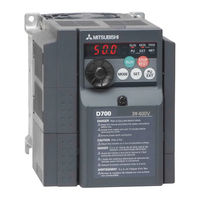
Mitsubishi Electric FR-D740-012 Instruction Manual (296 pages)
Brand: Mitsubishi Electric
|
Category: Inverter
|
Size: 16.8 MB
Table of Contents
-
Instruction Manual
1
-
Table of Contents
5
-
1 Outline
13
-
Product Checking and Parts Identification
13
-
Inverter and Peripheral Devices
14
-
Specifications
14
-
Peripheral Devices
15
-
-
Removal and Reinstallation of the Cover
16
-
Front Cover
16
-
Wiring Cover
18
-
Wiring
18
-
-
Installation of the Inverter and Enclosure Design
19
-
Inverter Installation Environment
19
-
Cooling System Types for Inverter Enclosure
21
-
Inverter Placement
22
-
-
-
2 Wiring
24
-
Terminal Connection Diagram
25
-
Main Circuit Terminal Specifications
26
-
Specification of Main Circuit Terminal
26
-
Terminal Arrangement of the Main Circuit Terminal, Power Supply and the Motor Wiring
26
-
Cables and Wiring Length
28
-
Main Circuit Terminal Specifications
29
-
-
Control Circuit Specifications
31
-
Control Circuit Terminal
31
-
Changing the Control Logic
33
-
Connection of Stand-Alone Option Unit
34
-
Wiring of Control Circuit
35
-
Wiring Instructions
38
-
Connection to the PU Connector
39
-
-
Connection of Stand-Alone Option Unit
41
-
(MRS Type, MYS Type, FR-ABR) (FR-D720-025 or More, FR-D740-012 or More, FR
41
-
Connection of the Brake Unit (FR-BU2)
43
-
Connection of the High Power Factor Converter (FR-HC)
44
-
Connection of the Power Regeneration Common Converter (FR-CV)
45
-
Connection of a DC Reactor (FR-HEL)
45
-
-
-
3 Precautions for Use of the Inverter
46
-
EMC and Leakage Currents
47
-
Leakage Currents and Countermeasures
47
-
Inverter-Driven 400V Class Motor
47
-
EMC Measures
49
-
Power Supply Harmonics
51
-
Installation of Power Factor Improving Reactor
52
-
Power-Off and Magnetic Contactor (MC)
53
-
Inverter-Driven 400V Class Motor
54
-
Precautions for Use of the Inverter
55
-
Failsafe of the System Which Uses the Inverter
57
-
-
4 Parameters
60
-
Operation Panel
61
-
Names and Functions of the Operation Panel
61
-
Basic Operation (Factory Setting)
62
-
Easy Operation Mode Setting (Easy Setting Mode)
63
-
Change the Parameter Setting Value
64
-
Setting Dial Push
64
-
-
Parameter List
65
-
Adjust the Output Torque (Current) of the Motor
75
-
Manual Torque Boost (Pr. 0, Pr. 46)
75
-
Large Starting Torque and Low Speed Torque Are Necessary (General-Purpose Magnetic Flux Vector Control (Pr. 71, Pr. 80))
77
-
Test Run
78
-
Slip Compensation (Pr. 245 to Pr. 247)
80
-
Stall Prevention Operation (Pr. 22, Pr. 23, Pr. 48, Pr. 66, Pr. 156, Pr. 157)
81
-
-
Limit the Output Frequency
85
-
Maximum/Minimum Frequency (Pr. 1, Pr. 2, Pr. 18)
85
-
Avoid Mechanical Resonance Points (Frequency Jumps) (Pr. 31 to Pr. 36)
86
-
-
Set V/F Pattern
87
-
Base Frequency, Voltage (Pr. 3, Pr. 19, Pr. 47)
87
-
Load Pattern Selection (Pr. 14)
89
-
-
Frequency Setting by External Terminals
91
-
Operation by Multi-Speed Operation (Pr. 4 to Pr. 6, Pr. 24 to Pr. 27, Pr. 232 to Pr. 239)
91
-
Jog Operation (Pr. 15, Pr. 16)
93
-
Remote Setting Function (Pr. 59)
95
-
-
Setting of Acceleration/Deceleration Time and Acceleration/ Deceleration Pattern
98
-
Setting of the Acceleration and Deceleration Time (Pr. 7, Pr. 8, Pr. 20, Pr. 44, Pr. 45)
98
-
Starting Frequency and Start-Time Hold Function (Pr. 13, Pr. 571)
100
-
Acceleration/Deceleration Pattern (Pr. 29)
101
-
-
Selection and Protection of a Motor
102
-
Motor Overheat Protection (Electronic Thermal O/L Relay, PTC Thermistor Protection) (Pr. 9, Pr. 51, Pr. 561)
102
-
Applied Motor (Pr. 71, Pr. 450)
105
-
To Exhibit the Best Performance of the Motor (Offline Auto Tuning) (Pr. 71, Pr. 80, Pr. 82 to Pr. 84, Pr. 90, Pr. 96)
107
-
-
Motor Brake and Stop Operation
111
-
DC Injection Brake (Pr. 10 to Pr. 12)
111
-
Selection of a Regenerative Brake (Pr. 30, Pr. 70)
112
-
Stop Selection (Pr. 250)
114
-
-
Function Assignment of External Terminal and Control
115
-
Input Terminal Function Selection (Pr. 178 to Pr. 182)
115
-
Inverter Output Shutoff Signal (MRS Signal, Pr. 17)
117
-
Condition Selection of Function Validity by Second Function Selection Signal (RT)
118
-
Start Signal Operation Selection (STF, STR, STOP Signal, Pr. 250)
119
-
Output Terminal Function Selection (Pr. 190, Pr. 192)
121
-
Detection of Output Frequency (SU, FU Signal, Pr. 41 to Pr. 43)
125
-
Output Current Detection Function (Y12 Signal, Y13 Signal, Pr. 150 to Pr. 153, Pr. 166, Pr. 167)
126
-
Remote Output Selection (REM Signal, Pr. 495, Pr. 496)
128
-
-
Monitor Display and Monitor Output Signal
129
-
Speed Display and Speed Setting (Pr. 37)
129
-
Monitor Display Selection of Operation Panel/Pu and Terminal am (Pr. 52, Pr.158, Pr. 170, Pr. 171, Pr. 268, Pr. 563, Pr. 564, Pr. 891)
130
-
Reference of the Terminal am (Analog Voltage Output) (Pr. 55, Pr. 56)
135
-
Terminal am Calibration (Calibration Parameter C1 (Pr.901))
136
-
-
Operation Selection at Power Failure and Instantaneous Power Failure
138
-
Automatic Restart after Instantaneous Power Failure/Flying Start (Pr. 30, Pr. 57, Pr. 58, Pr. 96, Pr. 162, Pr. 165, Pr. 298, Pr. 299, Pr. 611)
138
-
Power-Failure Deceleration Stop Function (Pr. 261)
144
-
-
Operation Setting at Fault Occurrence
146
-
Retry Function (Pr. 65, Pr. 67 to Pr. 69)
146
-
Input/Output Phase Loss Protection Selection (Pr. 251, Pr. 872)
148
-
-
Earth (Ground) Fault Detection at Start (Pr. 249)
148
-
-
-
Energy Saving Operation
149
-
Optimum Excitation Control (Pr. 60)
149
-
-
Motor Noise, EMI Measures, Mechanical Resonance
150
-
PWM Carrier Frequency and Soft-PWM Control (Pr. 72, Pr. 240, Pr. 260)
150
-
Speed Smoothing Control (Pr. 653)
151
-
-
Frequency Setting by Analog Input (Terminal 2, 4)
152
-
Analog Input Selection (Pr. 73, Pr. 267)
152
-
Response Level of Analog Input and Noise Elimination (Pr. 74)
154
-
Bias and Gain of Frequency Setting Voltage (Current) (Pr. 125, Pr. 126, Pr. 241, C2 (Pr. 902) to C7 (Pr. 905))
155
-
-
Misoperation Prevention and Parameter Setting Restriction
160
-
Reset Selection/Disconnected PU Detection/Pu Stop Selection (Pr. 75)
160
-
Parameter Write Disable Selection (Pr. 77)
163
-
Reverse Rotation Prevention Selection (Pr. 78)
164
-
Extended Parameter Display (Pr. 160)
164
-
Password Function (Pr. 296, Pr. 297)
165
-
-
Selection of Operation Mode and Operation Location
167
-
Operation Mode Selection (Pr. 79)
167
-
Operation Mode at Power-On (Pr. 79, Pr. 340)
177
-
Start Command Source and Frequency Command Source During Communication Operation (Pr. 338, Pr. 339, Pr. 551)
178
-
-
Communication Operation and Setting
182
-
Wiring and Configuration of PU Connector
182
-
Initial Settings and Specifications of RS-485 Communication (Pr. 117 to Pr. 120, Pr. 123, Pr. 124, Pr. 549)
185
-
Operation Selection at Communication Error Occurrence (Pr. 121, Pr. 122, Pr. 502)
186
-
Communication EEPROM Write Selection (Pr. 342)
189
-
Mitsubishi Inverter Protocol (Computer Link Communication)
190
-
Run Command
200
-
Modbus RTU Communication Specifications (Pr. 117, Pr. 118, Pr. 120, Pr. 122, Pr. 343, Pr. 502, Pr. 549)
202
-
-
Special Operation and Frequency Control
214
-
PID Control (Pr. 127 to Pr. 134, Pr. 575 to Pr. 577)
214
-
Dancer Control (Pr. 44, Pr. 45, Pr. 128 to Pr. 134)
222
-
Regeneration Avoidance Function (Pr. 665, Pr. 882, Pr. 883, Pr. 885, Pr. 886)
228
-
-
Useful Functions
230
-
Cooling Fan Operation Selection (Pr. 244)
230
-
Display of the Life of the Inverter Parts (Pr. 255 to Pr. 259)
231
-
Maintenance Timer Alarm (Pr. 503, Pr. 504)
235
-
Current Average Value Monitor Signal (Pr. 555 to Pr. 557)
236
-
Free Parameter (Pr. 888, Pr. 889)
238
-
-
Setting the Parameter Unit and Operation Panel
239
-
RUN Key Rotation Direction Selection (Pr. 40)
239
-
PU Display Language Selection(Pr.145)
239
-
Operation Panel Frequency Setting/Key Lock Operation Selection (Pr. 161)
240
-
Magnitude of Frequency Change Setting (Pr. 295)
242
-
Buzzer Control (Pr. 990)
243
-
PU Contrast Adjustment (Pr. 991)
243
-
-
Parameter Clear/ All Parameter Clear
244
-
Initial Value Change List
245
-
Check and Clear of the Faults History
246
-
-
5 Troubleshooting
249
-
Reset Method of Protective Function
250
-
List of Fault or Alarm Indications
251
-
Causes and Corrective Actions
252
-
Correspondences between Digital and Actual Characters
261
-
Check First When You Have some Troubles
262
-
Motor Does Not Start
262
-
Motor or Machine Is Making Abnormal Acoustic Noise
264
-
Inverter Generates Abnormal Noise
265
-
Motor Generates Heat Abnormally
265
-
Motor Rotates in the Opposite Direction
265
-
Speed Greatly Differs from the Setting
265
-
Acceleration/Deceleration Is Not Smooth
266
-
Speed Varies During Operation
266
-
Operation Mode Is Not Changed Properly
267
-
Operation Panel Display Is Not Operating
267
-
Motor Current Is too Large
267
-
Speed Does Not Accelerate
268
-
Unable to Write Parameter Setting
268
-
-
-
6 Precautions for Maintenance and Inspection
270
-
Inspection Items
270
-
Daily Inspection
270
-
Periodic Inspection
270
-
Daily and Periodic Inspection
271
-
Display of the Life of the Inverter Parts
272
-
Checking the Inverter and Converter Modules
273
-
Cleaning
274
-
Replacement of Parts
274
-
Measurement of Main Circuit Voltages, Currents and Powers
278
-
Measurement of Powers
280
-
Measurement of Voltages and Use of PT
280
-
Measurement of Currents
281
-
Use of CT and Transducer
281
-
Measurement of Inverter Input Power Factor
281
-
Measurement of Converter Output Voltage (Across Terminals P and N)
281
-
Insulation Resistance Test Using Megger
282
-
Pressure Test
282
-
-
-
7 Specifications
283
-
Rating
284
-
Common Specifications
286
-
Outline Dimension Drawings
287
-
-
Appendix
291
-
Appendix1 Index
292
-
-
Advertisement

Mitsubishi Electric FR-D740-012 Installation Manuallines (30 pages)
Brand: Mitsubishi Electric
|
Category: Inverter
|
Size: 2.61 MB
Table of Contents
-
Table of Contents
1
-
Product Checking and Parts Identification
4
-
Outline Dimension Drawings
6
-
Terminal Connection Diagram
7
-
Main Circuit
7
-
Control Circuit
7
-
-
Wiring
7
-
Main Circuit Terminal Specifications
8
-
Cables and Wiring Length
10
-
Control Circuit Specifications
13
-
-
Precautions for Use of the Inverter
15
-
Failsafe of the System Which Uses the Inverter
17
-
Parameter List
18
-
Troubleshooting
22
-
List of Fault or Alarm Indications
23
-
Appendix 2 Instructions for Ul and Cul
27
-
Motor Overload Protection
27
-
Advertisement
Related Products
-
Mitsubishi Electric FR-D740-0.4K
-
Mitsubishi Electric FR-D740-012SC
-
Mitsubishi Electric FR-D740-0.75K
-
Mitsubishi Electric FR-D740-012-EC
-
Mitsubishi Electric FR-D740-022-EC
-
Mitsubishi Electric FR-D740-036-EC
-
Mitsubishi Electric FR-D740-050-EC
-
Mitsubishi Electric FR-D740-080-EC
-
Mitsubishi Electric FR-D740-7.5K-EA
-
Mitsubishi Electric FR-D740-15K
Mitsubishi Electric Categories

Air Conditioner
Controller

Projector
Inverter
Heat Pump
More Mitsubishi Electric Manuals
Серия преобразователей частоты FR-D700 отличается простотой эксплуатации, надежностью и компактными габаритами. Имеют упрощенный электромонтаж благодаря использованию пружинных клемм, встроенный пульт управления с принципиально новой идеологией доступа к параметрам, увеличенный момент в области низких частот вращения, встроенную функцию аварийного отключения и функцию безопасного останова. Основные области применения: насосы, вентиляторы, прессы, конвейеры, промышленные стиральные машины, автоматизированные стеллажные системы и др.
Отличительные особенности:
- Бессенсорное векторное управление
- Высокий вращающий момент на низких частотах вращения
- Функция автоматической настройки параметров
- Функция автоматического рестарта после пропадания питающего напряжения с определением частоты и подхватом свободно вращающегося двигателя
- Интерфейс RS-485, поддерживается протокол Modbus RTU
- Возможность монтажа в шкафу управления вплотную в ряд, без зазоров
- Пульт управления, встроенный в инвертор
- Возможность подключения дополнительных выносных пультов, которые могут быть установлены на удаленной до 15м от ПЧ управляющей панели
- Встроенный тормозной транзистор (от 0,1 кВт до 7,5 кВт)
- Специальные функции встроенной самодиагностики, позволяющие оценить степень износа основных компонентов во время эксплуатации и заранее проинформировать пользователя о необходимости их замены
- Управляемое торможение при кратковременных сбоях в питающей сети
- Функция экономии энергии с применением оптимального возбуждения магнитного потока в двигателе
- Расширенная функция ПИД-регулирования
Дополнительная информация:
 Спецификация FR-D740-120SC-EC скачать. pdf
Инструкция FR-D740-120SC-EC скачать. pdf
Запросить дополнительную информацию и цены