
|
(495) 984-51-05 Москва |
8 800 555 90 55 Вам перезвонить? |
Документация | Преобразователи частоты
FVR Micro 2 Брошюра (рус.)
FVR Micro Спецификация (рус.)
FVR Micro Спецификация (англ.)
Frenic Mini Спецификация (рус.)
Frenic Eco Спецификация (рус.)
Frenic Eco Спецификация (англ.)
Frenic Aqua Руководство пользователя (рус.)
Frenic Aqua Руководство пользователя RS-485 Communication (англ.)
Frenic Multi Спецификация (рус.)
Frenic Mega Спецификация (англ.)
Frenic 5000G11S Спецификация (рус.)
Frenic Mini Каталог (рус.)
Frenic Mini Каталог (англ.)
Frenic Eco Каталог (англ.)
Frenic Multi Каталог (англ.)
Frenic Mega Каталог (англ.)
Frenic 5000G11S Каталог (англ.)
Frenic Ace Каталог (рус.)
Frenic Ace H Каталог (рус.)
Frenic VG (Unit) Каталог (рус.)
Frenic VG (Unit) Каталог (англ.)
Frenic VG (Stack) Каталог (рус.)
Frenic VG (Stack) Каталог (англ.)
Frenic Micro Инструкция по эксплуатации (англ.)
Frenic Mini Инструкция по эксплуатации (рус.)
Frenic Eco Инструкция по эксплуатации (рус.)
Frenic Multi Инструкция по эксплуатации (рус.)
Frenic Mega Инструкция по эксплуатации (рус.)
Frenic Mega Инструкция по эксплуатации (англ.)
Frenic Lift Инструкция по эксплуатации (рус.)
Frenic Lift Инструкция по эксплуатации (англ.)
Frenic Lift LM2 Инструкция по эксплуатации (англ.)
Frenic 5000G11S Инструкция по эксплуатации (рус.)
Frenic Ace Инструкция по эксплуатации (рус.)
Frenic Ace H Инструкция по эксплуатации (англ.)
Frenic VG (Unit) Инструкция по эксплуатации (англ.)
Frenic VG (Stack) Инструкция по эксплуатации (англ.)
Mini/Eco/Multi/Mega Сравнение серий (рус.)
Frenic Eco Многомоторный режим (англ.)
8 (800) 555-90-55info@fuji-drive.ru
|
г. Москва, Семёновский переулок, дом 15, офис 615. +7 (495) 984-51-05 E-mail: info@fuji-drive.ru |
г. Санкт-Петербург, проспект Шаумяна, дом 4, офис 320. +7 (812) 640-46-90 E-mail: info@fuji-drive.ru |
Главная
Корзина
Смотреть корзину.
Каталог продукции
- Преобразователи частоты Fuji Electric
- Высоковольтные преобразователи частоты Fuji Electric
- Сервоприводы Fuji Electric
- Панели оператора Hakko Electronics
- Дополнительные опции Fuji Electric
Запросить документацию
Сертификат

Новости
|
Поддержка и помощь |
Продукция сертифицирована |
Доступность |
Сервисное обслуживание |
Оперативная доставка |
Данный сайт носит информационно-справочный характер и ни при каких условиях не является публичной офертой, которая определяется положениями Статьи 437 (2) Гражданского кодекса РФ.
-
Contents
-
Table of Contents
-
Troubleshooting
-
Bookmarks
Quick Links
STARTING GUIDE
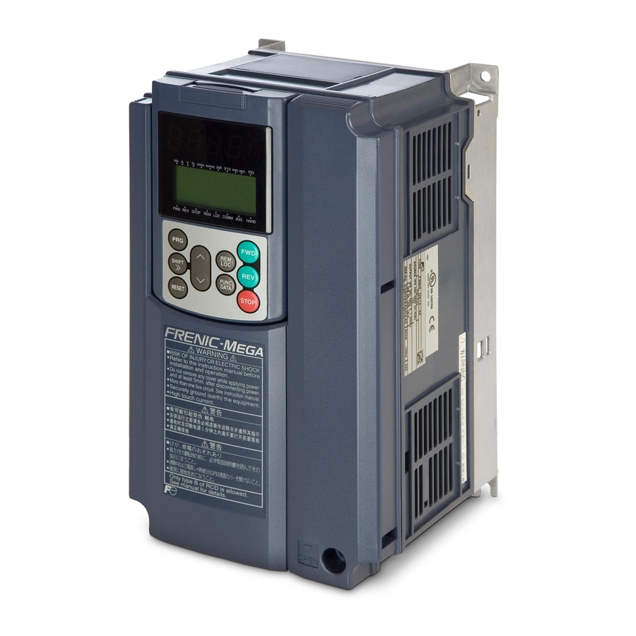
FRENIC MEGA
High Performance Multifunction
Inverter
3 ph 400 V 0.4 to 220 kW
SG_MEGA_EN_1.3.0
Related Manuals for Fuji Electric FRENIC MEGA
Summary of Contents for Fuji Electric FRENIC MEGA
-
Page 1
STARTING GUIDE FRENIC MEGA High Performance Multifunction Inverter 3 ph 400 V 0.4 to 220 kW SG_MEGA_EN_1.3.0… -
Page 2
Index Version Date Applied by 0.4.0 Version for proofreading 16.11.07 Andreas Schader, 0.5.0 European Version 06.02.08 Andreas Schader 0.6.0 Second proofreading 19.02.08 Andreas Schader 0.7.0 Information added and some corrections made, 26.05.08 David Bedford reduced version made Version approved 26.06.08 David Bedford Small corrections in chapter 6 4.06.08… -
Page 3: Table Of Contents
CONTENTS Chapter Page SAFETY INFORMATION AND CONFORMITY TO STANDARDS MOUNTING THE INVERTER WIRING THE INVERTER OPERATION USING THE KEYPAD QUICK START COMMISSIONING FUNCTION CODES TROUBLESHOOTING SPECIFICATIONS AND EXTERNAL DIMENSIONS OPTIONS…
-
Page 4
Preface Thank you for purchasing our FRENIC-Mega series of inverters. This product is designed to drive three-phase induction motors for many types of application. Read through this manual and be familiar with correct handling and operation of this product. Improper handling may result in an incorrect operation, a short life, or even a failure of this product as well as the motor. -
Page 5: Safety Information And Conformity To Standards
Chapter 1 SAFETY INFORMATION AND CONFORMITY TO STANDARDS 1.1 Safety precautions Read this manual thoroughly before proceeding with installation, connections (wiring), operation, or maintenance and inspection. Ensure you have sound knowledge of the device and familiarize yourself with all safety information and precautions before proceeding to operate the inverter. Safety precautions are classified into the following two categories in this manual.
-
Page 6
• Be sure to perform wiring after installing the inverter unit. Otherwise, an electric shock or injuries could occur. • Ensure that the number of input phases and the rated voltage of the product match the number of phases and the voltage of the AC power supply to which the product is to be connected. -
Page 7
EMC directives if an optional EMC compliant filter is connected to them. General purpose inverters are subject to the regulations set forth by the Low Voltage Directive in the EU. Fuji Electric declares the inverters bearing a CE marking are compliant with the Low Voltage Directive. -
Page 8: Mounting The Inverter
Chapter 2 MOUNTING THE INVERTER 2.1 Operating Environment Install the inverter in an environment that satisfies the requirements listed in Table 2.1. Table 2.1 Environmental Requirements Table 2.2 Output Current Derating Factor in Relation to Altitude Item Specifications Output current Altitude Site location Indoors…
-
Page 9
When employing external cooling In external cooling, the heat sink, which dissipates about 70% of the total heat (total loss) generated into air, is situated outside the equipment or the panel. The external cooling, therefore, significantly reduces heat radiating inside the equipment or panel. To employ external cooling for inverters with a capacity of 22 kW or below, use the external cooling attachment option;… -
Page 10: Wiring The Inverter
Chapter 3 WIRING THE INVERTER Follow the procedure below. (In the following description, the inverter has already been installed.) 3.1 Removing and mounting the front cover and the wiring guide (1) For inverters with a capacity of 22 kW or below First loosen the front cover fixing screw, slide the cover downward holding its both sides, tilt it toward you, and then pull it upward, as shown below.
-
Page 11
Table 3.1 Main Circuit Terminal Properties (continued) Power Nominal Terminal Tightening Grounding Tightening HD/LD supply applied motor Inverter type screw torque screw torque Refer to: mode voltage (kW) size (N·m) size (N·m) FRN5.5G1S-4 Figure C FRN7.5G1S-4 FRN11G1S-4 FRN15G1S-4 18.5 FRN18.5G1S-4 Figure D Three- phase… -
Page 12
3.3 Switching connectors The switching connectors are located on the power printed circuit board (power PCB) as shown below. Keypad enclosure Power switching connectors (CN UX) Fan power supply switching connectors (CN R and CN W) Auxiliary fan power input terminals Power PCB Auxiliary power input terminals… -
Page 13
3.4 Wiring of main circuit terminals, grounding terminals and control circuit terminals *1 Install a recommended molded case circuit breaker (MCCB) or residual-current-operated protective device (RCD)/earth leakage circuit breaker (ELCB) (with overcurrent protection function) in the primary circuit of the inverter to protect wiring. Ensure that the circuit breaker capacity is equivalent to or lower than the recommended capacity. *2 Install a magnetic contactor (MC) for each inverter to separate the inverter from the power supply, apart from the MCCB or RCD/ELCB, when necessary. -
Page 14
*9 The connection diagram shows factory default functions assigned to digital input terminals [X1] to [X7], [FWD] and [REV], transistor output terminals [Y1] to [Y4], and relay contact output terminals [Y5A/C] and [30A/B/C]. *10 Switching connectors in the main circuits. For details, refer to » Switching connectors» later in this section. *11 Slide switches on the control printed circuit board (control PCB). -
Page 15
Twist the end of the stripped wires for easy insertion and insert it firmly into the wire inlet on the control circuit terminal. If the insertion is difficult, hold down the clamp release button on the terminal with a flat screwdriver. When disconnecting the wires from the terminal, hold down the clamp release button on the terminal with a flat screwdriver and pull out the wires. -
Page 16
Table 3.3 Symbols, Names and Functions of the Control Circuit Terminals (Continued) Symbol Name Functions — Since low level analog signals are handled, these signals are especially susceptible to the external noise effects. Route the wiring as short as possible (within 20 m) and use shielded wires. In principle, ground the shielded sheath of wires;… -
Page 17
Table 3.3 Symbols, Names and Functions of the Control Circuit Terminals (Continued) Symbol Name Functions (1) Safety stop function that is compliant with EN954-1, Category 3. This terminal allows Enable [EN] the hardware circuit to stop the inverter’s output transistor and coast the motor to a input stop. -
Page 18
Table 3.3 Symbols, Names and Functions of the Control Circuit Terminals (Continued) Symbol Name Functions Programmable Programmable <Control circuit> <Control circuit> logic controller logic controller [PLC] SINK [PLC] SINK SOURCE SOURCE [X1] to [X7], [X1] t o [ X7], Photocoupler Photocoupler [FWD], [REV] [FWD], [REV]… -
Page 19
Table 3.3 Symbols, Names and Functions of the Control Circuit Terminals (Continued) Symbol Name Functions <Control circuit> <Control circuit> Programmable Programmable logic controller logic controller Photocoupler Current Photocoupler Current [Y1] SINK input [Y1] [Y4] [Y4] 31 to 35 V 31 to [CMY] 35 V [CMY]… -
Page 20
3.5 Setting up the slide switches Switching the slide switches located on the control PCB allows you to customize the operation mode of the analog output terminals, digital I/O terminals, and communications ports. The locations of those switches are shown in Figure 3.13. To access the slide switches, remove the front cover so that you can see the control PCB. -
Page 21: Operation Using The Keypad
Chapter 4 OPERATION USING THE KEYPAD LED Monitor, Keys and LED Indicators on the Keypad As shown at the right, the keypad 7-segment consists of a four-digit LED monitor, LED monitor six keys, and five LED indicators. The keypad allows you to run and stop the motor, monitor the running status, UP key indicators…
-
Page 22
4.2 Overview of Operation Modes FRENIC-MEGA features the following three operation modes. Table 4.2 Operation Modes Operation mode Description After powered ON, the inverter automatically enters this mode. This mode allows you to specify the reference frequency, PID command value and etc., and run/stop the motor with the Running mode keys. -
Page 23: Quick Start Commissioning
Chapter 5 QUICK START COMMISSIONING 5.1 Checking prior to powering on Check the following before powering on the inverter. Check that the wiring is correct. Especially check the wiring to the inverter input terminals L1/R, L2/S and L3/T and output terminals U, V, and W. Also check that the grounding wires are connected to the grounding terminals ( G) correctly.
-
Page 24
maximum value allowable in the LD mode. Setting range: Setting range: Motor sound 0.75 to 16 kHz (0.4 to 22 kW) 0.75 to 16 kHz (0.4 to 18.5 kW) (Carrier F 26 0.75 to 16 kHz (30 to 55 kW) 0.75 to 10 kHz (22 to 55 kW) frequency) 0.75 to 10 kHz (75 to 630 kW) -
Page 25
5.5 Function code basic settings for F42=0, 1 or 2 Driving a motor under the V/f control (F42* = 0 or 2) or dynamic torque vector control (F42* = 1) requires configuring the following basic function codes. Configure the function codes listed below according to the motor ratings and your machinery design values. For the motor ratings, check the ratings printed on the motor’s nameplate. -
Page 26
An undervoltage or any other alarm has occurred. If any of these errors occurs, remove the error cause and perform tuning again, or consult your Fuji Electric representative. If an output filter is connected to the inverter’s output (secondary) circuit, the tuning result cannot be assured. When replacing the inverter connected with such a filter, make a note of the old inverter’s settings for the primary resistance %R1, leakage reactance… -
Page 27
Specify motor ratings (the data of P06*, P16* to P23*) by obtaining the appropriate values on the datasheet issued from the motor manufacturer. For details of conversion from data on the datasheet into ones to be entered as function code data, contact your Fuji Electric representative. -
Page 28
3: Enable (when NTC thermistor) Thermistor (for motor) H 26 0: Disable Also turn SW5 on the control printed circuit (Mode selection) board to the PTC/NTC side. Feedback input d 14 2: A/B phase with 90 degree phase shift 2: A/B phase (Pulse train input) Feedback input d 15… -
Page 29
filter and gain that minimize analog input errors. For details, refer to Chapter 6. 5) Calibrating the [FM] output. Calibrate the full scale of the analog meter connected to the terminals [FM1] and [FM2], using the reference voltage equivalent to +10 VDC. To output the reference voltage, it is necessary to select the analog output test with the function code (F31/F35 = 14). -
Page 30: Function Codes
Chapter 6 FUNCTION CODES Function Code Tables Each function code consists of a 3-character alphanumeric string. The first character is a letter that identifies its group and the following two characters are digits that identify each individual code in the group. The function codes are classified into twelve groups: Fundamental Functions (F codes), Extension Terminal Functions (E codes), Control Functions (C codes), Motor 1 Parameters (P codes), High Performance Functions (H codes), Motor 2, 3 and 4 Parameters (A, b and r codes), Application Functions 1 and 2 (J and d codes), Link Functions (y codes) and Option Functions (o codes).
-
Page 31
F37 Load Selection/ 0: Variable torque load Auto Torque Boost/ 1: Constant torque load Auto Energy Saving Operation 1 2: Auto torque boost 3: Auto energy saving (Variable torque load during ACC/DEC) 4: Auto energy saving (Constant torque load during ACC/DEC) 5: Auto energy saving (Auto torque boost during ACC/DEC) F38 Stop Frequency (Detection mode) 0: Detected speed 1: Commanded speed… -
Page 32
72 (1072): Count the run time of commercial power-driven motor 1 (CRUN-M1 ) 73 (1073): Count the run time of commercial power-driven motor 2 (CRUN-M2 ) 74 (1074): Count the run time of commercial power-driven motor 3 (CRUN-M3 ) 75 (1075): Count the run time of commercial power-driven motor 4 (CRUN-M4 ) 76 (1076): Select droop control (DROOP ) 77 (1077): Cancel PG alarm (PG-CCL ) 80 (1080): Cancel customizable logic (CLC ) -
Page 33
111 (1111): Customizable logic output signal 1 (CLO1 ) 112 (1112): Customizable logic output signal 2 (CLO2 ) 113 (1113): Customizable logic output signal 3 (CLO3 ) 114 (1114): Customizable logic output signal 4 (CLO4 ) 115 (1115): Customizable logic output signal 5 (CLO5 ) E30 Frequency Arrival (Hysteresis width) 0.0 to 10.0 Hz E31 Frequency Detection 1 (Level) -
Page 34
C41 Analog Input Adjustment for [V2] (Offset) -5.0% to 5.0% (Gain) 0.00% to 200.00% 100.00 (Filter time constant) 0.00 to 5.00 s 0.05 (Gain base point) 0.00% to 100.00% 100.00 (Polarity) 0: Bipolar 1: Unipolar C50 Bias (Frequency command 1) (Bias base point) 0.00% to 100.00% 0.00 C51 Bias (PID command 1) (Bias Value) -
Page 35
H44 Startup Counter for Motor 1 Indication of cumulative startup count: 0000 to FFFF (hex.) H45 Mock Alarm 0: Disable; 1: Enable (Once a mock alarm occurs, the data automatically returns to 0) H46 Starting Mode (Auto search delay time 2) 0.1 to 10.0 s H47 Initial Capacitance of DC Link Bus Capacitor Indication for replacement of DC link bus capacitor: 0000 to FFFF (hex.) -
Page 36
_14 Drive Control Selection 2, 3, 4 Same as F42 _15 Motor 2, 3, 4 (No. of poles) 2 to 22 poles (Rated capacity) 0.01 to 1000 kW (when b39 = 0, 2, 3 or 4); 0.01 to 1000 HP (when b39 = 1) (Rated current) 0.00 to 2000 A (Auto-tuning) Same as P04 (No-load current) 0.00 to 2000 A… -
Page 37
J68 Brake Signal (Brake-OFF current) 0% to 300% (Brake-OFF frequency/speed) 0.0 to 25.0 Hz (Brake-OFF timer) 0.0 to 5.0 s (Brake-ON frequency/speed) 0.0 to 25.0 Hz (Brake-ON timer) 0.0 to 5.0 s (Brake-OFF torque) 0% to 300% (Speed selection) 0: Detected speed 1: Commanded speed J97 Servo-lock (Gain) 0.00 to 10.00 0.10… -
Page 38
y11 RS-485 Communication (Station address) 1 to 255 (Communications error processing) Same as y02 but y13 applies instead of y03 (Timer) 0.0 to 60.0 s RS-485 Communication 2 (Baud rate) Same as y04 (Data length) 0: 8 bits 1: 7 bits (Parity check) Same as y06 (Stop bits) 0: 2 bits;… -
Page 39
U41 Customizable Logic Step 9 (Input 1) See U01. (Input 2) See U02. (Logic circuit) See U03. (Type of timer) See U04. (Timer) See U05. 0.00 U46 Customizable Logic Step 10 (Input 1) See U01. (Input 2) See U02. (Logic circuit) See U03. (Type of timer) See U04. -
Page 40: Troubleshooting
Chapter 7 TROUBLESHOOTING If any of the protective functions has been activated, first remove the cause. Then, after checking that the all run commands are set to OFF, release the alarm. If the alarm is released while any run commands are set to ON, the inverter may supply the power to the motor, running the motor.
-
Page 41: Specifications And External Dimensions
Chapter 8 SPECIFICATIONS AND EXTERNAL DIMENSIONS 8.1 Standard Model (EMC Filter Built-in Type) 8.1.1 Three-phase 400 V class series (HD- and LD-mode inverters) Item Specifications (FRN G1E-4 ) Type _ _ _ 0.75 18.5 (4.0) 0.75 18.5 Nominal applied motor (4.0) (kW) –…
-
Page 42
8.2 External dimensions (0.4 to 220kW) Chapter 8: Specifications and external dimensions… -
Page 43: Options
Chapter 9 OPTIONS Option name Function and application The DC reactor is used to reduce harmonic components on the input current (mains supply) of the inverter. DC reactor (DCRE) Note: DO NOT FORGET to remove the DC link bar between P1 and P(+) before installing this option.
-
Page 44
CONTACT INFORMATION Headquaters Europe Headquaters Japan Fuji Electric Europe GmbH Fuji Electric Systems Co., Ltd. Goethering 58 Gate City Ohsaki East Tower, 63067 Offenbach/Main 11-2 Osaki 1-chome, Shinagawa-ku, Germany Chuo-ku Tel.: +49 69 669029 0 Tokyo 141-0032 Fax: +49 69 669029 58 Japan info_inverter@fujielectric.de…
|
|
Ремонт частотного преобразователя FUJI
 Ремонт частотного преобразователя frenic от знаменитого производителя Fuji Electric, впрочем, как и ремонт частотников других производителей имеет ряд особенностей в силу своего конструктива. Частотные преобразователи, точнее их начинка делятся на две части:
- Аппаратная часть,
- Программная часть.
Частотники данного производителя не являются исключением из правил, именно поэтому ремонт частотного преобразователя FUJI frenic будет иметь точно такой же ряд особенностей, как и у других преобразователей.
Диагностировать ту или иную неисправность помогают коды ошибок частотного преобразователя, которые отображаются на небольшом дисплее, расположенном на лицевой панели привода. У каждого производителя ПЧ свой набор кодов ошибок выводящиеся на информационную панель частотного преобразователя.
Ремонт частотных преобразователей Fuji, впрочем, как и любых других частотников выпущенных под другими брендами всегда начинается с аппаратной части, после успешного ремонта аппаратной части наступает очередь программной.
Настройка частотного преобразователя frenic прописана в инструкции завода производителя, для каждой серии частотных преобразователей настройка будет индивидуальной, так как каждая линейка преобразователей решает свои собственные задачи, этим обусловливается широкая номенклатура данного промышленного оборудования.
Программирование, настройка частотного преобразователя Fuji frenic
 Настройка частотных преобразователей frenic (программирование) происходит в рамках установленных производителем правил, существует общий алгоритм по программированию (настройке частотных преобразователей), относящийся ко всем производителям данного промышленного оборудования. Ниже представлена пошаговая инструкция по настройке частотных преобразователей Fuji.
- Выбор режима управления приводом frenic (управление по показанию датчиков, дистанционное управление, дистанционное управление).
- В случае использования отдельного (выносного) монитора, настраивается вывод на него технической информации.
- Далее определяем конфигурацию подключения серводвигателя. На данной стадии задаются такие параметры как- возможность применения обратной связи либо без ее применения, а в память блока заносятся данные по: величине крутящего момента, мощности потребителей, номинальное значения частоты, напряжение, ток и скорости вращения ротора.
- Программируется минимально допустимая величина напряжения и частоты, а также время ускорения ротора от ноля до номинального значения.
- И в завершении, в программу управления частотным преобразователем frenic вносятся функциональные данные со значениями отдельных клемм и особенностями сигналов. Отмечаются действия оборудования, выполняющиеся автоматически при отсутствии информации поступающей в оперативном режиме с датчика.
В некоторых преобразователях частоты существует пункт наличия/отсутствия фильтра в цепи питания двигателя. Этот пункт отвечает за подключение различных видов нагрузок, в том случае, когда возможно выбрать нормальное или инверсное изменение частоты при повышении уровня сигнала обратной связи.
Частотный преобразователь Fuji Electric инструкция на русском, скачать
Компания Fuji выпускает восемь основных линеек преобразователей частоты от компактных до общепромышленных:
- FVR Micro (от 0.2 кВт до 2.2 кВт – 220V и от 0.4 кВт до 3.7 кВт – 380V);
- FRENIC Mini FRN-C2 (от 0.1 кВт до 2.2 кВт – 220V и от 2.2 кВт до 15 кВт – 380V);
- FRENIC Multi (от 0.1 кВт до 2.2 кВт – 220V и от 0.4 кВт до 15 кВт – 380V);
- FRENIC Mega (от 0.4 кВт до 630 кВт – 380V);
- FRENIC Eco (от 0.75 кВт до 500 кВт – 380V);
- FRENIC Aqua (от 37 кВт до 90 кВт – 380V);
- FRENIC Lift (от 4 кВт до 45 кВт – 380V);
- FRENIC FRN-G11S-4EN (от 0.4 кВт до 400 кВт – 380V).
Все настройки частотных преобразователей Fuji Electric серии FRENIC приведены в технической документации ниже в удобном формате (PDF) который можно скачать на свой компьютер, распечатать или просто открыть на нашем сайте.
|
Частотный преобразователь Fuji FVR Micro инструкция на руссокм. |
Частотники данного производителя не являются исключением из правил, именно поэтому ремонт частотного преобразователя FUJI frenic будет иметь точно такой же ряд особенностей, как и у других преобразователей. Диагностировать ту или иную неисправность помогают коды ошибок частотного преобразователя, которые отображаются на небольшом дисплее, расположенном на лицевой панели привода. У каждого производителя ПЧ свой набор кодов ошибок выводящиеся на информационную панель частотного преобразователя. Ремонт частотных преобразователей Fuji, впрочем, как и любых других частотников выпущенных под другими брендами всегда начинается с аппаратной части, после успешного ремонта аппаратной части наступает очередь программной. Настройка частотного преобразователя frenic прописана в инструкции завода производителя, для каждой серии частотных преобразователей настройка будет индивидуальной, так как каждая линейка преобразователей решает свои собственные задачи, этим обусловливается широкая номенклатура данного промышленного оборудования. Программирование, настройка частотного преобразователя Fuji frenic
В некоторых преобразователях частоты существует пункт наличия/отсутствия фильтра в цепи питания двигателя. Этот пункт отвечает за подключение различных видов нагрузок, в том случае, когда возможно выбрать нормальное или инверсное изменение частоты при повышении уровня сигнала обратной связи. Частотный преобразователь Fuji Electric инструкция на русском, скачатьКомпания Fuji выпускает восемь основных линеек преобразователей частоты от компактных до общепромышленных:
Все настройки частотных преобразователей Fuji Electric серии FRENIC приведены в технической документации ниже в удобном формате (PDF) который можно скачать на свой компьютер, распечатать или просто открыть на нашем сайте.
Схемы подключения частотных преобразователей Fuji серии FRENICЧастотные преобразователи Fuji имеют довольно широкий спектр применения, от управления небольшими двигателями систем вентиляции (FVR Micro) до грузоподъемных механизмов и промышленных конвейерных линий (FRENIC Mega). Схемы подключений преобразователей частоты отличаются друг от друга в зависимости от модели ПЧ, потребляемой нагрузкой и соответственно схема подключения преобразователя к сети 220V отличается от схемы подключения к промышленной сети 380V. Ниже приведены схемы подключения частотных преобразователей FRENIC Multi и FRENIC Mega
Ремонт частотных преобразователей Fuji в сервисном центреКомпания «Кернел» производит ремонт частотных преобразователей Fuji Electric в с 2002 года. За время существования компании наши сотрудники накопили колоссальный опыт в ремонте преобразователей частоты такого известного производителя как Fuji. Ремонт подобного промышленного оборудования ответственное и сложное занятие, требующие максимальной отдачи, профессионализма и максимально полной материальной базе.
Специалисты нашего сервисного центра максимальное внимание уделяют качеству исполнения ремонта, программирования и настройке промышленных преобразователей частоты, не зависимо от производителя данного промышленного оборудования. Именно поэтому мы смело даем гарантию на все выполненные работы шесть месяцев. Ремонт частотных преобразователей Fuji Electric в производится исключительно с использованием оригинальных запасных частей, на компонентном уровне с применением высокотехнологичного оборудования, квалифицированным персоналом с инженерным образованием. В случае выхода из строя преобразователя частоты на вашем производстве либо появились проблемы с приводом, которые вы не можете решить самостоятельно, мы всегда рады вам помочь. Специалисты нашего сервисного центра в минимальные сроки проведут глубокую диагностику с последующим ремонтом частотного преобразователя Fuji Electric серии FRENIC. Оставьте заказ на ремонт промышленного оборудования используя форму на сайте, либо свяжетесь с нашими менеджерами, сделать это очень просто. Оставить заявку на ремонт частотного преобразователя FUJIУ вас остались вопросы, связанные с ремонтом частотных преобразователей Fuji Electric в ? Оставьте заявку на ремонт нашим менеджерам. Связаться с ними можно несколькими способами:
Далеко не полный список производителей промышленной электроники и оборудования, ремонтируемой в нашей компании.
|
FRN 0.4 G1E-4E, 380~480B (3 ф.), 0.40 кВт / 1.5 A, управл. с ОС, БВУ, динамич. ВК и ВЧХ, IP20, торм. устр-во, ЕМС фильтр
|

| |||||||||||||||||||||||
|
Частотный преобразователь FRENIC Mega схема подключения |
||||||||||||||||||||||||||

|
 Ремонт частотного преобразователя frenic от знаменитого производителя Fuji Electric, впрочем, как и ремонт частотников других производителей имеет ряд особенностей в силу своего конструктива. Частотные преобразователи, точнее их начинка делятся на две части:
Ремонт частотных преобразователей Fuji в сервисном центре
Компания «Кернел» производит ремонт частотных преобразователей Fuji Electric в с 2002 года. За время существования компании наши сотрудники накопили колоссальный опыт в ремонте преобразователей частоты такого известного производителя как Fuji. Ремонт подобного промышленного оборудования ответственное и сложное занятие, требующие максимальной отдачи, профессионализма и максимально полной материальной базе.
 Наш сервисный центр выполняет ремонт всей линейки ПЧ Fuji Electric:
- Ремонт частотного преобразователя FVR Micro;
- Ремонт частотного преобразователя FRENIC Mini FRN-C2;
- Ремонт частотного преобразователя FRENIC Multi;
- Ремонт частотного преобразователя FRENIC Mega;
- Ремонт частотного преобразователя FRENIC Eco;
- Ремонт частотного преобразователя FRENIC Aqua;
- Ремонт частотного преобразователя FRENIC Lift;
- Ремонт частотного преобразователя FRENIC FRN-G11S-4EN.
Специалисты нашего сервисного центра максимальное внимание уделяют качеству исполнения ремонта, программирования и настройке промышленных преобразователей частоты, не зависимо от производителя данного промышленного оборудования. Именно поэтому мы смело даем гарантию на все выполненные работы шесть месяцев.
Ремонт частотных преобразователей Fuji Electric в производится исключительно с использованием оригинальных запасных частей, на компонентном уровне с применением высокотехнологичного оборудования, квалифицированным персоналом с инженерным образованием.
В случае выхода из строя преобразователя частоты на вашем производстве либо появились проблемы с приводом, которые вы не можете решить самостоятельно, мы всегда рады вам помочь. Специалисты нашего сервисного центра в минимальные сроки проведут глубокую диагностику с последующим ремонтом частотного преобразователя Fuji Electric серии FRENIC. Оставьте заказ на ремонт промышленного оборудования используя форму на сайте, либо свяжетесь с нашими менеджерами, сделать это очень просто.
Оставить заявку на ремонт частотного преобразователя FUJI
У вас остались вопросы, связанные с ремонтом частотных преобразователей Fuji Electric в ? Оставьте заявку на ремонт нашим менеджерам. Связаться с ними можно несколькими способами:

- Заказав обратный звонок (кнопка в правом нижнем углу сайта)
- Посредством чата (кнопка расположена с левой стороны сайта)
- Позвонив по номеру телефона:
- +7(8482) 79-78-54;
- +7(8482) 55-96-39;
- +7(917) 121-53-01
- Написав на электронную почту: 89171215301@mail.ru
Далеко не полный список производителей промышленной электроники и оборудования, ремонтируемой в нашей компании.
FRN 0.4 G1E-4E, 380~480B (3 ф.), 0.40 кВт / 1.5 A, управл. с ОС, БВУ, динамич. ВК и ВЧХ, IP20, торм. устр-во, ЕМС фильтр
FRN 0.75 G1E-4E,380~480B (3 ф.), 0.75 кВт / 2.5 A, управл. с ОС, БВУ, динамич. ВК и ВЧХ, IP20, торм. устр-во, ЕМС фильтр
FRN 1.5 G1E-4E, 380~480B (3 ф.), 1.50 кВт / 4.0 A, управл. с ОС, БВУ, динамич. ВК и ВЧХ, IP20, торм. устр-во, ЕМС фильтр
FRN 2.2 G1E-4E, 380~480B (3 ф.), 2.20 кВт / 5.5 A, управл. с ОС, БВУ, динамич. ВК и ВЧХ, IP20, торм. устр-во, ЕМС фильтр
FRN 4.0 G1E-4E, 380~480B (3 ф.), 4.00 кВт / 9.0 A, управл. с ОС, БВУ, динамич. ВК и ВЧХ, IP20, торм. устр-во, ЕМС фильтр
FRN 5.5 G1E-4E, 380~480B (3 ф.), 5.50 кВт / 13.5~16.5 A, управл. с ОС, БВУ, динамич. ВК и ВЧХ, IP20, торм. устр-во, ЕМС фильтр
FRN 7.5 G1E-4E, 380~480B (3 ф.), 7.50 кВт / 18.5~23.0 A, управл. с ОС, БВУ, динамич. ВК и ВЧХ, IP20, торм. устр-во, ЕМС фильтр
FRN 11 G1E-4E, 380~480B (3 ф.), 11.00 кВт / 24.5~30.5 A, управл. с ОС, БВУ, динамич. ВК и ВЧХ, IP20, торм. устр-во, ЕМС фильтр
FRN 15 G1E-4E, 380~480B (3 ф.), 15.00 кВт / 32.0~37.0 A, управл. с ОС, БВУ, динамич. ВК и ВЧХ, IP20, торм. устр-во, ЕМС фильтр
FRN 18.5 G1E-4E,380~480B (3 ф.), 18.50 кВт / 39.0~45.0 A, управл. с ОС, БВУ, динамич. ВК и ВЧХ, IP20, торм. устр-во, ЕМС фильтр
FRN 22 G1E-4E, 380~480B (3 ф.), 22.00 кВт / 45.0~60.0 A, управл. с ОС, БВУ, динамич. ВК и ВЧХ, IP20, торм. устр-во, ЕМС фильтр
FRN 30 G1E-4E, 380~480B (3 ф.), 30.00 кВт / 60.0~75.0 A, управл. с ОС, БВУ, динамич. ВК и ВЧХ, IP20, ЕМС фильтр
FRN 37 G1E-4E, 380~480B (3 ф.), 37.00 кВт / 75.0~91.0 A, управл. с ОС, БВУ, динамич. ВК и ВЧХ, IP20, ЕМС фильтр
FRN 45 G1E-4E, 380~480B (3 ф.), 45.00 кВт / 91.0~112.0 A, управл. с ОС, БВУ, динамич. ВК и ВЧХ, IP20, ЕМС фильтр
FRN 55 G1E-4E, 380~480B (3 ф.), 55.00 кВт / 112.0~150.0 A, управл. с ОС, БВУ, динамич. ВК и ВЧХ, IP20, ЕМС фильтр
FRN 75 G1E-4E, 380~480B (3 ф.), 75.00 кВт / 150.0~176.0 A, управл. с ОС, БВУ, динамич. ВК и ВЧХ, IP20, ЕМС фильтр
FRN 90 G1E-4E, 380~480B (3 ф.), 90 кВт / 176 (210) A, управл. с ОС, БВУ, динамич. ВК и ВЧХ, IP20, ЕМС фильтр
FRN 110 G1E-4E, 380~480B (3 ф.), 110 кВт / 210 (253) A, управл. с ОС, БВУ, динамич. ВК и ВЧХ, IP20, ЕМС фильтр
FRN 132 G1E-4E, 380~480B (3 ф.), 132 кВт / 253 (304) A, управл. с ОС, БВУ, динамич. ВК и ВЧХ, IP20, ЕМС фильтр
FRN 160 G1E-4E, 380~480B (3 ф.), 160 кВт / 304 (377) A, управл. с ОС, БВУ, динамич. ВК и ВЧХ, IP20, ЕМС фильтр
FRN 200 G1E-4E, 380~480B (3 ф.), 200 кВт / 377 (415) A, управл. с ОС, БВУ, динамич. ВК и ВЧХ, IP20, ЕМС фильтр
FRN 220 G1E-4E, 380~480B (3 ф.), 220 кВт / 415 (520) A, управл. с ОС, БВУ, динамич. ВК и ВЧХ, IP20, ЕМС фильтр
FRN 280 G1E-4E, 380~480B (3 ф.), 280 кВт / 520 (650) A, управл. с ОС, БВУ, динамич. ВК и ВЧХ, IP20, ЕМС фильтр
FRN 315 G1E-4E, 380~480B (3 ф.), 315 кВт / 585 (740) A, управл. с ОС, БВУ, динамич. ВК и ВЧХ, IP20, ЕМС фильтр
FRN 355 G1E-4E, 380~480B (3 ф.), 355 кВт / 650 (840) A, управл. с ОС, БВУ, динамич. ВК и ВЧХ, IP20, ЕМС фильтр
FRN 400 G1E-4E, 380~480B (3 ф.), 400 кВт / 740 (960) A, управл. с ОС, БВУ, динамич. ВК и ВЧХ, IP20, ЕМС фильтр
FRN 500 G1E-4E, 380~480B (3 ф.), 500 кВт /960 (1170) A, управл. с ОС, БВУ, динамич. ВК и ВЧХ, IP20, ЕМС фильтр
FRN 630 G1E-4E, 380~480B (3 ф.), 630 кВт/1170 (1370) A, управл. с ОС, БВУ, динамич. ВК и ВЧХ, IP20, ЕМС фильтр
TP-E1U, стандартный пульт управления для серии G1
TP-G1-J1, многофункциональный пульт управления для серии G1

|
(495) 984-51-05 Москва (812) 640-46-90 Санкт-Петербург |
8 800 555 90 55 Вам перезвонить? |
Документация | Преобразователи частоты
FVR Micro 2 Брошюра (рус.)
FVR Micro Спецификация (рус.)
FVR Micro Спецификация (англ.)
Frenic Mini Спецификация (рус.)
Frenic Eco Спецификация (рус.)
Frenic Eco Спецификация (англ.)
Frenic Aqua Руководство пользователя (рус.)
Frenic Aqua Руководство пользователя RS-485 Communication (англ.)
Frenic Multi Спецификация (рус.)
Frenic Mega Спецификация (англ.)
Frenic 5000G11S Спецификация (рус.)
Frenic Mini Каталог (рус.)
Frenic Mini Каталог (англ.)
Frenic Eco Каталог (англ.)
Frenic Multi Каталог (англ.)
Frenic Mega Каталог (англ.)
Frenic 5000G11S Каталог (англ.)
Frenic Ace Каталог (рус.)
Frenic Ace H Каталог (рус.)
Frenic VG (Unit) Каталог (рус.)
Frenic VG (Unit) Каталог (англ.)
Frenic VG (Stack) Каталог (рус.)
Frenic VG (Stack) Каталог (англ.)
Frenic Micro Инструкция по эксплуатации (англ.)
Frenic Mini Инструкция по эксплуатации (рус.)
Frenic Eco Инструкция по эксплуатации (рус.)
Frenic Multi Инструкция по эксплуатации (рус.)
Frenic Mega Инструкция по эксплуатации (рус.)
Frenic Mega Инструкция по эксплуатации (англ.)
Frenic Lift Инструкция по эксплуатации (рус.)
Frenic Lift Инструкция по эксплуатации (англ.)
Frenic Lift LM2 Инструкция по эксплуатации (англ.)
Frenic 5000G11S Инструкция по эксплуатации (рус.)
Frenic Ace Инструкция по эксплуатации (рус.)
Frenic Ace H Инструкция по эксплуатации (англ.)
Frenic VG (Unit) Инструкция по эксплуатации (англ.)
Frenic VG (Stack) Инструкция по эксплуатации (англ.)
Mini/Eco/Multi/Mega Сравнение серий (рус.)
Frenic Eco Многомоторный режим (англ.)
8 (800) 555-90-55info@fuji-drive.ru
|
г. Москва, Семёновский переулок, дом 15, офис 615. +7 (495) 984-51-05 E-mail: info@fuji-drive.ru |
г. Санкт-Петербург, проспект Шаумяна, дом 4, офис 320. +7 (812) 640-46-90 E-mail: info@fuji-drive.ru |
Корзина
Смотреть корзину.
Каталог продукции
- Преобразователи частоты Fuji Electric
- Высоковольтные преобразователи частоты Fuji Electric
- Сервоприводы Fuji Electric
- Панели оператора Hakko Electronics
- Дополнительные опции Fuji Electric
Запросить документацию
Сертификат
Новости
|
Поддержка и помощь |
Продукция сертифицирована |
Доступность |
Сервисное обслуживание |
Оперативная доставка |
Данный сайт носит информационно-справочный характер и ни при каких условиях не является публичной офертой, которая определяется положениями Статьи 437 (2) Гражданского кодекса РФ.
-
Contents
-
Table of Contents
-
Troubleshooting
-
Bookmarks
Quick Links
High-Performance, Low-Noise Inverter
General-Purpose Industrial Machines
230V Series
0.25HP/FRNF25G11S-2UX
to 125HP/FRN125G11S-2UX
460V Series
0.50HP/FRNF50G11S-4UX
to 600HP/FRN600G11S-4UX
Fuji Electric FA Components & Systems Co., Ltd.
Fuji Electric Corp of America
Instruction Manual
FRENIC 5000G11S/P11S
Fans and Pumps
230V Series
7.5HP/FRN007P11S-2UX
to 150HP/FRN150P11S-2UX
460V Series
7.5HP/FRN007P11S-4UX
to 800HP/FRN800P11S-4UX
CAUTION
!
Read all operating instructions before
installing, connecting (wiring),
operating, servicing, or inspecting the
inverter.
Ensure that this instruction manual is
made available to the final user of the
inverter.
Store this manual in a safe,
convenient location.
The product is subject to change
without prior notice.
INR-SI47-1206-E
Summary of Contents for Fuji Electric FRENIC 5000G11S/P11S
Instructions on maintenance, inspection, and replacement
• Wait a minimum of five minutes (30HP or less) or ten minutes (40HP or more) after power has been tumed
off (open) before starting inspection. (Also confirm that the charge lamp is off and that DC voltage between
terminals P (+) and N (-) do not exceed 25V.)
Electrical shock may result.
• Only authorized personnel should perform maintenance, inspection, and replacement operations.(Take off
metal jewelry such as watches and rings. Use insulated tools.)
Electric shock or injury may result.
Instructions on disposal
• Treat as industrial waste when disposing it.
Injury may result.
Other instructions
• Never modify the product.
Electric shock or injury may result.
Conformity to Low Voltage Directive in Europe
• The contact capacity of alarm output for any fault (30A, B, C) and relay signal output (Y5A, Y5C) is 0.5A at
48V DC.
• The ground terminal
Use a crimp terminal to connect a cable to the main circuit terminal or inverter ground terminal.
• Where RCD (Residual-current protective device) is used for protection in case of direct or indirect contact,
only RCD of type B is allowed on the supply side of this EE (Electric equipment).
Otherwise another protective measure shall be applied such as separation of the EE from the environment
by double or reinforced insulation or isolation of EE and supply system by the transformer.
• Use a single cable to connect the
terminals.)
• Use a molded-case circuit breaker (MCCB) and magnetic contactor (MC) that conform to EN or IEC
standards.
• Use the inverter under over-voltage category III conditions and maintain Pollution degree 2 or better as
specified in IEC664. To maintain Pollution degree 2 or more, install the inverter in the control panel (IP54
or higher level) having structure free from water, oil, carbon, dust, etc.
• For the input-output wiring of the inverter, use cable (diameter and type) as specified in Appendix C in
EN60204.
• To ensure safety, install an optional AC reactor, DC reactor, or external braking resistor as follows:
1) Install inside an IP4X cabinet or barrier if electrical parts are exposed.
2) Install inside an IP2X cabinet or barrier if electrical parts are not exposed.
• It is necessary to install the inverter in appropriate method using an appropriate RFI filter to conform to the
EMC directive. It is customer’s responsibility to check whether the equipment, the inverter is installed in,
conforms to EMC directive.
G should be connected to the ground.
G inverter ground terminal. (Do not use two or more inverter ground
WARNING
CAUTION
WARNING
CAUTION
Instruction Manual
FRENIC 5000G11S/P11S
High-Performance, Low-Noise Inverter
General-Purpose Industrial Machines Fans and Pumps
230V Series 230V Series
0.25HP/FRNF25G11S-2UX 7.5HP/FRN007P11S-2UX
to 125HP/FRN125G11S-2UX to 150HP/FRN150P11S-2UX
460V Series 460V Series
0.50HP/FRNF50G11S-4UX 7.5HP/FRN007P11S-4UX
to 600HP/FRN600G11S-4UX to 800HP/FRN800P11S-4UX
!
CAUTION
Read all operating instructions before
installing, connecting (wiring),
operating, servicing, or inspecting the
inverter.
Ensure that this instruction manual is
made available to the final user of the
inverter.
Store this manual in a safe,
convenient location.
The product is subject to change
without prior notice.
Fuji Electric FA Components & Systems Co., Ltd. INR-SI47-1206-E
Fuji Electric Corp of America

Instruction Manual
FRENIC 5000G11S/P11S
High-Performance, Low-Noise Inverter
General-Purpose Industrial Machines
Fans and Pumps
230V Series
230V Series
0.25HP/FRNF25G11S-2UX 7.5HP/FRN007P11S-2UX
to 125HP/FRN125G11S-2UX
to 150HP/FRN150P11S-2UX
460V Series
460V Series
0.50HP/FRNF50G11S-4UX 7.5HP/FRN007P11S-4UX
to 600HP/FRN600G11S-4UX
to 800HP/FRN800P11S-4UX
!
CAUTION
Read all operating instructions before
installing, connecting (wiring),
operating, servicing, or inspecting the
inverter.
Ensure that this instruction manual is
made available to the final user of the
inverter.
Store this manual in a safe,
The product is subject to change
Fuji Electric FA Components & Systems Co., Ltd.
INR-SI47-1206-E
Fuji Electric Corp of America