
-
Contents
-
Table of Contents
-
Bookmarks
Quick Links
INSTRUCTION MANUAL
VHF AIR BAND TRANSCEIVER
iA110
This device complies with Part 15 of the FCC
Rules. Operation is subject to the condition that
this device does not cause harmful interference.
Related Manuals for Icom IC-A110
Summary of Contents for Icom IC-A110
-
Page 1
INSTRUCTION MANUAL VHF AIR BAND TRANSCEIVER iA110 This device complies with Part 15 of the FCC Rules. Operation is subject to the condition that this device does not cause harmful interference. -
Page 2: Foreword
If you experience a ringing in your ears, reduce the struction manual contains important operating instructions for volume level or discontinue use. the IC-A110. R WARNING! NEVER connect the transceiver to an AC outlet or to a power source of more than 27.5 V DC, or EXPLICIT DEFINITIONS use reverse polarity.
-
Page 3: Table Of Contents
■ OPC-871 Headset adapter …………16 ■ Other options …………….17 Icom, Icom Inc. and the Icom logo are registered trademarks of Icom Incor- FOR CLASS B UNINTENTIONAL RADIATORS ……18 porated (Japan) in Japan, the United states, the United Kingdom, Germany, 10 SAFETY TRAINING INFORMATION ……..
-
Page 4: Panel Description
PANEL DESCRIPTION ■ Panel description SCAN q TUNING [DIAL] [TS](DIAL) e VOLUME UP [Y] DOWN [Z] KEY ➥ Changes the operating frequency; memory channel in Adjusts the audio output level. the Memory mode; set mode contents in the Set mode, r LOUD SPEAKER etc.
-
Page 5
PANEL DESCRIPTION y SQL SWITCH [SQL] !0 MICROPHONE CONNECTOR ➥ Push to turn ON the squelch adjust mode. (p. 5) Connects to the supplied microphone or optional. ➥ Hold down this switch for 1 second to turn the both in- NEVER connect other microphones. -
Page 6: Function Display
PANEL DESCRIPTION ■ Function display t TX INDICATOR (p. 4) Appears while transmitting. y FREQUENCY DISPLAY ➥ Shows the operating frequency. (p. 4) ➥ Shows the channel name when the memory name func- tion is selected. (p. 10) u VOLUME LEVEL INDICATORS Shows the AF volume level (while receiving).
-
Page 7: Basic Operation
BASIC OPERATION ■ Power ON ■ Channel selection ï VFO/Memory selection q Push [POWER] to turn ON the power. w Operate the transceiver as described in the following sec- Push [V/M] to select the Mem- tions. ory mode or the VFO mode. ➥…
-
Page 8: Squelch Function
BASIC OPERATION ■ Squelch function ■ Dial select function The transceiver has a noise squelch circuit to mute undesired Use the dial select function to adjust the tuning steps of the noise while receiving no signals. [DIAL] keys. Use 1 MHz tuning when you want to change the frequency in large increments;…
-
Page 9: Scan Operation
SCAN OPERATION • VFO scan ■ Scan operation Repeatedly scans all fre- quencies over the entire q Push [V/M] to select the Memory mode or the VFO mode, lowest highest Start band. if necessary. frequency frequency Scan step is minimum chan- •…
-
Page 10: On-Hook Scan
SCAN OPERATION ■ Dualwatch ■ ON–Hook scan Dualwatch monitors the priority channel while you are receiv- An ON–Hook scan (Hanger scan) stops when taking the mi- ing another channel (VFO or memory channel). crophone off its hanger (OFF–Hook) and resumes when put- ting it back on the hanger (ON–Hook).
-
Page 11: Memory Programming
MEMORY PROGRAMMING ■ Programming a memory channel The transceiver has 99 memory channels for storage of of- D Setting lockout channels ten-used frequencies. In order to speed up the scan periods, you can set memory channels you don’t wish to be scanned as lockout channels. q Push [V/M] to select the VFO mode, if necessary.
-
Page 12: Memory Names
MEMORY PROGRAMMING ■ Memory names ï Programming memory names r Hold down [MW](V/M) for 1 second to input the entered q Select the memory channel to be programmed: name. ➥ Push [V/M] to select the Memory mode. • The character stops blinking. ➥…
-
Page 13: Other Functions
OTHER FUNCTIONS ■ Initial Set mode D Beep tones ON/OFF The Initial Set mode is entered at Power ON and allows you to set seldom-changed settings. In this way you can “custom- Confirmation beep tones normally ize” the transceiver operations to suit your preferences and sound when you push a key.
-
Page 14: Cloning
OTHER FUNCTION ■ Cloning D Priority channel The priority channel is used to store your most often-used D Data cloning channel for quick recall. In addition, the priority channel is Data can be cloned to and from a PC using the optional CS- monitored during priority scan modes.
-
Page 15: Connection And Installation
CONNECTION AND INSTALLATION ■ Rear panel and connections External speaker jack Antenna NOTE: Use the termi- nals as shown for the cable connections. Crimp Solder red: + OPC-871 HEADSET ADAPTER (Option) black: _ Supplied DC power cable RWARNING! NEVER remove the fuse- 12 V or 24 V 12 V or 24 V holders from the DC power cable.
-
Page 16: Mounting
CONNECTION AND INSTALLATION ■ Mounting ■ Supplied accessories Flat washer Spring washer When using self-tapping screws The universal mounting bracket supplied with your trans- q Microphone ���������������������������������������������������������������������������������1 ceiver allows overhead or dashboard mounting. Please read w Microphone hanger and screw set ��������������������������������������� 1 set the following instructions carefully.
-
Page 17: Specifications
SPECIFICATIONS D General D Receiver • Frequency coverage : 118 to 136.975 MHz • Receive system : Double conversion • Channel spacing : 25/8.33 kHz superheterodyne • Mode : AM (6K00A3E/5K6A3E) • Intermediate frequencies : 1st 38.85 MHz • Number of memory channels : 99 450 kHz †…
-
Page 18
SPECIFICATIONS (VFO CHANNEL ID LIST) • Channel spacing: 25 kHz (Actual frequency is displayed.) • Channel spacing: 25/8.33 kHz auto selection mode Operating Frequency Channel spacing Channel ID* Operating Frequency Channel spacing Channel ID* (MHz) (kHz) (Displayed Frequency) (MHz) (kHz) (Displayed Frequency) 118.0000 118.000… -
Page 19: Options
OPTIONS ■ OPC-871 Headset adapter D Installation The optional OPC-871 HEADSET ADAPTER is installed as When using a headset (supplied from 3rd party) with an follows. adapter the transceiver outputs your transmitted voice to the headset for monitoring. (pp. 5, 10) q Turn OFF the power, then disconnect the DC power cable.
-
Page 20: Other Options
Approved Icom optional equipment is designed for optimal perfor- mance when used with an Icom transceiver. Icom is not responsible for the destruction or damage to an Icom transceiver in the event the Icom transceiver is used with equipment Fig. 3…
-
Page 21: For Class B Unintentional Radiators
FOR CLASS B UNINTENTIONAL RADIATORS This equipment has been tested and found to comply with the limits for a Class B digital device, pursuant to part 15 of the FCC Rules. These limits are designed to provide reason- able protection against harmful interference in a residential installation.
-
Page 22: Safety Training Information
During transmissions, your Icom radio generates RF en- to achieve 38 centimeters separation distance. In order ergy that can possibly cause interference with other devices to ensure this distance is met, the installation of the an- or systems.
-
Page 23
2. Il faut que l’antenne émettrice de cet appareil soit placée à l’extérieur d’un véhicule et tenue éloignée d’au moins En mode de transmission, votre radio Icom produit de l’éner- 38 centimètres de toute personne pendant le fonction- gie de RF qui peut provoquer des interférences avec d’autres nement. -
Page 24
A-6940H-1EX-0a Printed in Japan 2011 Icom Inc. © 1-1-32 Kamiminami, Hirano-ku, Osaka 547-0003, Japan Printed on recycled paper with soy ink.

PDF инструкция · 24 страниц(ы) английский
инструкцияICOM IC-A110

iA110
VHF AIR BAND TRANSCEIVER
INSTRUCTION MANUAL
This device complies with Part 15 of the
FCC Rules. Operation is subject to the
condition that this device does not cause
harmful interference.
Посмотреть инструкция для ICOM IC-A110 бесплатно. Руководство относится к категории приемники, 3 человек(а) дали ему среднюю оценку 7.5. Руководство доступно на следующих языках: английский. У вас есть вопрос о ICOM IC-A110 или вам нужна помощь? Задайте свой вопрос здесь

Главная
Не можете найти ответ на свой вопрос в руководстве? Вы можете найти ответ на свой вопрос ниже, в разделе часто задаваемых вопросов о ICOM IC-A110.
Когда звук считается слишком громким?
Могут ли устройства разных марок подключаться друг к другу при помощи Bluetooth?
Как лучше всего выполнять чистку приемник?
Инструкция ICOM IC-A110 доступно в русский?
Не нашли свой вопрос? Задайте свой вопрос здесь
Описание
ВНИМАНИЕ! Радиостанция Icom IC-A110 — СНЯТА С ПРОИЗВОДСТВА! Приобретайте аналог Icom IC-A120
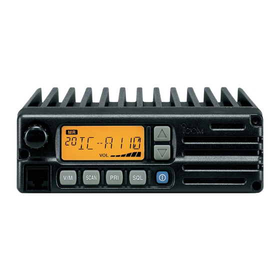
Icom IC-A110 — профессиональная авиационная радиостанция стационарно автомобильного типа для наземных служб. Радиостанция адаптирована для источников питания повышенного напряжения 24 В и может использоваться в составе с шумозащитными авиационными гарнитурами (опция OPC-871). Это надежное средство связи авиационного диапазона соответствует протоколам стандарта защиты от внешних воздействий MIL-STD-810E и рассчитано на повышенные вибрационно-динамические нагрузки.
Краткие технические характеристики радиостанции Icom IC-A24:
Рабочий диапазон частот, МГц: 118.000–136.975
Мощность передатчика, Вт: 36 PEP / 9 несущая
Шаг сетки, кГц: 25 8.33
Кол-во каналов: 20
Тип антенны, разъем на радиостанции: съемная, BNC-мама
Комплект поставки радиостанции Icom IC-A110:
- Радиостанция Icom IC-A110
- HM-161 Тангента, ручной микрофон
- OPC-344 Кабель питания с модулем предохранителей, ±13.8/27.5 В
- Комплект предохранителей, 2 шт., 10 A
- Скоба крепления радиостанции
- Скоба крепления тангенты с кабелем заземления
- Инструкция по эксплуатации Icom IC-A110
Оригинальные аксессуары для радиостанции Icom IC-A110:
- HM-161 Тангента, ручной микрофон
- OPC-871 Кабель-переходник для подключения шумозащитных авиационных аудио-гарнитур
- OPC-344 Кабель питания с модулем предохранителей, ±13.8/27.5 В
- OPC-591 Кабель клонирования
- OPC-592 Адаптер для программирования авиационных радиостанций необходим программатор OPC-478/OPC-478U
- OPC-478 + OPC-592 Кабель для программирования авиационных радиостанций ICOM, RS232 (COM-Port)
- OPC-478U + OPC-592 Кабель для программирования авиационных радиостанций ICOM, USB
- CS-A110 Программное обеспечение для программирования радиостанций ICOM IC-A110
Скачать
iA110
VHF AIR BAND TRANSCEIVER
INSTRUCTION MANUAL
This device complies with Part 15 of the
FCC Rules. Operation is subject to the
condition that this device does not cause
harmful interference.
Инструкция На Icom 110

Радиостанция Icom IC- F110 купить за 9 800 руб. в магазине Ультрател.ру Тел: 8 800 Комплект крепления – 1шт.;; Инструкция – 1шт.;; Упаковка – 1шт.
This service manual describes the latest service informa- tion for the IC- A110 VHF AIR BAND TRANSCEIVER at the time of publication. MODEL. IC- A110.
Краткое описание станции Icom IC- F110. ICOM IC- F110 автомобильная VHF ( 146-174 МГц) Профессиональная возимаяая рация Icom IC- F110.


Icom, Icom Inc. and Icom logo are registered trademarks of Icom In- corporated ( Japan) in Japan, the United States, the United King- dom, Germany, France.
Setting a high standard for ground based communications, the IC- A110 provides durability and reliability in demanding operational environments.

- Разместил: DEN 5.6. Скачать файл: файл pdf ic- a110.pdf (1145.1 Kb). Описание файла. Icom IC- A110 — инструкция на русском языке.
- Разместил: Janissare. Скачать файл: файл pdf icom_ic- f110_manual_rus.pdf ( 1152.4 Kb). Описание файла. Icom IC- F110 — инструкция на.
IC- F110. Прочная конструкция. Литой алюминиевый каркас и передняя панель Service Manual, Инструкция по ремонту с альбомом схем (CD), UT- 111.

Скачать файл: icom_ic-f110_manual_rus.pdf (1152.4 Kb) Описание файла Icom IC-F110 — инструкция на русском языке

IA110. VHF AIR BAND TRANSCEIVER. INSTRUCTION MANUAL. This device expressly approved by Icom Inc., could void your authority to operate this.
Скачать файл: ic-a110.pdf (1145.1 Kb) Описание файла Icom IC-A110 — инструкция на русском языке
Комментарии (8)Просмотров (443)