
-
Contents
-
Table of Contents
-
Bookmarks
Quick Links
INSTRUCTION MANUAL
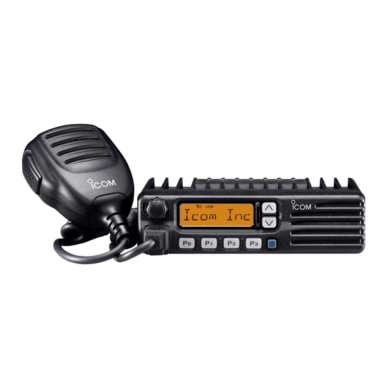
VHF TRANSCEIVER
iF110
UHF TRANSCEIVER
iF210
Related Manuals for Icom IC-F110
Summary of Contents for Icom IC-F110
-
Page 1
INSTRUCTION MANUAL VHF TRANSCEIVER iF110 UHF TRANSCEIVER iF210… -
Page 2: Important
NEVER instruction manual contains important operating instructions connect the transceiver to a power source of more for the IC-F110 VHF TRANSCEIVER and IC-F210 UHF than 16 V DC such as a 24 V battery. This connection will ruin TRANSCEIVER. the transceiver.
-
Page 3: Table Of Contents
I Fuse replacement …………..17 I Cleaning …………….. 17 CAUTION: Changes or modifications to this transceiver, not ex- 5 OPTIONS ………………. 18 pressly approved by Icom Inc., could void your authority to operate 6 CE ………………19–20 this transceiver under FCC regulations.
-
Page 4: Panel Description
PANEL DESCRIPTION I Front panel q AF VOLUME CONTROL KNOB e UP/DOWN [ ] KEYS ➥Push to select the operating channel. Rotate the knob to adjust the audio output level. ➥Can be programmed for one of several functions by your •…
-
Page 5: I Function Display
PANEL DESCRIPTION I Function display t DEALER-PROGRAMMABLE KEYS [P0] to [P3] Desired functions can be programmed independently by your dealer. y MICROPHONE CONNECTOR Connect the supplied microphone or optional DTMF micro- phone for SmarTrunk II operation here. NEVER connect non-specified microphones. The pin assignments may be different and the transceiver may be damaged.
-
Page 6: I Programmable Function Keys
[P3], [ ] and [ ] programmable function keys. Displays the CH number, 5-tone indication, DTMF num- Consult your Icom dealer for details concerning your trans- bers, Audible indication, etc. ceiver’s programming. NOTE: When the alphanumeric display blinks and trans-…
-
Page 7
PANEL DESCRIPTION ¡ ¡ SCAN START/STOP KEY ¡ ¡ MONITOR KEY Push this key to start scanning; and push again Activates one of (or two of) the following functions SCAN A MONI to stop. on each channel independently: SCAN B •… -
Page 8
PANEL DESCRIPTION ¡ ¡ OUTPUT POWER SELECTION KEYS ¡ ¡ CALL KEY Select the transmit output power temporarily, or Transmit a 2-tone, 5-tone code. CALL permanently, depending on the pre-setting. • Call transmission is necessary before you call another station depending on your signaling system. •… -
Page 9
PANEL DESCRIPTION ¡ ¡ SCRAMBLER KEY ¡ ¡ USER SET MODE KEY ➥ Push and hold to turn the voice scrambler func- Changes the contents of the items in the User Set SCRM tion ON. mode. Please refer to p. 10. ➥… -
Page 10: Operation
OPERATION I Turning power ON I Channel selection q Push [ ] to turn the power ON. Several types of channel selection are available. The meth- ods may differ according to your system setup. w If the transceiver is programmed for a start up passcode, input the digit codes as directed by your dealer.
-
Page 11: I Receiving And Transmitting
OPERATION I Receiving and transmitting D Transmitting notes RECEIVING: q Push [ ] to turn the power ON. • Transmit inhibit function w Push [ ] and [ ] to select a channel. The transceiver has several inhibit functions which restrict e When receiving a call, adjust the audio output level to a transmission under the following conditions: comfortable listening level.
-
Page 12: D Tx Code Channel Selection
OPERATION D TX code channel selection D DTMF transmission If the transceiver has a [TX CH] key, the display can be tog- If the transceiver has a [DTMF] key, the automatic DTMF gled between the operating channel number (or name) and transmission function is available.
-
Page 13: D User Set Mode
OPERATION D User set mode User set mode is accessed at power ON and allows you to set seldom-changed settings. In this case you can “cus- tomize” transceiver operation to suit your preferences and operating style. Entering the user set mode: q While pushing and holding [ ] and [ ], push [POWER]…
-
Page 14: Optional Smartrunk
OPTIONAL SmarTrunk II™ OPERATION I SmarTrunk II™ and I SmarTrunk II™ operation conventional modes These features are enabled by a dealer and may not be avail- able in your system. Contact your dealer for details. This transceiver is capable of SmarTrunk II™ functions. D Placing a telephone call The optional UT-105 allows communication in conventional Enter the phone number followed by [1], [M].
-
Page 15: Emergency Call
OPTIONAL SmarTrunk II™ OPERATION D Terminating a call D System busy indication After completing a call, push [#] to disconnect (hang up). If all channels are busy, three low beeps sound after you initi- ate a call. Try the call again later. IMPORTANT!: If one person in the conversation termi- nates a call, all participants will be cut off.
-
Page 16: Connection And Maintenance
CONNECTION AND MAINTENANCE I Rear panel and connection Optional speaker Antenna (SP-22) R C A U T I O N ! N E V E R r e- red: move the fuse-holder from the DC power cable. NOTE: Use the terminals as shown below for the cable connections.
-
Page 17: I Supplied Accessories
CONNECTION AND MAINTENANCE I Supplied Accessories q ANTENNA CONNECTOR Connects to an antenna. Contact your dealer about an- tenna selection and placement. w MICROPHONE HANGER Connect the supplied microphone hanger to the vehicle’s KEY-STICKER ground for microphone on/off hook functions. (See p. 2) e DC POWER RECEPTACLE Connects to a 12 V DC battery.
-
Page 18: I Mounting The Transceiver
CONNECTION AND MAINTENANCE I Mounting the transceiver I Optional UT-105, UT-108 or UT-111 installation The universal mounting bracket supplied with your transceiv- er allows overhead mounting. Install the optional UT-105, UT-108 or UT-111 unit as follows: • Mount the transceiver securely with the 4 supplied screws q Turn the power OFF, then disconnect the DC power cable.
-
Page 19: I Optional Ut-109 Or Ut-110 Installation
CONNECTION AND MAINTENANCE I Optional UT-109 or UT-110 I Optional OPC-617 installation installation Install the OPC-617 as shown below. q Turn the power OFF, then disconnect the DC power cable. w Unscrew the 4 cover screws, then remove the bottom cover.
-
Page 20: I Antenna
CONNECTION AND MAINTENANCE I Antenna A key element in the performance of any communication sys- tem is an antenna. Contact your dealer about antennas and the best places to mount them. I Fuse replacement A fuse is installed in the supplied DC power cable. If a fuse blows or the transceiver stops functioning, track down the source of the problem if possible, and replace the damaged fuse with a new rated one.
-
Page 21: Options
OPTIONS SP-22 EXTERNAL SPEAKER Compact and easy-to-install. Input impedance : 4 Ω Max. input power : 5 W HM-100TN DTMF microphone. SM-25 Desktop microphone. UT-105 SmarTrunk II Logic Board Provides SmarTrunk II capabilities. UT-108 DTMF DECODER UNIT Provides pager and code squelch capabilities. UT-109/UT-110 (#02) VOICE SCRAMBLER UNIT •…
-
Page 22
DECLARATION OF CONFORMITY We Icom Inc. Japan 0168 1-1-32, Kamiminami, Hirano-ku Osaka 547-0003, Japan Declare on our sole responsibility that this equipment complies with the essential requirements of the Radio and Telecommunications Terminal Equipment Directive, 1999/5/EC, and that any applicable Essential Test Düsseldorf 18th Nov. -
Page 23
EN 60950 (August 1992 +A11) iv) EN 300 086-2 (March 2001) Signature v) EN 300 219-2 (March 2001) About e-marking: Detailed installation notes for Icom mobile transceivers to be fitted into vehicles are available. Please contact your Icom dealer or distributor. -
Page 24
< Intended Country of Use > A-6234H-1EU-q Printed in Japan 1-1-32 Kamiminami, Hirano-ku, Osaka 547-0003 Japan © 2002–2003 Icom Inc.
This manual is also suitable for:
Ic-f210
Хорошее руководство по эксплуатации
Законодательство обязывает продавца передать покупателю, вместе с товаром, руководство по эксплуатации Icom IC-F110. Отсутствие инструкции либо неправильная информация, переданная потребителю, составляют основание для рекламации в связи с несоответствием устройства с договором. В законодательстве допускается предоставлении руководства в другой, чем бумажная форме, что, в последнее время, часто используется, предоставляя графическую или электронную форму инструкции Icom IC-F110 или обучающее видео для пользователей. Условием остается четкая и понятная форма.
Что такое руководство?
Слово происходит от латинского «instructio», тоесть привести в порядок. Следовательно в инструкции Icom IC-F110 можно найти описание этапов поведения. Цель инструкции заключается в облегчении запуска, использования оборудования либо выполнения определенной деятельности. Инструкция является набором информации о предмете/услуге, подсказкой.
К сожалению немного пользователей находит время для чтения инструкций Icom IC-F110, и хорошая инструкция позволяет не только узнать ряд дополнительных функций приобретенного устройства, но и позволяет избежать возникновения большинства поломок.
Из чего должно состоять идеальное руководство по эксплуатации?
Прежде всего в инструкции Icom IC-F110 должна находится:
— информация относительно технических данных устройства Icom IC-F110
— название производителя и год производства оборудования Icom IC-F110
— правила обслуживания, настройки и ухода за оборудованием Icom IC-F110
— знаки безопасности и сертификаты, подтверждающие соответствие стандартам
Почему мы не читаем инструкций?
Как правило из-за нехватки времени и уверенности в отдельных функциональностях приобретенных устройств. К сожалению само подсоединение и запуск Icom IC-F110 это слишком мало. Инструкция заключает ряд отдельных указаний, касающихся функциональности, принципов безопасности, способов ухода (даже то, какие средства стоит использовать), возможных поломок Icom IC-F110 и способов решения проблем, возникающих во время использования. И наконец то, в инструкции можно найти адресные данные сайта Icom, в случае отсутствия эффективности предлагаемых решений. Сейчас очень большой популярностью пользуются инструкции в форме интересных анимаций или видео материалов, которое лучше, чем брошюра воспринимаются пользователем. Такой вид инструкции позволяет пользователю просмотреть весь фильм, не пропуская спецификацию и сложные технические описания Icom IC-F110, как это часто бывает в случае бумажной версии.
Почему стоит читать инструкции?
Прежде всего здесь мы найдем ответы касательно конструкции, возможностей устройства Icom IC-F110, использования отдельных аксессуаров и ряд информации, позволяющей вполне использовать все функции и упрощения.
После удачной покупки оборудования/устройства стоит посвятить несколько минут для ознакомления с каждой частью инструкции Icom IC-F110. Сейчас их старательно готовят или переводят, чтобы они были не только понятными для пользователя, но и чтобы выполняли свою основную информационно-поддерживающую функцию.
Содержание руководства
| Файл PDF (рус.) | 150 руб |
VHF трансивер Icom IC-F110
Инструкция по эксплуатации VHF трансивера на русском языке.
Диапазон частот: 136-174 МГц
Выходная ВЧ мощность: 25 Вт.
Характеристики инструкции
-
Язык инструкции:
Русский -
Формат документа:
PDF -
Объём документа:
10 стр.
← Icom IC-F110S
Alinco DR-M06R →
Краткое содержание страницы № 1
IC-F110_F210_GEN.qxd 02.12.11 4:25 PM Page a (1,1)
INSTRUCTION MANUAL
VHF TRANSCEIVER
iF110
UHF TRANSCEIVER
iF210
Краткое содержание страницы № 2
IC-F110_F210_GEN.qxd 02.12.11 4:25 PM Page i (1,1) IMPORTANT PRECAUTION READ ALL INSTRUCTIONS carefully and com- RWARNING! NEVER connect the transceiver to an pletely before using the transceiver. AC outlet. This may pose a fire hazard or result in an electric shock. SAVE THIS INSTRUCTION MANUAL— This instruction manual contains important operating instructions NEVER connect the transceiver to a power source of more for the IC-F110 VHF TRANSCEIVER and IC-F210 UHF than 16 V DC such as a 24 V bat
Краткое содержание страницы № 3
IC-F110_F210_GEN.qxd 02.12.11 4:25 PM Page ii (1,1) TABLE OF CONTENTS IMPORTANT ………………………………………………………………………… i DO NOT use or place the transceiver in areas with tem- EXPLICITDEFINITIONS ……………………………………………………….. i peratures below –30°C (–22°F) or above +60°C (+140°F), or PRECAUTION ………………………………………………………………………. i TABLE OF CONTENTS …………….
Краткое содержание страницы № 4
IC-F110_F210_GEN.qxd 02.12.11 4:25 PM Page 1 (1,1) PANEL DESCRIPTION 1 Front panel q w e y t r qAF VOLUME CONTROL KNOB eUP/DOWN [ ]/[ ] KEYS Rotate the knob to adjust the audio output level. ➥Push to select the operating channel. • Minimum audio level is pre-programmed. ➥Can be programmed for one of several functions by your dealer. (Same as [P0] to [P3] keys) wFUNCTION DISPLAY Displays a variety of information, such as an operating rPOWER SWITCH [POWER] channel number/name, 5-tone code, DTM
Краткое содержание страницы № 5
IC-F110_F210_GEN.qxd 02.12.11 4:25 PM Page 2 (1,1) PANEL DESCRIPTION 1 tDEALER-PROGRAMMABLE KEYS [P0] to [P3] Function display Desired functions can be programmed independently by your dealer. q w e r t y u yMICROPHONE CONNECTOR Connect the supplied microphone or optional DTMF micro- TM i phone for SmarTrunk II operation here. NEVER connect non-specified microphones. The pin assignments may be different and the transceiver may be damaged. qTRANSMIT INDICATOR Appears while transmitting. D D M
Краткое содержание страницы № 6
IC-F110_F210_GEN.qxd 02.12.11 4:25 PM Page 3 (1,1) 1 PANEL DESCRIPTION u2/5TONE INDICATOR Programmable function keys Appears when the specified 2/5-tone call is received. The following functions can be assigned to [P0], [P1], [P2], i ALPHANUMERIC DISPLAY [P3], [ ] and [] programmable function keys. Displays the CH number, 5-tone indication, DTMF num- Consult your Icom dealer for details concerning your trans- bers, Audible indication, etc. ceiver’s programming. NOTE: When the alphanumeric disp
Краткое содержание страницы № 7
IC-F110_F210_GEN.qxd 02.12.11 4:25 PM Page 4 (1,1) PANEL DESCRIPTION 1 ¡ ¡ SCAN START/STOP KEY ¡ ¡ MONITOR KEY Push this key to start scanning; and push again Activates one of (or two of) the following functions SCAN A MONI to stop. on each channel independently: SCAN B • Push and hold the key to unmute the channel (audio NOTE: Place the microphone on hook to start is emitted; ‘Audible’ condition). scanning. • Push the key to toggle between the mute and unmute Take the microphone off hook to s
Краткое содержание страницы № 8
IC-F110_F210_GEN.qxd 02.12.11 4:25 PM Page 5 (1,1) 1 PANEL DESCRIPTION ¡ ¡ OUTPUT POWER SELECTION KEYS ¡ ¡ CALL KEY Select the transmit output power temporarily, or Transmit a 2-tone, 5-tone code. H/L CALL • Call transmission is necessary before you call another permanently, depending on the pre-setting. station depending on your signaling system. • Contact your dealer for the output power level for each CAL A • The [CAL A] and/or [CAL B] keys may be available selection. when your system emplo
Краткое содержание страницы № 9
IC-F110_F210_GEN.qxd 02.12.11 4:25 PM Page 6 (1,1) PANEL DESCRIPTION 1 ¡ ¡ SCRAMBLER KEY ¡ ¡ USER SET MODE KEY ➥ Push and hold to turn the voice scrambler func- Changes the contents of the items in the User Set SCRM SET tion ON. mode. Please refer to p. 10. • Push and hold this key for 1 sec. to enter set mode. ➥ Push this key to turn the voice scrambler func- Push this key again momentarily to select the desired tion OFF. item. Push []/[] to set the desired level/condi- tion. NOTE: Push and h
Краткое содержание страницы № 10
IC-F110_F210_GEN.qxd 02.12.11 4:25 PM Page 7 (1,1) OPERATION 2 Turning power ON Channel selection q Push [ ] to turn the power ON. Several types of channel selection are available. The meth- ods may differ according to your system setup. w If the transceiver is programmed for a start up passcode, input the digit codes as directed by your dealer. NON-BANK TYPE: • The keys in the table below can be used for password input: Push []/[] to select the desired operating channel in • The transceiver
Краткое содержание страницы № 11
IC-F110_F210_GEN.qxd 02.12.11 4:25 PM Page 8 (1,1) OPERATION 2 Receiving and transmitting RECEIVING: DTransmitting notes q Push [ ] to turn the power ON. • Transmit inhibit function w Push [] and [] to select a channel. The transceiver has several inhibit functions which restrict e When receiving a call, adjust the audio output level to a transmission under the following conditions: comfortable listening level. — The channel is in mute condition (‘Inaudible’ condition; “ ” does not appear). T
Краткое содержание страницы № 12
IC-F110_F210_GEN.qxd 02.12.11 4:25 PM Page 9 (1,1) 2 OPERATION DTX code channel selection DDTMF transmission If the transceiver has a [TX CH] key, the display can be tog- If the transceiver has a [DTMF] key, the automatic DTMF gled between the operating channel number (or name) and transmission function is available. Up to 7 DTMF channels TX code channel number (or name). When the TX code may be available. channel number (or name) is displayed, the []/[] keys select the TX code channel. To tra
Краткое содержание страницы № 13
IC-F110_F210_GEN.qxd 02.12.11 4:25 PM Page 10 (1,1) OPERATION 2 DUser set mode User set mode is accessed at power ON and allows you to set seldom-changed settings. In this case you can “cus- tomize” transceiver operation to suit your preferences and operating style. Entering the user set mode: q While pushing and holding[] and [], push [POWER] to enter user set mode ON, allowing you to set seldom- changed settings. w Push and hold [P0] to select the appropriate item. Then, push [] or [] to set
Краткое содержание страницы № 14
IC-F110_F210_GEN.qxd 02.12.11 4:25 PM Page 11 (1,1) OPTIONAL SmarTrunk II™ OPERATION 3 SmarTrunk II™ and SmarTrunk II™ operation conventional modes These features are enabled by a dealer and may not be avail- able in your system. Contact your dealer for details. This transceiver is capable of SmarTrunk II™ functions. DPlacing a telephone call The optional UT-105 allows communication in conventional Enter the phone number followed by [1], [M]. channels or SmarTrunk II™ channels. Select a chan
Краткое содержание страницы № 15
IC-F110_F210_GEN.qxd 02.12.11 4:25 PM Page 12 (1,1) OPTIONAL SmarTrunk II™ OPERATION 3 DTerminating a call DSystem busy indication After completing a call, push [#] to disconnect (hang up). If all channels are busy, three low beeps sound after you initi- ate a call. Try the call again later. IMPORTANT!: If one person in the conversation termi- nates a call, all participants will be cut off. DPTT dispatch operation q Push [PTT] once (without dialling) to initiate a dispatch call. DLast number r
Краткое содержание страницы № 16
IC-F110_F210_GEN.qxd 02.12.11 4:25 PM Page 13 (1,1) CONNECTION AND MAINTENANCE 4 Rear panel and connection w Optional speaker Antenna (SP-22) R CAUTION! NEVER re- q red: + move the fuse-holder from the DC power cable. NOTE: Use the terminals as t shown below for the cable connections. 12V Crimp Optional cable Battery Solder (OPC-617) e NEVER connect to a 24 V battery. black: r 13
Краткое содержание страницы № 17
IC-F110_F210_GEN.qxd 02.12.11 4:25 PM Page 14 (1,1) CONNECTION AND MAINTENANCE 4 q ANTENNA CONNECTOR Supplied Accessories Connects to an antenna. Contact your dealer about an- tenna selection and placement. qw e r t w MICROPHONE HANGER KEY-STICKER Connect the supplied microphone hanger to the vehicle’s ground for microphone on/off hook functions. (See p. 2) y u e DC POWER RECEPTACLE Connects to a 12 V DC battery. Pay attention to polarities. i NEVER connect to a 24 V battery. This could dama
Краткое содержание страницы № 18
IC-F110_F210_GEN.qxd 02.12.11 4:25 PM Page 15 (1,1) 4 CONNECTION AND MAINTENANCE Mounting the transceiver Optional UT-105, UT-108 or The universal mounting bracket supplied with your transceiv- UT-111 installation er allows overhead mounting. Install the optional UT-105, UT-108 or UT-111 unit as follows: •Mount the transceiver securely with the 4 supplied screws to a thick surface which can support more than 1.5 kg. q Turn the power OFF, then disconnect the DC power cable. w Unscrew the 4 c
Краткое содержание страницы № 19
IC-F110_F210_GEN.qxd 02.12.11 4:25 PM Page 16 (1,1) CONNECTION AND MAINTENANCE 4 Optional UT-109 or UT-110 Optional OPC-617 installation Install the OPC-617 as shown below. installation q Turn the power OFF, then disconnect the DC power cable. w Unscrew the 4 cover screws, then remove the bottom cover. e Cut the pattern on the PCB at the TX mic circuit (MIC) and RX AF circuit (DISC) as shown below. r Install the scrambler unit as described in the installation of optional UT-105, UT-108 or
Краткое содержание страницы № 20
IC-F110_F210_GEN.qxd 02.12.11 4:25 PM Page 17 (1,1) 4 CONNECTION AND MAINTENANCE Antenna A key element in the performance of any communication sys- tem is an antenna. Contact your dealer about antennas and the best places to mount them. Fuse replacement A fuse is installed in the supplied DC power cable. If a fuse blows or the transceiver stops functioning, track down the source of the problem if possible, and replace the damaged fuse with a new rated one. ❑Fuse rating: 10 A, IC-F520/F620: