
- Manuals
- Brands
- JUMO Manuals
- Controller
- dTRON 308
Manuals and User Guides for JUMO dTRON 308. We have 3 JUMO dTRON 308 manuals available for free PDF download: Operating Manual, Operating Instructions Manual
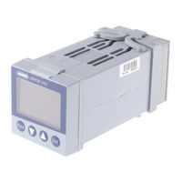
JUMO dTRON 308 Operating Manual (78 pages)
compact controller with program function
Brand: JUMO
|
Category: Controller
|
Size: 2 MB
Table of Contents
-
Table of Contents
3
-
1 Introduction
7
-
Description
7
-
Typographical Conventions
8
-
-
2 Identifying the Instrument Version
9
-
Type Designation
9
-
Scope of Delivery
10
-
Accessories
10
-
-
3 Mounting
11
-
Mounting Site and Climatic Conditions
11
-
Dimensions
11
-
Type 703044
11
-
Type 703042/43
12
-
Type 703041
12
-
Side-By-Side Mounting
13
-
Fitting in Position
13
-
Removing the Controller Module
14
-
-
4 Electrical Connection
15
-
Installation Notes
15
-
Electrical Isolation
16
-
Connection Diagrams
17
-
Type 703041
17
-
Type 703042/43/44
20
-
Termination Resistor for the RS422/485 Serial Interface
24
-
Connection of the PROFIBUS-DP Connector
24
-
-
5 Operation
25
-
Displays and Controls
25
-
Level Concept
26
-
Level Inhibit
27
-
Entries and Operator Prompting
28
-
Fixed-Setpoint Controller (Ex-Factory)
29
-
Program Controller
30
-
Entering Programs
30
-
Operation
32
-
Shifting the Program Profile
33
-
-
6 Operator Level
35
-
7 Parameter Level
37
-
8 Configuration
39
-
Analog Inputs «Inp
41
-
Customized Fine Tuning
43
-
Controller «Cntr
45
-
Generator «Pro
47
-
Limit Comparators «LC
50
-
Outputs «Outp
54
-
Binary Functions «Binf
56
-
Display «Disp
59
-
Timer «Tfct
61
-
Interfaces «Intf
62
-
-
9 Tuning (Optimization)
63
-
Autotuning (Self-Optimization)
63
-
Check of the Tuning
66
-
-
10 Extra Codes
67
-
Math and Logic Module
67
-
Difference, Humidity or Ratio Controller
67
-
-
11 Retrofitting of Modules
69
-
12 Appendix
71
-
Alarm Messages
74
-
-
13 Index
75
Advertisement
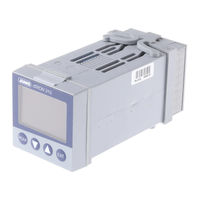
JUMO dTRON 308 Operating Manual (78 pages)
Compact Controller with program function
Brand: JUMO
|
Category: Controller
|
Size: 1.73 MB
Table of Contents
-
Table of Contents
3
-
Introduction
7
-
Description
7
-
Typographical Conventions
8
-
Identifying the Instrument Version
9
-
Type Designation
9
-
Scope of Delivery
10
-
Accessories
10
-
Mounting
11
-
Mounting Site and Climatic Conditions
11
-
Dimensions
11
-
Type 703044
11
-
Type 703042/43
12
-
Type 703041
12
-
Side-By-Side Mounting
13
-
Fitting in Position
13
-
Removing the Controller Module
14
-
Electrical Connection
15
-
Installation Notes
15
-
Electrical Isolation
16
-
Connection Diagrams
17
-
Type 703041
17
-
Type 703042/43/44
20
-
Termination Resistor for the RS422/485 Serial Interface
24
-
Connection of the PROFIBUS-DP Connector
24
-
Operation
25
-
Displays and Controls
25
-
Level Concept
26
-
Level Inhibit
27
-
Entries and Operator Prompting
28
-
Fixed-Setpoint Controller (Ex-Factory)
29
-
Program Controller
30
-
Entering Programs
30
-
Operation
32
-
Shifting the Program Profile
33
-
Operator Level
35
-
Parameter Level
37
-
Configuration
39
-
Analog Inputs «Inp
41
-
Customized Fine Tuning
43
-
Controller «Cntr
45
-
Generator «Pro
47
-
Limit Comparators «LC
50
-
Outputs «Outp
54
-
Binary Functions «Binf
56
-
Display «Disp
59
-
Timer «Tfct
61
-
Interfaces «Intf
62
-
Tuning (Optimization)
63
-
Autotuning (Self-Optimization)
63
-
Check of the Tuning
66
-
Extra Codes
67
-
Math and Logic Module
67
-
Difference, Humidity or Ratio Controller
67
-
Retrofitting of Modules
69
-
Appendix
71
-
Alarm Messages
74
-
Index
75
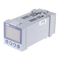
JUMO dTRON 308 Operating Instructions Manual (24 pages)
Compact Controller with program function
Brand: JUMO
|
Category: Controller
|
Size: 0.83 MB
Table of Contents
-
Table of Contents
3
-
1 Preface
4
-
Scope of Delivery
4
-
-
2 Identifying the Instrument Version
5
-
3 Mounting
6
-
Preparation
6
-
Fitting in Position, Type 703042/43/44
6
-
Fitting in Position, Type 703041
6
-
-
4 Electrical Connection
7
-
Connection Diagram for Type 703041
7
-
Connection Diagram for Type 703042/43/44
8
-
-
5 Displays and Keys
9
-
6 Operation
10
-
Level Concept
10
-
Level Inhibit
11
-
Entering Values
11
-
Entering Times
12
-
Operation of the Fixed-Setpoint Controller
13
-
Operation of the Program Controller
14
-
-
7 Operator Level «Opr
15
-
8 Parameter Level «Para
16
-
9 Configuration Level «Conf
17
-
Analog Inputs «Inp
17
-
Controller «Cntr
18
-
Generator «Pro
18
-
Outputs «Outp
19
-
Display «Disp
20
-
-
10 Autotuning
21
-
11 Alarms
22
Advertisement
Advertisement
Related Products
-
JUMO dTRON 304
-
JUMO dTRON 316
-
Jumo dTRON 314
-
JUMO dTRON16.1
-
JUMO DICON 501
-
JUMO diraVIEW 108
-
JUMO DICON 400
-
JUMO DICON 500
-
JUMO diraVIEW 116
-
JUMO diraVIEW 132
JUMO Categories
Transmitter
Measuring Instruments
Controller
Thermostat
Voice Recorder
More JUMO Manuals

Серия регуляторов JUMO dTRON 300 включает в себя четыре свободно программируемых прибора с различными форматами по DIN для регулирования температуры, давления и других переменных процесса. Жидкокристаллический высококонтрастный многоцветный экран для отображения действительного и заданного значений, а также комментариев оператора, содержит два четырехразрядных 7-сегментных дисплея, два одноразрядных 16-сегментных дисплея, дисплей для отображения текущего заданного значения, шесть индикаторов переключения положения и индикаторы для отображения единицы измерения, функции рампы и режима ручного управления.
Управление прибором осуществляется с помощью четырех кнопок.
Приборы могут работать как 2-позиционные, 3-прозиционные, 3-прозиционные шаговые или непрерывные регуляторы. Программное обеспечение предусматривает наличие программной функцию или функции рампы, переключение набора параметров, два способа автонастройки (самооптимизация), математический и логический модуль, а также 4 предельных компаратора.
Прибор содержит таблицы линеаризации обычных типов датчиков, можно запрограммировать собственную таблицу линеаризации.
Для простоты конфигурирования с ПК поставляется Setup-программа.
Для интегрирования прибора в сеть можно использовать последовательный интерфейс RS422/485 или Profibus-DP.
Электрические соединения осуществляются с помощью винтовых зажимов на задней панели прибора.
Возможные конфигурации входов и выходов показаны на блок-схеме. Платы расширения (опции) универсальны и подходят для всех приборов серии.
Особенности:
- До двух программируемых аналоговых входов
- Четыре программируемых заданных значения (уставки), два набора параметров
- Программная функция с 8 сегментами, или функция рампы
- Математический и логический модуль
- 4 предельных компаратора
- Две функции таймера
- Две процедуры самооптимизации
- Быстрая и удобная конфигурация через setup-программу с редактором программы
- RS422/485 — интерфейс
- Profibus-DP интерфейс
- Разрешение cUL/UL
Документы
.jpg)
Типовой лист 70.3041
Вся информация на сайте о товарах и ценах носит справочный характер и не является публичной офертой. Производитель оставляет за собой право изменять характеристики товара, его внешний вид и комплектность без предварительного уведомления продавца
инструкцияJumo dTRON 316

JUMO dTRON 304/308/316
Compact Controller with program function
B 70.3041.0
Operating Manual
2010-04-30/00442056
Type 703041 Type 703042 Type 703044
Type 703043
Посмотреть инструкция для Jumo dTRON 316 бесплатно. Руководство относится к категории термостаты, 1 человек(а) дали ему среднюю оценку 8.5. Руководство доступно на следующих языках: английский. У вас есть вопрос о Jumo dTRON 316 или вам нужна помощь? Задайте свой вопрос здесь
- 1 Introduction
- 2 Identifying the instrument version
- 3 Mounting
- 4 Electrical connection
- 5 Operation
- 6 Operator level
- 7 Parameter level
- 8 Configuration
- 9 Tuning (optimization)
- 10 Extra codes
- 11 Retrofitting of modules
- 12 Appendix
- 13 Index
Нужна помощь?
У вас есть вопрос о Jumo а ответа нет в руководстве? Задайте свой вопрос здесь Дай исчерпывающее описание проблемы и четко задайте свой вопрос. Чем детальнее описание проблемы или вопроса, тем легче будет другим пользователям Jumo предоставить вам исчерпывающий ответ.
Количество вопросов: 0


Главная
| Jumo | |
| dTRON 316 | |
| термостат | |
| 4016138378375 | |
| английский | |
| Руководство пользователя (PDF) |
Не можете найти ответ на свой вопрос в руководстве? Вы можете найти ответ на свой вопрос ниже, в разделе часто задаваемых вопросов о Jumo dTRON 316.
Где лучше всего разместить термостат?
Что такое зона нечувствительности термостата?
Какая идеальная комнатная температура?
Инструкция Jumo dTRON 316 доступно в русский?
Не нашли свой вопрос? Задайте свой вопрос здесь
Нет результатов

Stiebel Eltron FEK
инструкция16 страниц(ы)

Jumo 00491078
инструкция2 страниц(ы)

Jumo 00455918
инструкция2 страниц(ы)

Jumo 00455919
инструкция2 страниц(ы)

Jumo 00491256
инструкция2 страниц(ы)

Jumo 00512083
инструкция2 страниц(ы)

Danfoss TP7000 Range
инструкция100 страниц(ы)

Drayton Digistat+1
инструкция2 страниц(ы)
Drayton Digistat+2RF
инструкция2 страниц(ы)

Grässlin Chronostat 1000
инструкция5 страниц(ы)
Посмотреть все Jumo руководства Посмотреть все Jumo термостат руководства
JUMO dTRON 316 JUMO dTRON 308
JUMO dTRON 308 JUMO dTRON 304
J dTRON 304
J dTRON 308
J dTRON 316
Compact Controller with program function
B 70.3041.1
Operating Instructions
06.05
Contents
1
1.1
2
3
3.1
3.2
3.3
4
4.1
4.2
5
6
6.1
6.2
6.3
6.4
6.5
6.6
7
Preface ……………………………………………………… 3
Scope of delivery …………………………………………………………… 3
Identifying the instrument version ………………. 4
Mounting …………………………………………………… 5
Preparation ……………………………………………………………………. 5
Fitting in position, Type 703042/43/44 ……………………………… 5
Fitting in position, Type 703041 ……………………………………….. 5
Electrical connection …………………………………. 6
Connection diagram for Type 703041 ………………………………. 6
Connection diagram for Type 703042/43/44 ……………………… 7
Displays and keys ……………………………………… 8
Operation ………………………………………………….. 9
Level concept ………………………………………………………………… 9
Level inhibit …………………………………………………………………. 10
Entering values …………………………………………………………….. 10
Entering times ……………………………………………………………… 11
Operation of the fixed-setpoint controller ………………………… 12
Operation of the program controller ……………………………….. 13
Operator level “OPr” ………………………………… 14
8 Parameter level “PArA” ……………………………. 15
9 Configuration level “ConF” ………………………. 16
9.1
9.2
9.3
9.4
9.5
Analog inputs “InP” ………………………………………………………. 16
Controller “Cntr” …………………………………………………………… 17
Generator “Pro” ……………………………………………………………. 17
Outputs “OutP” ……………………………………………………………. 18
Display “diSP” ……………………………………………………………… 19
10 Autotuning ………………………………………………. 20
11 Alarms …………………………………………………….. 21
1 Preface
1 Preface
H
These brief operating instructions only cover those actions that are essential for starting up the controller.
Gray rastering v
The factory settings for the instrument as delivered are shown on a gray background.
The complete configuration options can be found in the comprehensive Operating Manual B 70.3041.0 on the CD, or can be downloaded from http://www.jumo.net
1.1
Scope of delivery
— 1 controller
— seal
— mounting brackets
— brief operating instructions
— 1 CD with comprehensive operating instructions and
!
setup program as a demo version
3
2 Identifying the instrument version
2 Identifying the instrument version
Meaning of the number code on the nameplate
:
Basic type
703041 JUMO dTRON 316, 48 mm x 48 mm format
!
incl. 1 analog input, 2 relay outputs and 2 binary inputs or 2 logic outputs
703042 JUMO dTRON 308, 48 mm x 96 mm format (portrait format)
!
incl. 1 analog and 2 binary inputs, 2 relays and 2 logic outputs
703043 JUMO dTRON 308, 96 mm x 48 mm format (landscape format)
!
incl. 1 analog and 2 binary inputs, 2 relays and 2 logic outputs
703044 JUMO dTRON 304, 96 mm x 96 mm format
!
incl. 1 analog and 2 binary inputs, 2 relays and 2 logic outputs
Basic type extensions
1 Basic type 1
8
9
Standard, with factory settings
Programming to customer specification
Logic outputs (2 are available as standard)
1 0 / 12 V
2 0 / 18 V
Type of option slots
0 not used
1 Analog input 2 (universal)
2 Relay (changeover)
3 2 relays (n.o. make contacts)
4 Analog output
5 2 binary inputs
6 Solid-state relay 1 A
7 RS422/485 interface
8 Profibus-DP interface
Supply
2 3 110 — 240 V AC -15/+10 %, 48 — 63 Hz
2 5 20 — 53 V AC/DC, 48 — 63 Hz
Extra codes
0 0 0 none
2 1 4 Math and logic module
2 1 7 Ratio controller
2 1 8 Difference controller
2 1 9 Humid ity controller
4
703041 / 1 8 1 – 0 0 0 – 2 3 / 0 0 0 , 0 0 0
3 Mounting
3 Mounting
3.1
Preparation
Type
703041
dTRON Panel cut-out
316, in 48 mm x 48 mm format 45
+0.6
x 45
+0.6
mm
703042/43 308, in 48 mm x 96 mm format
(portrait)/(landscape)
703044
45
+0.8 x 92
+0.8
mm
304, in 96 mm x 96 mm format 92
+0.8
x 92
+0.8
mm
3.2
Fitting in position, Type 703042/43/44
h Fit the seal that is supplied onto the instrument body.
h Insert the controller from the front into the panel cut-out.
h From behind the panel, slide the mounting brackets into the guides on the sides of the housing.
!
The flat faces of the mounting brackets must lie against the housing.
h Push the mounting brackets up to the back of the panel, and tighten them evenly with a screwdriver.
3.3
Fitting in position, Type 703041
h Fit the seal that is supplied onto the instrument body.
h Insert the controller from the front into the panel cut-out.
h From the back of the panel, push the mounting frame onto the instrument body and press it against the back of the panel, compressing the springs, until the latches snap into the notches provided and it is firmly fixed in position.
5
4 Electrical connection
4 Electrical connection
4.1
Connection diagram for Type 703041
6
4 Electrical connection
4.2
Connection diagram for Type 703042/43/44
7
8
5 Displays and keys
5 Displays and keys
(1)
(2)
(3)
(6)
(5)
(4)
PGM
EXIT
(1) 7-segment display (factory setting: process value)
four-digit, red, decimal place is configurable
!
(automatic adjustment on display overflow)
(2) Active setpoint (factory setting: SP1)
SP1, SP2, SP3, SP4 (SP=setpoint); green;
(3) 7-segment display (factory setting: setpoint)
four-digit, green, decimal place is configurable; also used for operator prompting (display of parameter and level symbols)
(4) Keys
(5) Indication
yellow, for
— switch status of the
binary outputs 1 — 6
!
— ramp/program function is active
— manual operation is active
(6) 16-segment display + dim. units
two-digit, green; for the unit °C/°F and symbols for h, min, %
Different values can also be visualized on the display.
v see the comprehensive operating manual on the CD
6 Operation
6.1
Level concept
The diagram below shows the three instrument levels.
6 Operation
H
Time-out
If no key is pressed for 30 sec, the instrument returns to normal display.
9
6 Operation
6.2
Level inhibit
The access to the individual levels can be inhibited by entering a code number.
h Press
P
and
D
simultaneously for >5 sec to enter the code.
1
2
Code
0
3
Operator level Parameter level Configuration level
enabled enabled enabled enabledenabled inhibited enabledinhibited inhibited inhibitedinhibited inhibited h Alter code with
P
(display blinks) h Enter code with
I
and
D h Return to normal display with
X
or automatically after approx. 30 sec
6.3
Entering values
When entries are made within the levels, the parameter symbol is shown in the lower display.
Select parameter
Alter parameter
P
I
I
I I I I I I I I I I I I I I I I I I
II II II II II II II
II
I
I
D h Select parameter with I or D h Change to the entry mode with P (lower display blinks) h Alter value with I and D!
The value alters dynamically with the duration of the key stroke. h Accept the setting with P or automatically after 2 sec h or h Cancel entry with X.!
The value is not accepted.
10
6 Operation
6.4
Entering times
When entering times (e.g. time of timer), the time unit is shown in addition.
Select
!
parameter
Alter
!
parameter
P
I
I
I I I I I I I I I I I I I I I I I I
II II II II II II II
II
I
I
D
The highest time unit of the display is shown for the unit.
For example, if “h” is shown for the hour, then the time format for the value is hh:mm.
h Select parameter with I or D h Change to the entry mode with P (lower display blinks) h Alter value with I and D!
The value alters dynamically with the duration of the key stroke. h Accept the setting with P or automatically after 2 sec or h Cancel entry with X.!
The value is not accepted.
11
6 Operation
6.5
Operation of the fixed-setpoint controller
H
The fixed-setpoint controller will only function if
— the fixed-setpoint controller function has been configured ( Fnct = 0)
Normal display Manual mode
h Alter the present setpoint with
I
and
D
The value is accepted automatically.
The controller output appears in the lower display. The hand symbol and the unit “%” light up in addition.
h Alter the output with
I
and
D
In the case of a modulating controller, the actuator is opened or closed using the keys.
The output entry on a changeover is configurable.
h Return to the normal display with X
(press for more than 2 seconds)
12
6 Operation
6.6
Operation of the program controller
H
The program controller will only function if
— the program controller function has been configured ( Fnct = 1 …4)
— the program setpoints (SPP1 … SPP8) and!
segment times (tP 1 … tP  have been entered
Normal display Program is running
!
(the symbol for ramp appears)
Alter setpoint
h Alter the present setpoint with
I
and
D
The controller controls to the present setpoint.
(The value is accepted automatically after 2 sec.)
Program pause
When the program is paused, the lower display blinks.
The program is canceled in the event of a power failure.
13
7 Operator level “OPr”
7 Operator level “OPr”
Process data ProC
Symbol Meaning
SP 1 Setpoint 1 (editable)
SP 2 Setpoint 2 (editable)
SP 3 Setpoint 3 (editable)
SP 4 Setpoint 4 (editable)
SPr
InP1
Ramp setpoint (only if configured)
Measurement of analog input 1
Measurement of analog input 2 (only if available) InP2
F1
F2 y
Calculated result of math formula 1 (only if available)
Calculated result of math formula 2 (only if available)
Output trun trES t1 t2
Program run time (only with program controller/generator)
Residual program time (only with program controller/generator)
Timer: time 1 (only if configured)
Timer: time 2 (only if configured)
User data USEr (through the setup program only)!
Any parameter (up to eight) can be displayed and edited here by using the setup program.
Program data Pro (only with program controller/generator)!
A program with up to eight segments is defined here, via the segment setpoints
SPP1 … SPP8 and segment times tP 1 … tP 8.
14
8 Parameter level “PArA”
8 Parameter level “PArA”
Two parameter sets, PAr1 und PAr2, can be stored.
Parameter
Proportional band 1 a
Proportional band 2 b
Derivative time c
Reset time d
Symbol Value range
Pb 1
Pb 2 dt rt
0 … 9999 °C/°F
0 … 9999 °C/°F
0 … 9999 s
0 … 9999 s
Actuator time tt
Cycle time 1 tt 5 … 3000 s
CY 1 0.0 … 999.9 s
Cycle time 2
Contact spacing
Switching differential 1
Switching differential 2 e
Factory setting
0 °C/°F
0 °C/°F
80 s
350 s
60 s
20 s
CY 2 0.0 … 999.9 s db
20 s
0.0 … 999.9 °C/°F 0 °C/°F
HYS1
HYS2
0.0 … 999.9 °C/°F 1 °C/°F
0.0 … 999.9 °C/°F 1 °C/°F
Working point
Output limiting (max.)
Output limiting (min.) y0 y1 y2
-100 … +100 %
0 … 100 %
-100 … +100 %
0 %
100 %
-100 % a. with Pb1/2=0, the controller structure is not effective; depending on the display configuration, these values are shown with the corresponding decimal places b. for controller output 2 (with 3-state controllers) c. with dt=0, the controller has no differential action (e. g. PI controller) d. with rt=0, the controller has no integral action (e. g. PD controller) e. for controllers with Pb1/2=0
15
9 Configuration level “ConF”
9 Configuration level “ConF”
Depending on the equipment level of the instrument, individual parameters or groups of parameters are switched out of display.
Analog selector
!
With some parameters, you can choose from a series of analog signals. The list below gives you an overview of the selection options.
0 no function
!
1 Analog input 1
!
2 Analog input 2
!
3 Process value (controller)
!
4 Setpoint (controller)
!
5 Ramp end value
6 Program setpoint
!
13 Controller output level
!
14 Controller output 1
!
15 Controller output 2
9.1
Analog inputs “InP”
r InP1 Analog input 1 r r InP2 Analog input 2 r
Parameter Symbol Value range
Sensor type
SEnS
Linearization
Lin
Measurement offset
OFFs
Display start
SCL
Display end
SCH
Factory settings are shown bold.
0 … 1 … 11
0 … 1 … 18
-1999 … 0 … +9999
-1999 … 0 … +9999
-1999 … 100 … +9999
Sensor type
0 no function
1 Resistance thermometer in
!
3-wire circuit
2 Resistance thermometer in
!
2-wire circuit
3 Resistance thermometer in
!
4-wire circuit
4 Thermocouple
5 Resistance transmitter
6 Heater current 0 — 50 mA AC
7 0 — 20 mA
8 4 — 20 mA
9 0 — 10 V
10 2 — 10 V
11 0 — 1 V
16
9 Configuration level “ConF”
Linearization
0 Linear
1 Pt100
2 Pt500
3 Pt1000
4 KTY11-6
5 Thermocouple type C
6 Thermocouple type D
7 Thermocouple type E
8 Thermocouple type T
9 Thermocouple type J
10 Thermocouple type U
11 Thermocouple type L
12 Thermocouple type K
13 Thermocouple type S
14 Thermocouple type R
15 Thermocouple type B
16 Thermocouple type N
17 Thermocouple W3Re-W26Re
18 customized linearization r In12 Analog input 1 and 2 general r
Parameter
Temperature unit
Sampling cycle time
Symbol Value range
Unit
CycL
0 … 1 (0=°C, 1=°F)
0 … 3 (0=50 ms; 1=90 ms; 2=150 ms;
3=250 ms)
Factory settings are shown bold.
9.2
Controller “Cntr”
Parameter
Controller type
Control action
Symbol Value range
CtyP
CAct
0 no function
1 Two-state controller
2, 3 Three-state, modulating controller
4 Continuous controller
0 … 1
!
(0=direct (cooling); 1=inverse (heating))
Factory settings are shown bold.
9.3
Generator “Pro”
Parameter
Function
Symbol Value range
Fnct
0 Fixed-setpoint controller
1 Ramp function
2 Program controller
3 Program generator
4 Hot-channel controller
Factory settings are shown bold.
17
9 Configuration level “ConF”
9.4
Outputs “OutP”
Numbering of the outputs
Standard: Relay 1 = output 1; relay 2 = output 2; logic output 1 = output 3;
!
Slot
logic output 2 = output 4
Plug-in board with
!
1 analog output
Plug-in board with
1 binary output
!
Plug-in board with
2 binary outputs
!
Option 1
Option 2
Option 3
Output 5
Output 6
Output 7
Output 5
Output 6
Output 7
Output 5+8
Output 6+9
Output 7+10 r Analog outputs OutA r Output 5 — 7 Out5…Out7 r
Parameter
Function
Signal type
Symbol Value range
Fnct
SiGn
Analog selector
switched off
0 … 2 … 3 (0 = 0 —10 V; 1 = 2 — 10 V;
!
2 = 0 — 20 mA; 3 = 4 — 20 mA)
Zero point
OPnt
End value
End
Factory settings are shown bold.
-1999 … 0 …+ 9999
-1999 … 100 …+ 9999
18
9 Configuration level “ConF”
r Binary outputs OutL r Output 1 — 10 Out1 … Out0 r
Function
0 no function
1 Controller output 1
16 Limit comparator 4
17 Control contact 1
2 Controller output 2 18 Control contact 2
3 — not used19 Control contact 3
4 — not used20 Control contact 4
5 Binary input 1 21 Logic formula 1
6 Binary input 2
7 Binary input 3
8 Binary input 4
9 Binary input 5
10 Binary input 6
11 Binary input 7
12 Binary input 8
13 Limit comparator 1
14 Limit comparator 2
15 Limit comparator 3
22 Logic formula 2
23 Timer 1 active
24 Timer 2 active
25 “Program active” signal
26 Program end signal
27 Tolerance limit signal
28 Manual mode on/off
29 Binary marker
30 Address value (setup)
31 always “active”
9.5
Display “diSP”
r
Parameter
Decimal point
Brightness
Symbol Value range
dEcP
0 … 2 (0 = no decimal place; 1 = one;
!
2 = two))
BriG
Factory settings are shown bold.
0 … 5 (0 = bright)
19
10 Autotuning
10 Autotuning
The autotuning facility can be used to automatically adapt the controller parameters to the process.
The autotuning function determines the controller parameters for a PID controller or, if dt=0 is set, for a PI controller in a closed control loop.
h Start with
I
and
D
(press simultaneously for >2 sec)
“tUnE” is shown blinking in the green display
I
I
I I I I I I I I I I I I I I I I I I
II II II II II II II
II
I
h Cancel with
I
and
D
(press simultaneously).
H
— The more sluggishly the process responds to setpoint changes, the longer the autotuning procedure will take.
— This involves determining the controller parameters rt, dt, Pb1, Pb2,
Cy1, Cy2, dF and accepting them automatically after the end of tuning.
20
11 Alarms
11 Alarms
Display
-1999
(blinking!)
9999
(blinking!)
All displays are on; lower 7-segment display is blinking
PrOF
OPt
Cause
Underrange for the value being displayed.
Overrange for the value being displayed.
Clear faults check/rectify/replace
Is the medium to be measured within the range
(too hot — too cold?)
Check probe for probe break / short-circuit.
Check the probe connection and the terminals.
Check the cable.
Watchdog or power-on triggers initialization (reset).
PROFIBUS error
Replace controller if the initialization takes longer than 5 sec.
Can be suppressed by setting the PROFIBUS address to “0.
Hardware configuration error Check which option boards are installed in the slots.
Overrange / underrange covers the following events:
!
— probe break / short-circuit
!
— measurement is outside the controllable range for the probe connected
!
— display overflow
Displaying the software version
h Display version with
P
and
I
(press simultaneously).
21
22
11 Alarms
H
Technical data has changed as follows:
Measuring accuracy resistance thermometer Pt100 2-wire
Sensor lead resistance
Measuring input for standard signals
Resistance transmitter
Supply voltage for 2-wire transmitter voltage
Electrical safety
«!0,4% max. 30
# per lead for 3-wire or 4-wire circuit min.100
#, max. 4k# electrically isolated, not stabilized
30V DC with no load
23V at 30mA load to EN 61 010, Part 1 overvoltage category II, pollution degree 2 for type 703041 with power supply AC/DC connect to SELV and PELV only
JUMO GmbH & Co. KG
Street adress:
Moltkestraße 13 — 31
!
36039 Fulda, Germany
Delivery address:
Mackenrodtstraße 14
!
36039 Fulda, Germany
Postal address:
36035 Fulda, Germany
Phone:
Fax:
+49 661 6003-0
+49 661 6003-607
!
e-mail: [email protected]
Internet: www.jumo.net
JUMO Instrument Co. Ltd.
JUMO House
Temple Bank, Riverway
!
Harlow, Essex CM20 2TT, UK
Phone: +44 1279 635533
!
Fax: +44 1279 635262 e-mail: [email protected]
Internet: www.jumo.co.uk
JUMO PROCESS CONTROL INC.
885 Fox Chase, Suite 103
!
Coatesville PA 19320, USA
Phone: 610-380-8002
!
1-800-554-JUMO
!
Fax: 610-380-8009 e-mail: [email protected]
Internet: www.JumoUSA.com