
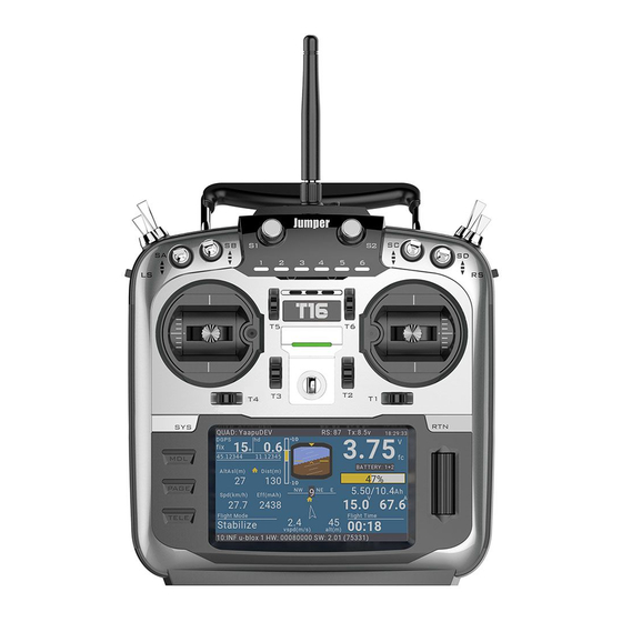
-
Contents
-
Table of Contents
-
Bookmarks
Quick Links
16-Channel Digital Proportional R/C System
使用说明书
ATTENTION
● Please read this manual carefully before use.
● Please keep this manual in a safe place after reading.
Digital Proportional R/C System
Related Manuals for Jumper T16
Summary of Contents for Jumper T16
-
Page 1
16-Channel Digital Proportional R/C System 使用说明书 ATTENTION ● Please read this manual carefully before use. ● Please keep this manual in a safe place after reading. Digital Proportional R/C System… -
Page 2
The information contained in this manual is subject to change without notice. This T16 transmitter is suitable for all types of models of fixed wings, gliders, helicopters and multi-rotors. The model type can be selected according to the body used, and various mixing functions can be used. -
Page 3
Components… -
Page 4: Table Of Contents
Table of Contents 1. Overview……………………..3 1.1. Disclaimer ……………………3 1.2. Legal status and copyright ………………3 2. installation……………………..4 2.1. ready …………………….. 5 2.2. Backup remote firmware ……………….. 7 2.3. Backup models and settings ………………8 2.4. Upgrade remote firmware using Companion software ……….10 2.5.
-
Page 5: Overview
1. Overview JumperTX is a firmware that runs on the T16. Its main purpose is to support the receiver of more protocols, thus developing all the potential of the remote control. The core of the JumperTX firmware is based on the modified Er9x firmware system of the Turnigy/Flysky9xTM remote.
-
Page 6: Installation
Select the Write Firmware option after booting and select the appropriate firmware upgrade. In BOOTLOADER mode, you can also use USB to connect to a computer. You can use your computer to access the T16 disk data. After plugging in the USB, the display is as follows.
-
Page 7: Ready
If you are upgrading an older version of JumperTX firmware, it is highly recommended that you back up your remote’s configuration file to make sure you don’t lose any model or remote- control configuration. Windows driver installation. The T16 uses the STM32 Bootloader driver. Can be downloaded here: Https://zadig.akeo.ie/…
-
Page 8
Turn off the T16 and connect to the computer using the USB cable. Open the downloaded Zadig software (some systems need to run in administrator mode, you can use right click and select to run as administrator) Click Options and select List All Devices. (as shown below) Click on the drop-down list to select STM32 BOOTLOADER (as shown below) Click Install Driver. -
Page 9: Backup Remote Firmware
Open the Companion software and set the remote control model to T16 in the setup menu. Turn off the remote control or enter BOOTLOADER mode, connect the computer with a USB cable.
-
Page 10: Backup Models And Settings
After the backup is complete, you can see the backup file under the path you just selected. 2.3. Backup models and settings Open the Companion software and set the remote-control model to T16 in the setup menu. Put the remote control into BOOTLOADER mode and connect the computer with a USB cable.
-
Page 11
Click on the file and select Save As (as shown below) In the pop-up dialog box, you can choose where to save the backup file and the file name you want to save. Click Save to start the backup (as shown below) -
Page 12: Upgrade Remote Firmware Using Companion Software
Note: Before disconnecting the USB connection, remember to eject the device and then disconnect it to prevent damage to the contents of the SD card file. 2.4. Upgrade remote firmware using Companion software Too be added, not currently supported 2.5. Companion Software Introduction Too be added, not currently supported 2.6.
-
Page 13
Switch Warning: This is a warning that the remote-control switch is not in the default position. (The default setting is that all switches default backwards to the end) Out of control protection is not set Warning: This is a warning that the remote control’s runaway protection is not set. -
Page 14
Alarm Off Warning: A similar warning will appear if the sound mode of the Remote Control Settings page is set to Mute. SD card warning: This warning will appear if the version of the SD card file used does not match the firmware version. (Update the firmware and also need to update the SD card content) -
Page 15: Main Interface
2.7. Main interface The default boot screen is as follows; the user can add the content to be displayed to customize the main interface. Top menu bar: The default top menu bar displays speaker volume, remote battery level, receiver signal strength (RSSI), and time and date. Users can also add other display information.
-
Page 16
Model Select: The Model Selection menu is used to create new, select to switch, delete and copy models. Monitors: Used to display the monitoring interface of channel output, mixed output and logic switch. You can use the page up button (PAGE) to switch other interfaces. The logic switch page can display the status of 64 logic switches. -
Page 17
Reset…: Used to call up various reset options. Reset flight: reset all timers and digital values (if there is an alarm when booting, it will reappear) Reset timer1, 2, 3: Reset a single timer. Reset telemetry: Reset the number of values. -
Page 18
Statistics: Show some statistics. This page displays flight statistics and throttle usage charts. Session: Current session time. Battery: Time since the last charge. Throttle, Throttle%: Throttle statistics, Throttle% set the time to run according to the throttle setting. The graph shows the value of the throttle channel as a function of time. Timers1, 2, 3: Timer statistics. -
Page 19
This page shows the raw data readings from the radio analog input device, with raw data on the left and -100 to 100 values on the right side of the analog input. The TELE key function is used to set user interface options, including top bar settings and main view screen layouts, which are very flexible due to the use of widgets. -
Page 20
Layout: There are 2 medium-sized widget areas on the left side of the default layout and 1 large area on the right side. The active layout is highlighted in white. There are 5 options, from 1 large area to 8 small areas. Press the ENT key to enter the edit mode (the icon changes from the currently selected white to red), then use the scroll wheel to select the layout option (or use the [TELE] and [SYS] buttons) to confirm the selection by pressing the ENT key. -
Page 21
to the widget settings page with the cursor on the first item in the selected category. Then you can scroll up/down from there and press ENT to select the source. Min, Max: The range allowed to be set. Color: Allows custom colors. Timer: Displays the timer value. -
Page 22
Press the PAGE key to enter the User Interface settings page. Theme: theme selection. Background color: Sets the RGB value of the background color. The default is R:248, G:252, B:248. Main color: Sets the RGB value of the foreground color. The default is R:224, G:32,:B:24. Top Bar: There are 4 small areas that can be used to add widgets to the Top Bar. -
Page 23: System Settings
Press the ENT key to enter the setting and use the scroll wheel to select the part to be set. 2.8. System settings The System Setup menu is used to configure the remote hardware section and set global features for all models. RADIO SETUP: The remote control settings page is used to configure settings common to all models.
-
Page 24
NoKey: Beep, no sound when the button is pressed. Alarm: A beep will only sound when an alarm occurs, such as a battery voltage alarm. Quiet: Silent mode, no alarm sound will be emitted (set this mode, there will be an alarm off warning every time you turn it on) Volume: Master volume. -
Page 25
Inactivity: No action alarm for a long time. When set to 0, the alarm is turned off. Sound off: Check to turn off the sound. Check RSSI on Shutdown: Check to enable this alarm, which will be triggered if the remote is turned off without the aircraft being powered off. -
Page 26: Sd Card
Units: The number of values will be displayed in metric or imperial depending on this setting (Metric Metric, Imperial Inch) FAI Mode: Disables all digital display except RSSI and RxBt to comply with the game regulations (requires Companion software check function). Play delay: This delay is the delay that does not report the midpoint of the switch when the midpoint of the 3-segment switch is reached.
-
Page 27: Global Function
SxR: Frsky SxR series receiver setup script. THEMES: Remote control interface theme folder. WIDGETS: Some gadget scripts. 3.0. Global Functions The global functions GF1 to GF64 allow you to define standardized functions available for all modes, such as specific switches, potentiometers, sliders or settings, which avoids having to set the same function on each model, model-specific functions in «model settings (MODEL SETUP) ) in the «SPECIAL FUNCTIONS»…
-
Page 28
Use the scroll wheel to select up and down, then press the ENT key to confirm, then select the source to be set and press the ENT key to confirm (the front with the «!» symbol is reversed, such as SA and !SA, where !SA is the reverse SA) Next select the function in the list of available functions (some features have a second parameter setting available) !1X: Play this function once (do not play when booting) -
Page 29: Trainer Mode
Trainer 3.1. This page is used to configure the master remote control settings for the coach mode, which are activated by setting the Trainer Mode to Master in the MODEL SETUP page. The mode can be set for 4 basic channels. OFF: Channels that do not use the coach mode.
-
Page 30
Set an enable switch, such as SA on the graph (the arrow represents the enabled switch position) Select Trainer and set the parameter to «—«. Finally check to enable this feature. Add the following settings to the slave. In the Model Setup page, set the Trainer Mode to Slave / Jack. Turn off the internal and external tuner modules. -
Page 31: Hardware
Then the slave will center the joystick, select Cal and press the ENT key to calibrate the input. After calibration, the 4 values should be close to 0.0. 3.2. Hardware This page lists the hardware physical input device types. A short three-character name can be given for identification on the setup page.
-
Page 32: Version Information
Sticks: 4 basic channel control joysticks. Pots: S1, 6P, S2, they can be configured to: None Multipos Switch Pot with detent Max Bauds: The maximum baud rate of the external module can be switched between 115200 and 400000. Bluetooth: Can be set to Bluetooth Telemetry or Bluetooth Trainer mode, the default is off.
-
Page 33
Boot the main interface Long press the ENT key to select the Model Select menu, then press the ENT key (as shown below) Long press the ENT key to open the new model and other management menus (as shown below) -
Page 34
Select Rename category and press ENT to modify the category name (as shown below) To edit the category name, use the scroll wheel to select alphanumeric characters and characters, press the ENT key to select, while the cursor is selected to move to the next letter, long press the ENT key to switch between upper and lower case, short press the SYS button to move the cursor to the left, short press TELE Move the cursor to the right and press RTN to exit the edit mode. -
Page 35: Model Setting
Use the scroll wheel to select the model you want to use, long press the ENT key to select Select model to switch the model. 3.5. Model Setup The model settings cover all the initial settings required. The Model Setup Model Setup page contains the following features: 1.
-
Page 36
9. Enable throttle adjustment for idle only. 10. Set up pre-flight inspection. 11. Set the display checklist. 12. Enable the center beep on the selected control. 13. Set up the internal RF module. 14. Set up the external RF module. 15. -
Page 37
Timers: There are 3 timers that can be set to count up or down. If set to 00:00:00, they will start from 0, otherwise they will count down. Source: Set how to trigger the timer. When set to ON, it will always count. When set to THs, the throttle will start timing. -
Page 38
Throttle Reverse: Check to reverse the throttle. Throttle Source: Defines the joystick that triggers the THx option, typically set to throttle. Throttle Trim Idle Only: IC engine mode. Preflight Checks: A set of security features that take effect when the remote is powered on or when the model is loaded from the model list. -
Page 39
D16: For the current 16ch bidirectional full duplex transmission, also known as X mode. For X series receivers. D8: Applies to the older 8ch bidirectional mode. LR12: Applicable to the current 12ch one-way long distance. Channel Range: Set the channel range. (D16 mode sends data every 9ms, 8 channels at a time, 16 channels need to send once every 18ms, so removing unnecessary channels can reduce the delay) Receiver No.: Only for the D16/LR12 protocol. -
Page 40
Failsafe Mode: Out of control protection settings. (D16/LR12 protocol only) Hold: Holds the last output value. (For example, 50% throttle is out of control, the receiving opportunity keeps 50% throttle until the signal is restored) Custom: Customize the runaway protection receiver output value. Select Set to enter the runaway protection custom settings page, and you can set the runaway protection value separately for each channel. -
Page 41
Note: You must carefully test the selected runaway protection settings for proper operation before taking off. Antenna selection: Allows selection of two internal antennas or an external antenna and reminds you to ensure that an external external antenna is connected when this option is selected. -
Page 42: Helicopter Setup
Bind on powerup: The remote control is switched on when the power is turned on, and some protocols are optional. Low power mode: Some protocol optional features. R9M: Frsky 900MHZ tuner module. RF Power: Set the R9M module transmit power. SBUS: Turn on the external tuner SBUS output.
-
Page 43: Flight Modes
The output of the CCPM mixer is CYC1, CYC2 and CYC3, and the servo channel needs to be assigned on the MIXER page. Swash Type: Swashplate type selection (90, 120.120X, 140). 120X means that cyc1 is rotated by 90 degrees. Swash Ring: The value is 0-100.
-
Page 44
There are 8 flight modes plus the default FM0 available. The first switch of FM1-8 is valid. When no switch is turned on, the default FM0 is valid. This explains why FM0 has no switches. Name: Each flight mode can have a 10-character name. Switch: Each flight mode has an optional activation switch (physical or logical) Trim selection array: Fine-tuning arrays have the following features. -
Page 45: Input
Inputs->Mixer->Outputs: This is the top 3 pages of the remote control. Because JumperTX is very flexible and powerful, there is no standard mixing settings, and there are many ways to set the same effect. For this reason, the best practice is to describe the actual operation directly, so that you can develop a logic and a consistent way to write all the models.
-
Page 46
It is highly recommended to always create a last line that is not restricted by the switch or flight mode. This is to ensure that even if an invalid logic or switch failure invalidates other lines, at least the line will still be active, thus avoiding this. -
Page 47
Input name: Use the scroll wheel to select letters or numbers, long press the ENT key to switch between upper and lower case, short press the ENT key to switch to the next character. Line name: Because there can be multiple lines of configuration input, naming each line provides a label indicating the purpose of the line to avoid confusion. -
Page 48
(SrcValue x weight)+Offset =Result (100 x -50/100)+50=0 (0 x -50/100)+50=50 (-100 x -50/100)+50=100 Curve: Diff: The differential (usually down the aileron stroke) is used to reduce unfavorable yaw and improve cornering/maneuvering characteristics. (Default = 0, range -100 to +100). Although available here, it is best to set it on the mixing page. -
Page 49: Mixer
Switch: The switch position (physical or logical) can enable/disable this input line. The Side: Side parameter limits the effect of the line to only one side of the source: — (enabled within the full source range) x>0 (enabled only when source > 0) x<0 (enabled only when source >…
-
Page 50
Note that each row that is currently active and contributes to the channel output will display its source in bold. This is useful for debugging when many lines are set on the channel and the switch function is checked. Use the scroll wheel to select the mix list, press and hold the ENT key to enter the edit submenu. -
Page 51
Mix name: Use the scroll wheel to select letters and numbers, long press the ENT key to switch between upper and lower case. Short press the ENT key to set the next character. Source: Long press the ENT key to open the submenu for selecting the input source by category. -
Page 52
Curve: Diff: The differential (usually lower than the aileron stroke) is used to reduce unfavorable yaw and improve steering/maneuvering characteristics. (Default = 0, range — 100 to +100) Although Diff can also be used in input, it is usually used in mixing. Expo: The default curve is Expo, which by default is 0, which means that the response is linear (ie no curve) positive values make the response weaker around 0, while negative values make the response sharper. -
Page 53: Outputs
Multpx: The Multpx setting defines how the current mixline interacts with other mixlines on the same channel. Add: Add to output. Multiply: Multiplies the results. Replace: Replace. The combination of these operations allows for the creation of complex mathematical operations and is often considered one of the biggest benefits of using JumperTX.
-
Page 54: Curves
Min and Max limits: These are «hard» limits, ie. They will never be covered. Note that they are used as gain or “end point” settings, which can be extended to +/- 150% by checking the “Extended limits” option on the “Model Setup” page. For multi-rotor and helicopter flight controllers, the minimum and maximum limits must usually be adjusted to match your remote control travel to the expected flight controller travel.
-
Page 55
The curve can be between 2 and 17 points and can have a fixed or user definable x coordinate. The X value represents the input and the Y value represents the output. Name: For convenience, you can name the curve. Type: Standard: Only Y points can be edited, ranging from -100 to 100. -
Page 56: Global Variables
Press and hold the ENT key on the coordinate point to enter the submenu: Preset: Allows selection of standard preset linear curves with slopes of -45, -33, -22, -11, 0, 11, 22, 33, 45. These can also be used as a starting point for more complex curves. Mirror: The curve will be mirrored vertically.
-
Page 57
Name: Set the name. Unit: For reference only, switch between normal and %. Precision: When switching to «0.0», the Gvar value is divided by 10 for the logic switch. This is necessary because, for example, Thr: -100 to 100 and GVars: -1024 to 1024. -
Page 58: Logical Switches
4.3. Logical Switches The logic switch is a user-programmed virtual switch. They are not physical switches that flip from one location to another, but they can be used as program triggers just like any physical switch. By evaluating the input conditions for the programming of the logic switches, they are turned on and off (logically they become true or false).
-
Page 59
a<x: If the value of the selected source «a» (V1) is less than «x» (V2), the condition is True, which is the programmed value. |a|>x: If the absolute value of the selected source «a» (V1) is greater than «x» (V2), the programmed value, the condition is True. -
Page 60: Special Functions
|d|>x: If the absolute value of «| d |» is changed, the condition is True in the selected source (V1), greater than «x» (V2), a programmed value. (Absolutely means to ignore whether a is positive or negative.) Timer: The logic switch is turned on and off continuously. It turns on time (V1) and turns off time (V2).
-
Page 61
Reset the telemetry value. Adjust global variables — Allows neat features, such as optimizing settings in flight. Adjust the volume. Play sounds, tracks, background music and/or vibration (tactile) feedback. Run the Lua script. Adjust the screen backlight. Save the screenshot to the SD card. Control data logging. -
Page 62
Then you can scroll up/down from there and press ENT to select the source. Function: The following functions are triggered by the switch selected above. Override: Forces the selected channel output (CH1 to CH32) to be a specific value between -100 and +100. This check box enables or disables this line. Caution: This function does not consider the minimum/maximum value and direction specified in the output menu, so the servo may be overdriven. -
Page 63
Checkbox: Enable/disable this line. Set: Time1, 2, 3: This function will preset the selected timer (00:00:00). Check the box to enable or disable this line. Adjust: Allows adjustment of global variables (GV1 to GV9). There are four options for «—«: Value (between -500 and +500) Source (normal control range) GVAR, another global variable… -
Page 64
Pressing the ENT key while the mixing source is active will display the submenu of the source by category. Scroll up/down to the desired category and press the ENT key. It takes you back to the parameter being edited on the first item in the selected category. Then you can scroll up/down from there and press ENT to select the source. -
Page 65: Custom Scripts
Select «—» and press and hold the ENT key to pop up the menu showing the source by category. Scroll up/down to the desired category and press ENT, which takes you back to the special features page with the cursor on the first item in the selected category. Then you can scroll up/down from there and press ENT to select the source.
-
Page 66
Various applications for web applications and image processing, in this case for implementing custom functions in the radio. There are three basic types: One-time: The script only runs once and then terminates. For example, the receiver and flight controller setup scripts, as well as the new Create Model Wizard. They are executed from the /SCRIPTS/folder on the SD card. -
Page 67: Telemetry
You can select a script in the first line and optionally define a custom name to know what to use in the second line. The screen also displays the inputs and outputs used by the script. Basic layout of Lua scripts The user-written lua script is basically a subroutine called by the main loop of the remote control code.
-
Page 68
sensor type: RSSI Receiver Signal Strength Indicator (RSSI): The value transmitted by the receiver in the model to the remote control, indicating the strength of the received signal. Warnings can be set to warn below the minimum value, indicating that you are out of range. Factors affecting signal quality include external interference, excessive distance, poor orientation, or antenna damage. -
Page 69
All found sensors are automatically displayed during the discovery process. If no S.port sensor is plugged into the receiver, only the sensor that comes with the receiver can be found and set. Add a new sensor: Allows you to manually add new sensors. Short press the ENT key to call up the Add New Sensor menu. -
Page 70
If Ratio is «-«, the telemetry value is calculated as follows: (sensing value divided by 10) (received value/10) + Offset=displayed value Or, if Ratio is not «-«, the telemetry value is calculated as follows: [(received value / 255) * Ratio] + Offset = displayed value The ratio allows the received sensor values to be corrected or converted, for example between km / h or between sections. -
Page 71
The Lipo voltage sensor FLVSS adds the following parameters to the list: Cels: Total battery voltage. In order to get a single battery voltage, a new calculation sensor needs to be defined. Name: Cmin or Cmax. Type: Calculated Formula:Cell Cell sensor: Select from active Lipo voltage sensors, for example, Cels. Cell Index: lowest, 1, 2, 3, 4, 5, 6, highest. -
Page 72
Sensor: Curr Unit: mAh Persistent: When selected, this value will remain during power down and resume during power up. Logs: If checked, will be logged to the SD card. Please note that the record must still be started by the Special Function. Variometer settings: The vario sensor adds the Vspd and Alt parameters to the sensor list. -
Page 73: Delta Wing
4.7. Simple delta wing setup example 1. First set the channel order (shown as AETR): 2. Create a blank new model:…
-
Page 74
Select New Model and press the RTN button to exit the wizard in the New Model Wizard interface that pops up. 3. Model settings: The Model Settings section contains all the initial settings required for input, mixing, output, and more. Model name: Enter your model name. -
Page 75
4. Determine the required servo/channel: With 32 output channels available, you can assign channels completely freely. Normally, the channel with the lowest number will be assigned to the servo because the channel number maps directly to the channel in the receiver. CH1: Lifting left. -
Page 76
Move the cursor to Ail, long press ENT to enter the edit pop-up window, then select the Edit option and press ENT. We use the 15% Expo curve to moderate the response around the neutral point (this can be adjusted to your liking). You can insert a new input line by moving the cursor to the input to which you want to add a line, then long press the ENT key to bring up the edit menu. -
Page 77
Only one input line is active at a time. If the switch SA fails, the last line will become True, which may not be the case if the Aile Hi and Elev Hi switch positions are set to SA↓. 7. Determine the interaction between the input and the channel: For example, CH1 moves up and down. -
Page 78
9. Configure the output: The next step is to adapt the pure logic output of the mixing phase to the mechanical properties of the model. Here you can configure the minimum and maximum stroke outputs, channel inversion, and adjust the servo center point using PPM center adjustment, or add offset using subtrim. Introduction to global variables: We can also use global variables to set the value of delta wing mixing. -
Page 80
Add a voice prompt: You can set the prompt voice for the switch to play when the switch is in the set position. Global features: Global features can be used to set standardized features that can be used by all models. The following example will define a global function, using the left slider LS as the volume control, which eliminates the need to enter the «Radio Setup»… -
Page 81
The ESC expects a complete control signal range of -100 to +100, so the Weight and Offset of the Thr input can be left at the default value. Press RTN to return (input) the Inputs page 2. Configure the Mixing (MIXER) page:… -
Page 82
Go to the Mixer page, scroll down to CH3 and press ENT to assign Thr to CH3. The Mixer page should be displayed as shown below. 3. Configure the Outputs page: Unable to provide accurate settings because the settings depend on the actual characteristics of your model… -
Page 83
4. Set the throttle lock function: The throttle lock function can be set to a switch to cut off the throttle passage to prevent misoperation. A logical unlock switch can be set to unlock when the unlock condition is met. -
Page 84
If the throttle stick is very close to -100 and the switch SD is in the «up position», then L01 becomes true, and if the lift stick is very close to -100 and the logic switch L01 is true, then L02 becomes true. If L02 remains true for at least 2 seconds, L03 is locked ON, and L03 is reset when the SD switch is dialed up.
6 Floor, Buliding 2, ZhiGu Tech Park, 2259#LongCheng RD,ZhongLou District, ChangZhou, China
+86-0519-69815295
Mon – Fri 8:30 – 18:00
Email :support@jumper-rc.com
Copyright © 2020 Jumper. All Right Reserved.
- Home
- Contact
- Support
- About Us
About the latest offers and deals Subscribe today!
YouTube

Digital Proportional R/C System
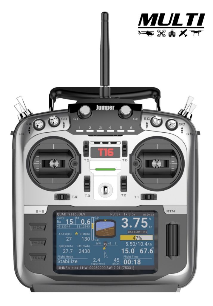
Resources
ATTENTION
- Please read this manual carefully before use.
- Please keep this manual in a safe place after reading
Introduction
Thank
you for purchasing the Jumper® JumperTX-2.4GHz System T16 Remote Control. The
system is versatile and can be used by beginners and professionals. Please read
this instruction manual carefully before use to ensure correct and safe use.
Due to version upgrades, there have been changes. The information contained in this
manual is subject to change without notice.
This
T16 transmitter is suitable for all types of models of fixed wings, gliders,
helicopters and multi-rotors. The model type can be selected according to the
body used, and various mixing functions can be used.
Relevant
precautions for use, export, etc.:
- This product can be used in unmanned aerial vehicles. It does not apply to any application other than unmanned aerial vehicle control.
- Precautions when exporting
- This product is subject to regulations in the country of manufacture. Users or companies importing. This product must ensure the product meets regulatory requirements in their country.
- This product may have restrictions on applications and use specific to y our region. Please ensure you comply with local regulations when operating.
- This product is intended only for use with RC Models.
Flight Safety:
We recommend that you fly to dedicated model airspace, paying special attention to the rules of the arena, as well as the location, wind direction and any obstacles on the field. Be very careful in areas flying around wires, high-rise buildings or communication facilities, as nearby may there is radio interference.
The contents of this manual are subject to change without notice. If there are any errors or omissions in this manual, please contact us, we will correct them as soon as possible, and indicate your corrections.
Components

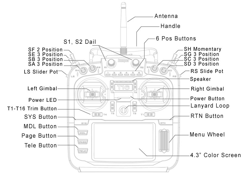
Table of Contents
1. Overview.
1.1. Disclaimer
1.2. Legal status and copyright
2. installation.
2.1. ready.
2.2. Backup remote firmware
2.3. Backup models and settings
2.4. Upgrade remote firmware using the Companion software
2.5. Companion Software Introduction
2.6. First boot
2.7. Main interface
2.8. System settings
2.9. SD Card
3.0. Global function
3.1. Trainer Mode.
3.2. Hardware
3.3. Version Information
3.4. Model selection
3.5. Model setting
3.6. Helicopter setup
3.7. Flight Modes
3.8. Input
3.9. Mixer
4.0. Outputs
4.1. Curves
4.2. Global Variables
4.3. Logical Switches
4.4. Special Functions
4.5 Custom Scripts
4.6 Telemetry
4.7 Simple Delta Wing
11.1. Trainer Mode settings
11.1.1. Master mode
11.1.2. Slave mode
11.2. Set FPV or other external input
11.3. Use fine-tuning as a virtual switch
11.4. Swashplate mixing
11.5. Modify sound
12. Emulator
1. Jumper T16 Overview
JumperTX
is a firmware that runs on the T16. Its main purpose is to support the receiver
of more protocols, thus developing all the potential of the remote control. The
core of the JumperTX firmware is based on the modified Er9x firmware system of
the Turnigy/Flysky9xTM remote.
JumperTX
also has USB file management, making it easier to manage the remote via PC
software.
The
display of the main interface of JumperTX can be modified according to your
needs. You can display any input, switch, channel data and timer at random on
the main interface, and you can set each model separately.
JumperTX can connect to the flight simulator via a DSC line (PPM) or USB cable (USB HID).
JumperTX
also supports coaching and FPV settings.
JumperTX has been internationalized and has been translated into English (EN), Czech (CZ), Finnish (FI), Dutch (NL), Spanish (ES), French (FR), German (DE), Polish (PL) ), Italian (IT), Portugal (PT), Sweden (SE).
1.1 Disclaimer
JumperTX is an experimental firmware. No warranty or implied warranty is given as to the quality and reliability of this firmware. The RC model can cause serious injury or even death if not handled properly. If you decide to use JumperTX firmware, you will be solely responsible for your model. Any injury or damage caused by the use of JumperTX firmware,
The author of JumperTX is not responsible for
it. Please use it with caution.
1.2. Legal status and copyright
This project is free software: you may redistribute and/or modify it in compliance with the GNU General Public License, the V3 version of the agreement, or (optionally) the updated version of the agreement issued by the Free Software Foundation. You should receive a copy of the GNU General Public License Agreement for the JumperTX project. If not, see www.gnu.org/licenses.
The JumperTX firmware has been released and is expected to benefit the public, but it does not have any warranty; it does not even include an implied commercial license or applicability for a particular purpose. For more details, see the GNU General Public License.
JumperTX source files, etc. can be found at https://github.com/jumperXYZ.
2. Installation
Users can choose between two methods to install the JumperTX firmware.
1. Use the JumperTX firmware upgrade tool (Companion)
2. Upgrade the remote controller firmware using the SD card.
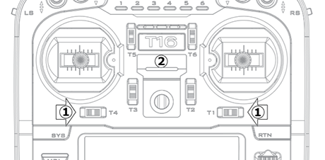
If you don’t have a WindowsTM operating system, choose the second method, “Upgrade Remote Controller Firmware with SD Card.” This is a BOOTLOADER application designed by the JumperTX developer team. It is efficient and simple. The upgrade requires two steps. First, you need to copy the downloaded firmware to the FIRMWARE directory of the SD card, then pinch the horizontal fine-tuning button and turn it on again (as shown below).
Select the Write Firmware option after booting and select the appropriate firmware upgrade.

In BOOTLOADER mode, you can also use USB
to connect to a computer. You can use your computer to access the T16 disk
data. After plugging in the USB, the display is as follows.

The preparation section describes what you need to do before you start installing the firmware. Then, depending on the tool you are using, the installation steps will overwrite the original program. These steps apply to version upgrades or installations of different versions and developer versions.
2.1. Ready
First, make sure your remote is fully charged
before you start installing firmware. in
Download T16 firmware (JumperTX 2.2.3 English) at https://www.jumper.xyz/downloads, where English is the menu language for the remote control. 2.2.3 refers to the version number of the JumperTX firmware. Note: Do not use the DfuSe tool downloaded from STMicroelectronics!
You can download the firmware upgrade tool
here:
Https://www.jumper.xyz/downloads
If you are using WindowsTM, you will need to
install the appropriate USB driver. See the Windows Driver Installation
section.
Unzip and install the downloaded tool.
If you are upgrading an older version of
JumperTX firmware, it is highly recommended that you back up your remote’s
configuration file to make sure you don’t lose any model or remote-control
configuration.
Windows driver installation.
The T16 uses the STM32 Bootloader driver. Can be downloaded here:
https://zadig.akeo.ie/

Turn off the T16 and connect to the computer using the USB cable. Open the downloaded Zadig software (some systems need to run in administrator mode, you can use right-click and select to run as administrator). Click Options and select List All Devices (as shown below)

Click on the drop-down list to select STM32 BOOTLOADER (as shown below)

Click Install Driver (If you have previously installed the STM32 driver, this button will display Reinstall Driver, as shown below)

After the installation is complete, the
following devices in the Computer Device Manager indicate that the installation
is complete.

2.2. Backup remote firmware
Before upgrading the remote
control firmware, it is recommended to back up the firmware and model
configuration file of the current remote control to prevent loss.
Open the Companion software
and set the remote control model to T16 in the setup menu.
Turn off the remote control
or enter BOOTLOADER mode, connect the computer with a USB cable.
Click the read/write menu and select to read the firmware from the remote control (as shown below)

In the pop-up dialog box, you can choose where to save the backup firmware and the file name you want to save.

Click Save to start backing up the firmware.

After the backup is complete, you can see the backup file under the path you just selected.
2.3. Backup models and settings
Open the
Companion software and set the remote-control model to T16 in the setup menu.
Put the remote
control into BOOTLOADER mode and connect the computer with a USB cable.
Click the
read/write menu and select to read the model and configuration from the remote
control (as shown below)

Click on the file and select Save As (as shown below)

In the pop-up dialog box, you can choose where to save the backup file and the file name you want to save. Click Save to start the backup (as shown below)

Note: Before disconnecting the USB connection, remember to eject the device and then disconnect it to prevent damage to the contents of the SD card file.
2.4. Upgrade remote firmware using the Companion software
To be added, not currently supported
2.5. Companion Software Introduction
To be added, not currently supported
2.6. First boot
Press and hold the power button to turn on the machine. Before entering the main interface, the system will check the position of the throttle stick and switch and other starting conditions. If the starting condition is not met, there will be a corresponding error prompt, which requires user operation to clear or press any key to jump. Over.
Throttle warning: This is a warning that the throttle is not at the lowest position when starting. You can put the throttle stick to the lowest position or press any key to skip, or you can close it in the Throttle state option in the MODEL SETUP. Throttle alarm.

Switch Warning: This is a warning that the remote-control switch is not in the default position. (The default setting is that all switches default back to the end)

Out of control protection is not set Warning: This is a warning that the remote control’s runaway protection is not set.

Alarm Off Warning: A similar warning will appear if the sound mode of the Remote Control Settings page is set to Mute.

SD card warning: This warning will appear if the version of the SD card file used does not match the firmware version. (Update the firmware and also need to update the SD card content)

2.7. Main interface
The default boot screen is as follows; the user can add the content to be displayed to customize the main interface.

Top menu bar: The default top menu bar displays speaker volume, remote battery level, receiver signal strength (RSSI), and time and date. Users can also add other display information.
Model menu bar: The model menu bar on the right shows the model name and model image currently in use. Model submenu: Press and hold the ENT key to enter the model submenu.

Model Select: The Model Selection menu is used to create new, select to switch, delete and copy models.
Monitors: Used to display the monitoring interface of channel output, mixed output and logic switch.

You can use the page up button (PAGE) to switch other interfaces.
The logic switch page can display the status of 64 logic switches. The default is that the active state is gray and black is active.
Reset…: Used to call up various reset options.

Reset flight: reset all timers and digital values (if there is an alarm when booting, it will reappear)
Reset timer1, 2, 3: Reset a single timer.
Reset telemetry: Reset the number of values.
Statistics: Show some statistics.

This page displays flight statistics and throttle usage charts.
Session: Current session time.
Battery: Time since the last charge.
Throttle, Throttle%: Throttle statistics, Throttle% set the time to run according to the throttle setting. The graph shows the value of the throttle channel as a function of time.
Timers1, 2, 3: Timer statistics.
Press and hold the ENT key to reset this page and press the PAGE key to turn the page.

This page shows system debugging information, primarily for developers and debugging Lua scripts.

This page shows the raw data readings
from the radio analog input device, with raw data on the left and -100 to 100
values on the right side of the analog input.
The TELE key function is used to set user interface options, including top bar settings and main view screen layouts, which are very flexible due to the use of widgets.
User Interface: User interface options allow the selection of themes as well as custom foreground and background colors. This page also applies to the top bar settings. The top bar is displayed at the top of the main view, and the right side includes status indicators for sound, battery and RSSI levels, as well as time and date.
Main view: Up to 5 main views can be defined to display various widgets that can display images, radio information, and all telemetry. Five different layout options can be selected between full screen or up to 8 widget areas.
Main view settings: Press and hold the TELE button to enter the telemetry and user interface settings page.

Layout: There are 2 medium-sized widget areas on the left side of the default layout and 1 large area on the right side. The active layout is highlighted in white. There are 5 options, from 1 large area to 8 small areas. Press the ENT key to enter the edit mode (the icon changes from the currently selected white to red), then use the scroll wheel to select the layout option (or use the [TELE] and [SYS] buttons) to confirm the selection by pressing the ENT key. Press the RTN button to exit the edit mode.
Setup widgets: Once you have selected the main view layout, you can set up the small window next. Scroll down to “Setup widgets” and press ENT to enter edit mode.

Use the scroll wheel to select the area and press the ENT key. A list of available widgets will pop up and a scroll arrow will appear on the right. Scroll through the options until you find the part you want, then press the ENT key to enter edit mode.
Standard widget:
Outputs: Displays multiple channel outputs.
First
channel: Select the first channel number to display.
Fill
Background? If selected, the background fill color will be used.
BG
Color: Sets the RGB value of the background color.
Value: Displays the value of the source.
Source:
Select the source to display.
Color:
Sets the RGB value of the text.
Shadow:
Add a shadow to the text.
ModelBmp: Displays the model image set in the
Model Setup page.
Text: Displays the specified text in the
widget.
Text:
The text to display.
Color:
Sets the RGB value of the text.
Size: Determine the size of the text, from Standard, Tiny, Small, Mid to Double.
Shadow:
Add a shadow to the text.
Gauge:
The bar shows the selected source.
Source:
Press and hold the ENT key to enter the submenu for selecting the input source
by category. Scroll up/down to the desired category and press ENT, it will return
to the widget settings page with the cursor on the first item in the selected
category. Then you can scroll up/down from there and press ENT to select the
source.
Min,
Max: The range allowed to be set.
Color:
Allows custom colors.
Timer:
Displays the timer value.
Timer1/2/3.
BattCheck:
Displays battery parameters.
Sensor:
Select the battery sensor.
Color:
Sets the RGB value of the text.
Shadow:
Add a shadow to the text.
Counter:
Display a counter.
Option
1: Select Enable Source.
Option
2: Select the XXXX source.
Option
3: Select the RGB value of the text.
Shadow:
Add a shadow to the text.
Edit
widget:
Once
the widget is created, it can be edited using the widget edit menu as follows:
Press the TELE button on the main interface and select Setup widgets to enter the settings interface. Select the widget you want to edit and press the ENT key. If the widget area is empty, the widget selection menu pops up. If the widget already exists, the widget edit menu pops up. Press and hold the ENT key to bring up the Edit submenu.

Add another main view: Up to 5 main views can be defined. Press PAGE to select Add.

按PAGE键进入User Interface设置页面。

Theme: theme
selection.
Background color: Sets the RGB value of the background color. The default is R:248, G:252, B:248.
Main color: Sets the RGB value of the foreground color. The default is R:224, G:32, B:24.
Top Bar: There are 4 small areas that can be used to add widgets to the Top Bar. Select Setup and press the ENT key to enter the settings.

Press the ENT
key to enter the setting and use the scroll wheel to select the part to be set.
2.8. RADIO SETUP
The System Setup menu is used to configure the remote hardware section and set global features for all models.

RADIO
SETUP: The remote control settings page is used to configure settings common to
all models. Press and hold the SYS button to enter.
Date/Time:
The date and time of the remote.
Battery
meter range: The battery voltage range. If the range is set incorrectly, it
will affect the display of the battery icon on the main interface.
Sound
Mode
All: A beep will sound and the button will
sound.
NoKey: Beep, no sound when
the button is pressed.
Alarm: A beep will only
sound when an alarm occurs, such as a battery voltage alarm.
Quiet: Silent mode, no alarm sound will be emitted (set this mode, there will be an alarm of warning every time you turn it on)
Volume: Master volume.
Beep volume: The amount of sound.
Beep length: The duration of the beep.
Beep pitch: beep sound tone, range 0-300Hz.
Wav volume: The volume of the Wav file.
Background Volume: The volume of the background
music.
Variometer
Volume:
Pitch at zero:
Pitch at max:
Repeat at zero:
Haptic: Vibration settings.
Mode: Similar to the alarm sound setting.
Length: Similar to the alarm sound setting.
Strength: Set the amplitude of the vibration.
Alarms
Battery low: Battery alarm
voltage.
Inactivity: No
action alarm for a long time. When set to 0, the alarm is turned off.
Sound off: Check to turn off the
sound.
Check RSSI on Shutdown: Check to
enable this alarm, which will be triggered if the remote is turned off without
the aircraft being powered off.
Backlight
Mode
ON: The backlight is always on.
Both: The backlight will illuminate when the
remote control is in operation.
Controls: The backlight will illuminate when
the remote control is in operation, but the button will not light.
Keys: The backlight will illuminate when any
key is pressed.
OFF: The backlight will not light when the
remote control is operating.
Duration: Backlight duration.
ON brightness: Controls the
brightness when the display is turned on.
OFF brightness: Controls the
brightness when the display is off.
Alarm: The backlight flashes when the
alarm is activated.
GPS
Time zone: Adjust the time according to
UTC, which can be set between -12 and +12.
Adjust RTC: If enabled, the remote time
will synchronize the GPS time on the model by postback.
Coordinate format: coordinate format
(DMS= Degrees, Minutes, Seconds=degrees, minutes, seconds)
Country code: If you live in the US, Europe or
Japan, you must select your country to ensure that the remote control meets the
requirements of your region.
Voice language: The language of the alarm
voice.
Units: The number of values will be displayed in metric or imperial depending on this setting (Metric Metric, Imperial Inch)
FAI Mode: Disables all-digital display except RSSI and RxBt to comply with the game regulations (requires Companion software check function).
Play delay: This
delay is the delay that does not report the midpoint of the switch when the
midpoint of the 3-segment switch is reached. The default value is 150ms.
USB Mode: You
can set the default mode for plugging in USB. There are Joystick and Mass
Storage options. If you set it to Ask, you will have a pop-up menu to select
the mode to use when you plug in the USB.
Default Channel
Order: Sets the order of 4 basic channels (the new model takes effect after the
setting is completed). The default is TAER (Spektrum/JR channel order), and
AETR is the channel order of Futaba/Hitec.
Mode: Set the
remote joystick mode (Mode 1 Japanese hand, Mode 2 American hand)
2.9. SD Card
This page has access to SD Card content.

CROSSFIRE:
LUA script for Black Sheep tuner.
FIRMWARE: Remote
controller firmware upgrade directory (downloaded remote controller firmware is
added to this folder to upgrade)
IMAGES:
Model image folder.
LOGS:
Log folder.
MODELS:
This folder contains model information.
RADIO:
SCRIPTS: Lua script folder.
SOUNDS:
Voice folder.
SxR:
Frsky SxR series receiver setup script.
THEMES: Remote control interfaces theme folder.
WIDGETS: Some gadget scripts.
3.0. Global Functions
The global functions GF1 to GF64
allow you to define standardized functions available for all modes, such as
specific switches, potentiometers, sliders or settings, which avoids having to
set the same function on each model, model-specific functions in “model
settings (MODEL SETUP) ) in the “SPECIAL FUNCTIONS” page of the
section.

The following figure shows
the system volume display using the right slider (RS).

Source: The source determines the content of the special function enabled (short press the ENT key and then long-press the selection source)

Use the scroll wheel to select up and down, then press the ENT
key to confirm, then select the source to be set and press the ENT key to
confirm (the front with the “!” symbol is reversed, such as SA and
!SA, where !SA is the reverse SA)
Next, select the function in the list of available functions (some features have a second parameter setting available)
!1X: Play this function once (do not play when booting)
1X: Play this function once
1s-60s: Set the interval to repeat this function.
If a checkbox is displayed at the end, you can simply disable the feature by unchecking the box.
Press and hold the ENT key on the global function you have defined, you can display an edit menu to copy, insert, and clear the function.

3.1. Trainer
This page is used to configure the master remote control settings for the coach mode, which are activated by setting the Trainer Mode to Master in the MODEL SETUP page.

The mode can be set for 4 basic channels.
OFF: Channels that do not use the coach-mode.
+=: Select the add mode, the coach and
the student can operate the channel.
:=: Set the mode to Replace so the student has full control. This is the normal user mode.
Usually
set to 100%, can be used to scale the input of the slave, the latter CH is the
channel map.
These
settings are the global settings available for each model. For each model that
wants to use the coaching function, you must specify a switch in the Special
Functions page.
In the Model Setup page, set the Trainer
Mode to Master / Jack.
In the “Special Functions”
page, add a special function as shown below.

Set an enable switch, such as SA on the graph
(the arrow represents the enabled switch position)
Select
Trainer and set the parameter to “—“.
Finally, check to enable this feature.
Add
the following settings to the slave.
In
the Model Setup page, set the Trainer Mode to Slave / Jack.
Turn
off the internal and external tuner modules.
Before using the coaching function, it is recommended to test whether the coaching function is available on the ground and the control direction is correct. Check that the Cal value at the bottom of the screen is not close to 100%, and you can adjust it up and down by the Multiplier value.

Then the slave will center the joystick, select Cal and press the ENT key to calibrate the input. After calibration, the 4 values should be close to 0.0.
3.2. Hardware
This page lists the hardware physical input device types. A short three-character name can be given for identification on the setup page. The calibration of the joystick and knob is also on this page.

Calibration: Joystick calibration interface.

Press the ENT key to start the calibration process, then center all the joysticks and potentiometers (physical neutral point) by pressing the ENT key, move the potentiometer and joystick to the maximum and then press the ENT key to end the calibration. (The 6-speed switch also needs to be pressed from 1 to 6 in order.) Note: Do not use too much force to push during the joystick calibration, which will affect the maximum and minimum values.
Sticks: 4 basic channel control joysticks.
Pots: S1, 6P, S2, they can be configured to:
None
Pot
Multipos Switch
Pot with detent
Max Bauds: The maximum baud rate of the
external module can be switched between 115200 and 400000.
Bluetooth: Can be set to Bluetooth Telemetry or
Bluetooth Trainer mode, the default is off.
Name: Enter the name of the Bluetooth
connection.
ADC filter: This setting can be used to turn
the analog to digital converter’s filter on/off.
Battery calibration: If you have a multimeter, you can enter the measured battery voltage to calibrate the value displayed on the remote.
3.3. Version
This page displays firmware
related information. The screen displays the JumperTX version number, the
release date and time, and the firmware version number.
3.4. Model Select
The Model Select menu allows you to select an active model and also allows users to create, copy, move or delete models. Selecting the “Create model” option will launch the “New Model Wizard”, which will guide the user through the process. Basic control settings, if you choose not to use the wizard, simply press the RTN button to manually set the model. (Because the model is stored on the SD card, there is no limit to the number of models you can set)

Boot the main interface Long press the ENT Key to select the Model Select Menu, then press the ENT key (as shown below)

Long press the ENT key to open the new
model and other management menus (as shown below)

Select Rename category
and press ENT to modify the category name (as shown below)

To edit the category name, use the scroll wheel to select alphanumeric characters and characters, press the ENT Key to select, while the cursor is selected to move to the next letter, long-press the ENT key to switch between upper and lower case, short press the SYS button to move the cursor to the left, short press TELE Move the cursor to the right and press RTN to exit the edit mode.
To add more categories, select Create category to create a new category.
Select Create a model to create a new model and enter the model wizard.

With glider and fixed-wing aircraft
options, the wizard will ask you questions about model configuration and make
basic settings for you.
The final step of the wizard confirms the channel assignment of the model. If you prefer to set it manually, press RTN to exit the wizard.

Use the scroll wheel to select the model you want to use, long-press the ENT Key to select the Select model to switch the model.
3.5. Model Setup
The model settings cover all the initial
settings required.
The Model Setup Model Setup page contains the following features:
1. Define the model name.
2. Set the model picture.
3. Set 3 timers.
4. Enable extended servo limit.
5. Enable extended fine tuning.
6. Set the fine adjustment step accuracy.
7. Open the throttle reverse.
8. Set the throttle source to trigger the time.
9. Enable throttle adjustment for idle
only.
10. Set up pre-flight inspection.
11. Set the display checklist.
12. Enable the center beep on the selected control.
13. Set up the internal RF module.
14. Set up the external RF module.
15. Set the coach-mode.
Press and hold the MDL button to enter the Model Setup page.

Model name: Model name, use the scroll wheel to select letters or numbers, long-press the ENT key to switch between upper and lower case, short press the ENT key to set the next one, short press the SYS key to move the cursor to the left, short press the TELE key to move the cursor to the right, the longest name Up to 15 characters.
Model image: Model icon, model icon file is stored in the SD card IMAGES folder, you can preview these images in the system settings SD card page, the image format is 155*100 RGB JPG or PNG.
Timers: There
are 3 timers that can be set to count up or down. If set to 00:00:00, they will
start from 0, otherwise they will count down.
Source: Set how to trigger the timer. When set to ON, it will always count. When set to THs, the throttle will start timing. When the throttle is at the lowest, stop timing. Set to THt to push the throttle to start timing. The throttle minimum timing will not stop. Set to TH%. It is based on the throttle percentage, and can also be set to use the switch, joystick or flight mode to trigger.
Name: Set the timer name.
Persistent: Allows the value of the timer to be stored in memory when the remote is shut down or when the model is changed and reloaded the next time the model is used. If set to Flight, select Reset Flight and the timer will be reset. If it is set to Manual Reset, you need to manually select the corresponding Reset time to reset the timer (for example, Timer 1 is set to Manual Reset, you need to manually select Reset. Time1 to reset the timer)
Minute call: If you check it, you will beep or say every minute for every minute.
Countdown: Can be set to Silent, Beeps, Voice or Haptic. If set to Silent, the timer will remain muted until 0, and a voice prompt will appear as soon as it reaches zero. If set to Beeps, the beep will be prompted when there is 30 seconds left in the countdown (set to 10s, every 10 seconds when the countdown is left, every second will be prompted, when set to 20s, the remaining 20 seconds will start every One second prompt, when set to 30s, it will be prompted every second for the remaining 30 seconds). If set to Voice, the effect is the same as Beeps, except that the beep is replaced with a voice prompt. If set to Haptic, the effect is the same as Beeps, except that the beep is replaced with a vibrating alert.
Extended
limits: Check to expand the channel travel to 150%.
Extended
trims: Check to expand the fine-tuning range. This option must be used with
care because keeping the spinner label too long may add too much fine-tuning to
make your model unusable. Reset will reset all fine adjustments (for all flight
modes)
Display
Trims: Can be set to No, Change or Yes. If set to “Change”, the
fine-tuning value will be displayed briefly after changing the fine-tuning and
then disappear.
Trim
Step: Set the fine adjustment step precision. Set to Exponential to indicate
that the trimming value is very fine near the neutral point of the channel, and
the farther away from the neutral point, the worse the step accuracy.
Throttle Reverse: Check to reverse the throttle.
Throttle Source: Defines the joystick that triggers the THx option, typically set to throttle.
Throttle Trim Idle Only: IC engine mode.
Preflight Checks: A set of security features that take effect when the remote is powered on or when the model is loaded from the model list.
Display checklist: If a text file with the same name as the model is placed in the MODELS folder of the SD card, the remote will recognize it as a model checklist. If this option is checked, the file will be displayed automatically.
Throttle State: Check to check if the throttle stick is idle.
Switch Positions: Defines the position of the switch for remote control check. You can select the settings separately, or you can first switch the switch to the position you want to define, then select all the switches and then press and hold the ENT key to set.
Pots&Sliders: This also applies to analog control. There are 2 modes when enabled. When Auto and Man. are set to Auto, the potentiometer and slider position will be automatically stored when the remote is turned off or other models are loaded. When set to Man, you need to press and hold the ENT key on the potentiometer and slider icon to be saved.
Center beep: Set the channel through the neutral point prompt, select the channel to be set and press and hold the ENT key (default gray, indicating no prompt, black means enable, there will be sound and vibration prompt when the corresponding channel passes the neutral point)
Use Global Functions: Check if the global function is used. By default, it is checked when the model is created.
Internal
RF:
Mode: The transmission mode of the internal RF RF module. It must match the type supported by the receiver, otherwise, it will not be able to match the frequency.
OFF:
Turn off the internal RF RF module.
D16: For the current 16ch bidirectional full-duplex transmission, also known as X mode. For X series receivers.
D8:
Applies to the older 8ch bidirectional mode.
LR12:
Applicable to the current 12ch one-way long distance.
Channel Range: Set the channel range. (D16 mode sends data every 9ms, 8 channels at a time, 16 channels need to send once every 18ms, so removing unnecessary channels can reduce the delay)
Receiver No.: Only for the D16/LR12 protocol. By default, this is the model receiver number. It can be changed manually and will not change if you move or copy the model. If the manual setting or copy/move operation causes the receiver of the same number to have 2 or more models, a warning window will pop up. It is up to the user to decide whether or not to modify.
Bind: The remote control enters the frequency mode switch. The wheel selects Bind and short presses the ENT key. A menu pops up, allowing you to select the model used by the receiver and whether to enable the backhaul. (This function requires receiver firmware support. If the firmware does not support it, it will have no effect.) When using two receivers It is useful when redundant or using two receivers to connect more than 8 servos.

Range: The wheel selects Range and short presses the ENT key to use the built-in tuner remote distance test. A new interface with RSSI values will open to show the quality of the connection. When using the distance test mode, it will reduce the remote control’s transmit power and narrow the range. Under ideal conditions, one meter above the ground and 30 meters away will alarm.

Failsafe Mode: Out of control protection settings. (D16/LR12 protocol only)
Hold: Holds the last output value. (For example, 50% throttle is out of control, the receiving opportunity keeps 50% throttle until the signal is restored)

Custom: Customize the runaway protection receiver output value. Select Set to enter the runaway protection custom settings page, and you can set the runaway protection value separately for each channel. Scroll to the channel you want to set, press ENT to enter the edit mode, set the value and press the ENT key to save. You can also press and hold the ENT key to set the HOLD and NONE values.
No Pulses: Turn off the pulse. (For flight control with GPS can automatically return to the flight, it is recommended to use the custom settings to trigger the flight control return mode, instead of the flight control to automatically return to the air after detecting the loss of control)
Receiver: Use the receiver’s runaway protection settings.
Note:
You must carefully test the selected runaway protection settings for proper
operation before taking off.
Antenna selection: Allows the selection of two internal antennas or an external antenna and reminds you to ensure that an external antenna is connected when this option is selected.

External RF:
Mode: PPM is used for general
purpose tuner modules that use PPM signals.
PPM Frame:
Allows you to set the frame length and pulse length. When the number of
channels transmitted changes, the frame length is automatically adjusted to a
safe value. Advanced users can still adjust it if necessary.
XJT: Same
operation as the built-in high frequency module.
DSM2, DSMX and
LP45: Horizon tuner module.
CRSF: TBS Black
Sheep Crossfire tuner module.
MULT:
Multi-protocol tuner module.
Module Status: Displays the current version number of the tuner and some other
information.
Bind
on powerup: The remote control is switched on when the power is turned on, and
some protocols are optional.
Low power mode: Some protocol optional features.
R9M: Frsky 900MHZ tuner module.
RF Power: Set the R9M module transmit power.
SBUS: Turn on the external tuner SBUS output.
Refresh rate: Can be selected between 6 and 40 milliseconds, the default is 7
milliseconds. Set to normal to normal or set to not inverted.
Warning:output level is VBAT: Displays the output battery voltage.
Trainer Mode: Set the master-slave mode of the coaching port.
Master/Jack: Master mode, coach.
Slave/Jack: From mode, the student (using the emulator with dongle also sets
this option) can set the frame length and pulse length in slave mode. (Set as
the extended PPM high frequency module)
3.6. Heli Setup
This page allows you to select the type of swashplate, set control limits via Swash Ring, and assign CCPM channels (check “noheli” when downloading firmware to omit this page) This section is used to set up CCPM (Cyclic/Collective Pitch Mixing) for helicopters.

The output of the CCPM mixer is CYC1, CYC2, and CYC3, and the servo channel needs to be assigned on the MIXER page.
Swash Type: Swashplate
type selection (90, 120.120X, 140). 120X means that cyc1 is rotated by 90
degrees.
Swash Ring: The value
is 0-100.
Longitudinal
cyc.source: ELE is usually selected from the Inputs.
Weight: 0-100.
Lateral cyc.source: AIL
is usually selected from the Inputs.
Weight: 0-100.
Collective pitch
source: Usually an input defined with one or more pitch curves.
Weight: 0-100.
3.7. Flight Modes
Airplane mode allows you to set up a model for a specific mission or flight
behavior. Fixed-wing aircraft may have flight modes that allow for normal,
precise flight and slow roll and roll cycles. Helicopters have some modes, such
as normal for ascent and descent/landing, such as 1 for aerobatics and 2 for
3D.

There are 8
flight modes plus the default FM0 available. The first switch of FM1-8 is
valid. When no switch is turned on, the default FM0 is valid. This explains why
FM0 has no switches.
Name:
Each flight mode can have a 10-character name.
Switch: Each
flight mode has an optional activation switch (physical or logical)
Trim selection
array: Fine-tuning arrays have the following features.
Fine-tuning
off (–): Fine-tuning will not be activated in this FM. The spinner tab will
not do anything.
Use
FMx(:x) for fine-tuning settings, for example, if we are on FM3, then
selecting: 3 will cause the flight mode to use its own FM3 fine-tuning settings
for that channel. However, selecting: 5 will cause the FM5’s fine-tuning
settings to be used for FM3.
Add
your own fine-tuning to the fine-tuning of FMx (+x): The fine-tuning key only
affects the current mode, but the current mode is also affected when you change
the FMx fine-tuning.
Fade
in, Fade Out: Specifies the time between smooth transitions between modes.
Check Flight
Mode Trims: At the bottom of the screen (below FM8) reminds you to check the
fine-tuning of each flight mode. Based on the activated FM number, the reminder
will tell you to check the relevant fine-tuning. For example, if flight mode 2
is active, it will display “Check FM2 trims”.
Inputs->Mixer->Outputs: This is the top 3 pages of the remote control.
Because JumperTX is very flexible and powerful, there is no standard mixing settings, and there are many ways to set the same effect. For this reason, the best practice is to describe the actual operation directly, so that you can develop a logic and a consistent way to write all the models. This will help ensure that you still understand how your model programming works when you return to it after a while.
This method goes from the physical model to the logical model and then back to the physical model again.
The Inputs section defines the conversion of logic inputs from physical inputs (rockers, switches, potentiometers, sliders, etc.) to models (ailerons, elevators, rudders, throttles, flaps, pitches, gyroscopes, etc.). Sources can also include basic mixing and more advanced features such as logic switches.
Physical inputs can be adjusted by defining weights/rates and adding curves (such as Expo).
The Mixer section allows any of a number of input sources to be combined as needed and mapped to any of the 32 output channels. There is no standard mixing settings, which means you have complete flexibility to control mixing from any input to any output channel. You can design new blends to control unique model types.
The Outputs section allows pure logic output to accommodate the mechanical properties of the model. You can set the minimum and maximum outputs, reverse the channel, and use the PPM center adjustment to adjust the servo or channel center point, or use subtrim to add the offset. You can also define curves to correct any actual response problems.
3.8. Inputs (Inputs)

Press and hold the ENT
key to enter the submenu.

It is highly recommended to
always create a last line that is not restricted by the switch or flight mode.
This is to ensure that even if an invalid logic or switch failure invalidates
other lines, at least the line will still be active, thus avoiding this. One
channel cannot be controlled.
The rate sets the ratio of
joystick movement to channel movement. In each of the three processing layers
(Inputs, Mixer, and Outputs), each has a rate (=Weight) parameter. These rates
are cumulatively applied, so the final servo command is the product of all
rates:
OutputValue= SourceValue x
InputWeight x MixerWeight x OutputRate (note that OutputRate is a function of
Min/Max and curve settings).
Initially keep all input
(Inputs), Mixer (Outputs) and Output (Outputs) rates as default (100%)
In the “Outputs” menu,
adjust Min/Max to get the maximum stroke within the mechanical limit while
ensuring that the paired control surfaces have the same stroke. Alternatively,
you can use the Outputs curve to set these limits.
Press and hold the ENT key to select Edit and enter the input settings page.

Input name: Use the scroll wheel to select letters or numbers, long press the ENT key to switch between upper and lower case, short press the ENT key to switch to the next character.
Line name: Because there can be multiple lines of configuration input, naming each line provides a label indicating the purpose of the line to avoid confusion.
Source: Press and hold the ENT key to enter the input source selection menu. Scroll up and down to the desired category and press ENT, it will return to the input page with the cursor on the first item in the selected category. Then you can scroll up/down there and press ENT to select the source.

Weight: The normal range is -100 / + The value between 100.0 and 100 will scale the source signal by the source percentage. A negative value will reverse the response. Note that servo reversal should not be done with a negative value in the input, and the reverse channel should be reversed on the Outputs page.
Offset: You can add an offset to the input value, either positive or negative. In the input, common use of offsets is to convert the range of -100 / + 100 to a range of 0-100.
(SrcValue
x weight)+Offset =Result
(100
x -50/100)+50=0
(0
x -50/100)+50=50
(-100
x -50/100)+50=100
Curve:
Diff:
The differential (usually down the aileron stroke) is used to reduce
unfavorable yaw and improve cornering/maneuvering characteristics. (Default = 0,
range -100 to +100). Although available here, it is best to set it on the
mixing page.
Expo:
The default curve is Expo, the default value is 0. This means that the response
is linear (ie no curve). A positive value will make the response weaker around
0, while a negative value will make the response sharper around 0.
Func:
If the setting is changed to Func. (predefined function curve type):
—
(output is always equal to source)
X>0
If the source is >0, then enter the follower source.
If
source <0, then enter=0.
X<0
If source <0, then enter the follower source.
If
the source > 0, then enter = 0.
|X|
Input follows the source, but is always positive (also known as “absolute
value”)
f>0
if source >0, then enter = 100%
If
source <0, then enter = 0
f<0
if source <0, then input = -100%
If
source >0, then enter = 0
|f|
If source >0. Then enter = 100%
If
source <0, then enter = -100%
Cstm:
Select the predefined custom curves numbered CV1 to CV32 (or their reverse, ie
!CV1 to !CV32). After selecting the curve number, press and hold the ENT key to
open the curve page. After configuring the curve, press the RTN button to
return.
Modes:
Allows you to select the flight mode that this line can activate. By default,
all flight modes are active, but if the flight mode number has been blanked,
the flight mode will not be activated.
Switch: The switch position (physical or logical) can enable/disable this input line.
The Side: Side parameter limits the effect of the line to only one side of the source:
— (enabled within the full source range)
x>0 (enabled only when source > 0)
x<0 (enabled only when source > 0)
Trim: Here you select the spinner source to add to the input source:
Off (no fine-tuning source enabled)
On (Enable the fine-tuning source of this joystick)
Add rudder trimming to Rud input
Add elevator trimming in Ele input
Add throttle trimming in the Thr input
Add aileron trimming in the Ail input
You can use the rudder trim switch to control the aileron trim.
For fine-tuning to work, they must be enabled in the Inputs and Mixer pages.
3.9. Mixer
The Mix Control page allows you to combine as many input sources
as you want and map them to any of the 32 output channels. These next logical
outputs are then adapted to the mechanical properties of the model using the
next page (Outputs).
You have complete flexibility to control the mix from any input
to any output channel.
A mix control connects an input to the channel it is in. The
input is configured in the Inputs page, which defines the transition from the
physical source to the logical input.
The mixing page also allows some remote 32 channels to be used
as virtual functions for a clean design (for example, mixing multiple inputs
into one reusable function and then assigning it to one or more channels) The
settings of the Outputs page are not considered in these functions.
All inputs range from -100% to + 100%. The joystick, knob,
slider, channel, CYC source, and coach input will vary proportionally within
this range.
If the servo of the #3 plug that you want to connect to the
receiver is controlled by the lift (ELE), you only need to create a mix on the
CH3 and use the Ele input as the source.
Each channel can have many rows and you can choose between each
row. Press and hold the ENT key and select Insert Before/After to create a new
line.
By default, all rows on the same channel are added together, but
a row can also be multiplied before it, or replaced.
Note that each row that is
currently active and contributes to the channel output will display its source
in bold. This is useful for debugging when many lines are set on the channel
and the switch function is checked.
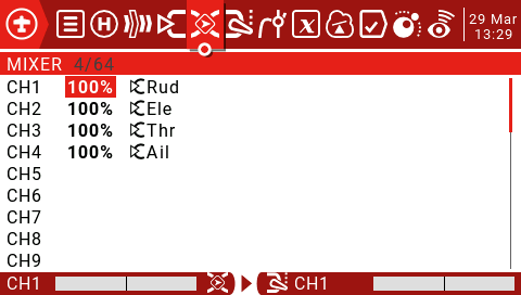
Use the scroll
wheel to select the mix list, press and hold the ENT key to enter the edit
submenu. Select Edit and short press the ENT key.


Mix name: Use the scroll wheel to select letters and numbers, long press the ENT key to switch between upper and lower case. Short press the ENT key to set the next character.
Source: Long press the ENT key to open the submenu for selecting the input source by category.
Use the scroll wheel to
select the desired category, then press the ENT key briefly, then use the
scroll wheel to press the ENT key to select the sub-item.
Weight: The range is -500 /
+ 500. The default value is 100. A negative value will reverse the response.
Offset: You can add an
offset to the input value, positive or negative. The range is -500 / + 500.
Trim: The Trim parameter
“ON” works like a mix and allows the application to fine-tune the
current flight mode specific to the specified input channel. However, if the
user disables fine-tuning in the INPUTS page, the specific channel will not be
fine-tuned.
Curve:
Diff: The differential (usually lower than the aileron stroke) is used to reduce unfavorable yaw and improve steering/maneuvering characteristics. (Default = 0, range -100 to +100) Although Diff can also be used in input, it is usually used in mixing.
Expo: The default curve is Expo, which by default is 0, which means that the response is linear (ie no curve) positive values make the response weaker around 0, while negative values make the response sharper. Although available here, Expo is usually applied to the input to conform to the idea of converting in the input and to use the mixing phase to combine the signals.
Func:
If the setting is changed to Func.
(Predefined
function curve type:)
—
(mixed line always = source)
X>0
If the source > 0, the mix line follows the source.
If
source <0, mix control line = 0
X<0
If source <0, the mix line follows the source.
If
source >0, mix control line = 0
|X|
The mix line follows the source, but is always positive (also known as
“absolute value”)
f>0
If source >0, mix control line = 100%
If
source >0, mix control line = 0
f<0
if source <0, mix control line = -100%
If
source >0, mix control line = 0
|f|
If source >0, mix control line = 100%
If
source <0, mix control line = -100%
Cstm: Select the predefined custom curves numbered CV1 to CV32 (or their reverse, ie !CV1 to !CV32). After selecting the curve number, long press ENT to open the curve page. After configuring the curve, press RTN to return.
Modes: Allows you to select the flight mode that this line can activate. By default, all flight modes are active, but if the flight mode number has been blanked, the flight mode will not be activated.
Switch: The switch position (physical or logical) can be configured to enable or disable this mix line.
Warning: As long as the line is active, you can set an audible warning (1, 2 or 3 beeps).
Multiplx: The Multpx setting defines how the current mixline interacts with other mixlines on the same channel.
Add: Add to output.
Multiply: Multiplies the results.
Replace: Replace.
The combination of these operations allows for the creation of complex mathematical operations and is often considered one of the biggest benefits of using JumperTX.
Delay Up/Dn: The output response can be delayed depending on the input change. (in seconds).
Slow Up/Dn: Regarding the input change, the response of the output can be slowed down. For example, slow speed can be used to slow down the retraction driven by a normal proportional servo. The output will cover the time in seconds (in seconds) from 100 to +100%.
4.0. Outputs

Name: This name will be
displayed on the Channel Monitoring and Runaway Protection Settings page.
Subtrim: Used
to introduce an offset on the output. A common use is to transfer the
fine-tuning to Subtrims using the “Trims => Subtrims” feature at
the bottom of this page. By shifting the offset to Subtrim, you can fine tune
the button again after fine-tuning the model.

Min and Max limits: These are “hard” limits, ie. They will never be covered. Note that they are used as gain or “end point” settings, which can be extended to +/- 150% by checking the “Extended limits” option on the “Model Setup” page.
For multi-rotor and helicopter flight controllers, the minimum and maximum limits must usually be adjusted to match your remote control travel to the expected flight controller travel.
Direction: Used to reverse the servo or output direction.
Curve: Allows you to select predefined custom curves numbered CV1 through CV32 (or their reverse, ie !CV1 to !CV32). After selecting the curve number, long press the ENT key to open the “Curve” page. After configuring the curve, press RTN to return.
PPM Center adjustment: Similar to asymmetric sub trim, except that the adjustments made here will change the entire servo motion range (including hard limits). This adjustment is not visible on the channel monitor.
Subtrim mode: When set to the default value, adjusting the sub trim will only move the center of the server.
4.1. Curves (Curves)
The curve can be used to modify the control response in the input, mix or output page. Standard curves containing Expo and Differential can be used directly in these sections, and this page is used to define any custom curves that may be needed.
There are 32 curves to choose from.
4.1. Curves
The curve can be used
to modify the control response in the input, mix or output page. Standard
curves containing Expo and Differential can be used directly in these sections,
and this page is used to define any custom curves that may be needed.
There are 32 curves to choose from.

The curve can be between 2 and 17 points and can have a fixed or user-definable x coordinate.
The X value represents the input and the
Y value represents the output.

Name: For convenience, you can name the curve.
Type:
Standard: Only Y points can
be edited, ranging from -100 to 100.
Custom: Both X and Y points
are editable, ranging from -100 to 100.
Count: The number of points on the
curve, between 2 and 17.
Smooth: If checked, it creates a smooth curve from all points.
Edit Coordinates: Moves the cursor to
the X and Y coordinates.
Depending on the type selected above, this allows writing the X coordinate of the standard curve or the X and Y coordinates of the custom curve.
Press and hold the ENT key on the coordinate point to enter the submenu:
Preset: Allows selection of standard preset linear curves with slopes of -45,
-33, -22, -11, 0, 11, 22, 33, 45. These can also be used as a starting point
for more complex curves.
Mirror: The curve will be mirrored vertically.
Clear: All points will be reset.
4.2. Global Variables
Ideally, there is an adjustment value that is used in multiple places.
For example, a glider uses ailerons as flaps when landing.
Global variables can replace normal values in each Weight, Offset, Differential,
or Expo setting.
They are also specific flight modes, which avoids having to use separate mixing
lines with different values for each flight mode. This greatly simplifies the
mixing of the pages and makes them easier to understand.
By using the “Adjust GVx” option in Special Functions, you can even
adjust global variables in flight, so you can quickly optimize settings such as
double rate ratio, expo, differential, flap to elevator transform, and more. If
a pop-up is enabled (indicated by ! next to the GV tag), a pop-up window with
the variable name and new value will be displayed on the main view when the
variable is updated.
The term global means that global variables can be used to set pages for the
entire model, but not for all models. Each model has its own set of global
variables.
There are 9 global variables available.

Press and hold the ENT key
to display the edit menu and then press the ENT key briefly to open the edit
window.


Name: Set the name.
Unit: For reference only, switch between normal and %.
Precision: When switching to “0.0”, the Gvar value is divided by 10 for the logic switch. This is necessary because, for example, Thr: -100 to 100 and GVars: -1024 to 1024. When switching to “0.–“, Gvar will not be modified.
Min: For users who use button increment/decrement values, you can set the Gvar boundary.
Max: For users who use button increment/decrement values, you can set the Gvar boundary.
FM0-FM8: You can specify a value for each flight mode or set it to be the same as other flight modes. Press and hold the ENT key to switch the input value and select the flight mode in this field. When you edit a value, it increments/decrements by 1 or 0.1, depending on the Precision setting above.
4.3. Logical Switches
The logic switch is a
user-programmed virtual switch. They are not physical switches that flip from
one location to another, but they can be used as program triggers just like any
physical switch. By evaluating the input conditions for the programming of the
logic switches, they are turned on and off (logically they become true or
false). They can use a variety of inputs, such as physical controls and
switches, other logic switches, and other sources such as telemetry values,
channel values, timer values, or global variables. They can even use the values
returned by the LUA model script.

There are up to 64 logical switches, each with three types of
operators:
Arithmetic operations either
compare two variables “a” and “b” or compare one variable
“a” with a constant “x”. Variables can be of any source,
such as hardware sources, logic inputs, mixed channels, 9 global variables, or
telemetry values. The constant “x” is the value to be compared when
the input V2 is set.
Logical operations can be
performed on binary inputs (such as hardware sources or logic inputs) and
include logical AND, OR, and XOR functions.
The difference operation
compares the magnitude of the change in the variable “a” with another
value “x”.
Functions
a=x: If the value of the
selected source “a” (V1) is “accurate” equal to
“x” (V2) (programmed value), the condition is True. Care must be
taken when using “Exact” equals the function. For example, when the
test voltage is equal to the 8.4v setting, the actual telemetry reading may
jump from 8.5V to 8.35V, so the logic switch never opens if the condition is
never met.
a~x: If the value of the
selected source “a” (V1) is approximately equal to (within about 10%)
to “x” (V2), the programmed value, the condition is True. In most
cases, it is best to use an approximation equal to a function instead of
“exact” equal to a function.
a>x: If the value of the
selected source “a” (V1) is greater than “x” (V2), the
condition is True, which is the programmed value.
a<x: If the value of the selected source “a” (V1) is less
than “x” (V2), the condition is True, which is the programmed value.
|a|>x: If the absolute
value of the selected source “a” (V1) is greater than “x”
(V2), the programmed value, the condition is True. (Absolutely means that
“a” is ignored or not, and only that value is used).
|a|<x: If the absolute
value of the selected source “a” (V1) is less than “x”
(V2), the programmed value, the condition is True. (Absolutely means that
“a” is ignored or not, and only that value is used).
AND: If both sources selected
in V1 and V2 are true (ie ON), the condition is True.
OR: If any of the selected
sources in V1 and V2 is true (ie ON), the condition is True.
XOR: If the V1 source or V2
is true (ie ON) instead of both, the condition is True.
Edge: is a momentary switch
(lasting about 30 milliseconds) that turns True when its V1 source is
triggered.
V1: The value of the selected
trigger source.
V2: Divided into two parts
, t1 is the minimum value, and t2 is the maximum duration of V1. The
logic switch becomes True only after the trigger V1 is true at least t1 and is
released before t2.
If t2 is reserved as
“—” then only t1 is applied. When V1 transitions from True to False
(ie, falling edge), the logic switch is triggered and the logic switch will be
TRUE for 1 processing cycle (~30ms). If t2 is set to “<<“, the
logic switch (ie the rising edge) will be triggered when V1 transitions from
False to True.
If the AND Switch parameter
is used, the AND switch must be True to trigger the Edge function. If the AND
switch changes to False when the Edge function is activated, the LS will not be
reset but will be timed out.
a=b: If the value of the
selected source “a” (V1) is “accurate” equal to the value
of the second selected source “b” (V2), the condition is True. Care
must be taken when using the “Exact” equal function. For example,
when comparing two voltages, the actual telemetry readings may be 4.5V and
4.55V in one scan, and jump to 4.54V and 4.45v on the next scan, so the
condition is never met and the logic switch never turns on. .
a>b: If the value of the
selected source “a” (V1) is greater than the value of the second
selected source “b” (V2), the condition is True.
a<b: If the value of the
selected source “a” (V1) is less than the value of the second
selected source “b” (V2), the condition is True.
Note: It can be seen that the
main difference between “b” and “x” in a function is to
select “a” and “b” to define the source, and “x”
is a programmed value or constant.
d>x: The condition is true
if the value of the selected source (V1) changes “d” greater than the
programmed value “x” (V2).
|d|>x: If the absolute value of “| d |” is changed, the condition is True in the selected source (V1), greater than “x” (V2), a programmed value. (Absolutely means to ignore whether a is positive or negative.)
Timer:
The logic switch is turned on and off continuously. It turns on time (V1) and
turns off time (V2).
Sticky:
When V1 switches from False to True, the Sticky function is locked (ie becomes
True) and its value is maintained until it is forced to False when V2 switches from
False to True. This can be gated by the optional AND Switch parameter on the
same line. This means that if the AND Switch condition is True, the logic
switch output will follow the conditions of the Sticky function. However, if
the AND Switch condition is False, the logic switch output remains False.
Note
that the Sticky function continues to run even if its output is gated by the
AND switch. Once the AND switch condition becomes True, the state of the Sticky
function switches to the LS output.
AND
Switch: The AND Switch provides the final logical condition to be met. The
selected function is first evaluated on V1 and V2, and then the AND Switch
condition is applied to the result. If the AND Switch condition is False, the
logic switch will never turn on.
Conversely,
the LS can only be turned on when the remaining switching conditions are True,
and the AND switch condition is also True. This is important, especially the
Sticky feature.
Any
physical, fine-tuning or logic switch flight mode can be selected for the AND
Switch.
Note
that if the AND switch condition then becomes false, it will not reset the LS
and the LS will remain on until other conditions cause it to close.
Duration:
—
or 0.0: The logic switch does not time out, but remains open until the
condition causes the switch to close.
0.1-25s:
The length of time that the logic switch will remain open, after which the
switch will turn off, even if the condition is still true.
Delay:
This is the delay time before the switch is turned on after the condition is
true. The range is from 0.0 to 25 seconds.
4.4. Special Functions
Combining logic switches with special features and telemetry opens up exciting new features for JumperTX. For example, a change in telemetry data of the receiver battery voltage returned from the model can trigger a voice alert. One of the more complex applications written using Lua scripts uses GPS sensors as timers for drone games, which can store games and circle data for analysis on a computer.
Special features include:
Override – Forces the channel output to a specific value.
Control coaching functions.
Set and reset the timer.
Reset the telemetry value.
Adjust global
variables – Allows neat features, such as optimizing settings in flight.
Adjust the
volume.
Play sounds,
tracks, background music and/or vibration (tactile) feedback.
Run the Lua
script.
Adjust the screen
backlight.
Save the
screenshot to the SD card.
Control data
logging.
Record the
position of the joystick as a fine-tuning setting to store your runaway
protection settings.

Each model can have 64 special features. In addition, there are 64
global features available for standard features of all models. These can be
accessed from the “Radio Setup” section.
Switch:
This can be any
physical switch or fine-tuning at any location, 64 logic switches, ON (always
enabled), One (trigger only once) and 9 flight modes.
Press and hold the ENT key to enter the
submenu that displays the source by category. Scroll up or down to select the
desired category, then press the ENT key.

Then you can scroll up/down from there and press ENT to select the
source.
Function:
The following functions
are triggered by the switch selected above.
Override: Forces the selected channel output (CH1 to CH32) to be a specific value between -100 and +100. This checkbox enables or disables this line.
Caution: This function
does not consider the minimum/maximum value and direction specified in the
output menu, so the servo may be overdriven.
Trainer:
“—”
Enables the coach mode on all four channels.
Rud/Ele/Thr/Ail:
Allows coach mode to be enabled only for selected controls. The checkbox
enables or disables this line. Add an SF for each control.
Inst.Trim: This
function adds the current joystick position to the corresponding trim value
when the selected switch is activated. It’s best to assign it to a switch that
you can easily reach, and then use it to quickly set up fine-tuning when flying
in a straight line and horizontally. This setting should be removed or disabled
after the flight is completed to avoid accidentally turning the switch back on
and tuning the fine-tuning. Check the box to enable or disable this line.
Reset: When the
selected switch is activated, the following will be reset (depending on the
selected option):
Timer1,2,3: The selected timer value is reset to the value set by the time parameter in the Model Settings screen.
Flight: Reset
telemetry and timers.
Telemetry: Reset
all telemetry values.
Sensor: Allows
selection of active sensors so that they can be reset individually, for
example. VSpd, Alt, Cels, RSSI, RxBt, Cmin, Cmax.
Checkbox: Enable/disable this line.
Set: Time1, 2, 3: This function
will preset the selected timer (00:00:00). Check the box to enable or disable
this line.
Adjust: Allows adjustment of
global variables (GV1 to GV9).
There are four options
for “—“:
Value (between -500 and +500)
Source (normal control range)
GVAR, another global variable

Checking “—” and long-pressing the ENT button will bring up a pop-up menu that allows you to choose between Constant, Global Var and Increment / Decrement.
If you press the ENT key on
any of the four source types, Constant, Mixer Source, Global Var or
Increment/Decrement, it will pop up a pop-up menu that allows you to choose
between the other three types.

Pressing the ENT
key while the mixing source is active will display the submenu of the source by
category. Scroll up/down to the desired category and press the ENT key. It
takes you back to the parameter being edited on the first item in the selected
category. Then you can scroll up/down from there and press ENT to select the
source.

Checkbox: Enable/disable
this line.
Volume:
The selected source will adjust the volume. A simple app will use the knob to
control the volume. Check the box to enable or disable this line.
SetFailsafe
Int.Module: Allows dynamic setting of runaway protection on the ground or in
the air. Set the control interface to runaway protection and press the selected
switch to store the runaway protection value. This feature is available for
internal XJT modules. The checkbox enables or disables this line.
SetFailsafe
Ext.Module: As mentioned above, but for the external module of the emitter. The
checkbox enables or disables this line.
Play
Sound: Any simple sounds listed in the drop-down parameter box will be played.
!1x:
Play the sound once, not at startup.
1x:
Play a sound once.
1s-60s:
Repeats the sound at the specified interval.
Play
Track: Play any .wav sound file stored on the SD card. The list of available
sounds will be displayed in the parameter column of the drop-down box.
!1x:
Play the sound once, not at startup.
1x:
Play a sound once.
1s-60s:
Repeats the sound at specified intervals.
Play
Value: Say the value of any controls available in the parameter menu. These can
include switch or joystick values, or telemetry values or time.
Select “—” and
press and hold the ENT key to pop up the menu showing the source by category.
Scroll up/down to the desired category and press ENT, which takes you back to
the special features page with the cursor on the first item in the selected
category. Then you can scroll up/down from there and press ENT to select the
source.
!1x:
Play the sound once, not at startup.
1x:
Play a sound once.
1s-60s:
Repeats the sound at specified intervals.
Lua Script: This field is used for function typescripts that run on-demand using this special feature. The script should be placed in the /SCRIPTS / FUNCTIONS/folder of the SD card.
Background
Music Pause: Pause the background music. Play music when the source is enabled,
pause when disabled. Resume playback when re-enabled.
Vario:
Vario only sounds when the specified switch is enabled.
Haptic:
The vibration function needs to be enabled in RADIO SETUP.
Intensity:
0-3
!1x:
Vibration once, does not vibrate when turned on.
1x:
Vibration once.
1s-60s:
Repeat the vibration at the specified time.
SD
Logs: Sets the frequency (in seconds) at which the data records are sampled and
stored on the SD card.
“—”
does not create a log.
0.2-25.5s:
Log records are saved at specified intervals.
Backlight:
This parameter displays a slider that sets the level of the screen backlight.
Used to conserve battery power or to compensate for different lighting
conditions.
Press and hold the ENT key on a defined special function to bring up a menu to copy, insert or clear the function.

4.5. Custom Scripts
Custom scripts allow you to
modify the behavior of the remote to add specialized features to your custom
tasks. The scripting language used is Lua, a lightweight, embeddable scripting language
designed to be used from games to games.
Various applications for web applications and image processing, in this
case for implementing custom functions in the radio. There are three basic
types:
One-time: The script only runs once
and then terminates. For example, the receiver and flight controller setup
scripts, as well as the new Create Model Wizard. They are executed from the
/SCRIPTS/folder on the SD card.
Mix: The script becomes part of the
control loop in the radio and runs repeatedly. These are set using this custom
script page. They usually read one or more values, do some processing on them,
and then output one or more values. These scripts should be as short as
possible, because exceeding the script execution runtime limit will cause the
script to be forced to stop and disable.
Function: Scripts run on demand
using special features, usually triggered by events or switches.
There are some caveats – if the
script stops executing, you should never use Lua model scripts to control any
aspects of the model that might cause a crash. The reason is that if the script
tries to use too much CPU time or memory, it will be shut down and will not run
again when the model is selected.

The Custom Scripts page is used for mixed-type scripts that run continuously. These scripts should be placed in the SD card / SCRIPTS / MIXES/folder.
Up to 9 custom scripts

You can select a script in
the first line and optionally define a custom name to know what to use in the
second line. The screen also displays the inputs and outputs used by the
script.
The basic layout of Lua scripts
The user-written Lua script is basically a subroutine called by the main loop of the remote control code. A subroutine is a block of code that can be called to perform a task when needed and then return control to the calling code. A custom Lua script can contain four basic subroutines (input, output, initialization, and run), three of which can be optional. You must define these four subroutines in the return statement at the end of the script.
Input: This is usually how the
script gets the information passed to it. The Input subroutine is optional and
not required.
Output: This subroutine defines the variables that the script will return. It allows you to return up to seven values, which can only number for this stage. The output is also optional and not required.
Init: This subroutine is used to
initialize the script. You should set an initial value for the variable and
perform any preparations. The subroutine runs once each time the model is
selected or the remote is turned on when the model is activated. This
subroutine is also optional and not required.
Run: This is where the work of the Lua script is done. It can be compared to main() in languages such as C# or Java. As those languages, variables can be passed to it. This routine will return the variables defined in the Output subroutine.
4.6.
Telemetry
JumperTX supports a very comprehensive data transmission system for Frsky and third-party sensors.
Smart
Port telemetry(S.port)
Through this connection, the
receiver can achieve full-duplex (bidirectional) high-speed communication.
main feature:
Each value received through a
digital transmission is treated as a separate sensor with its own attributes.
Multiple identical sensor types can be connected, but the physical ID must be
changed. For example, sensors for each of the 2 – 6S lithium batteries, or monitor
individual motor currents in a multi-motor model. Each sensor can be
individually reset by special functions.
The digital sensor can:
Play the value by voice.
Used for logic switches.
Input for proportional operation.
Displayed in the custom data
transfer screen.
sensor type:
RSSI
Receiver Signal
Strength Indicator (RSSI): The value transmitted by the receiver in the model
to the remote control, indicating the strength of the received signal. Warnings
can be set to warn below the minimum value, indicating that you are out of
range. Factors affecting signal quality include external interference,
excessive distance, poor orientation, or antenna damage.
It is not an absolute
measurement, but a number that represents the ratio of the signal to some
initial “good” value. This number is relative, but can indicate that
the model may be close to the range limit of the control aircraft.
When the return signal
is completely lost, the remote controller will have a “return signal
lost” prompt. Please note that due to a fault in the return link, the
remote can no longer warn you of RSSI or any other alarm condition, so no
further beep will sound.
Digital transmission settings:
RSSI:
Low Alarm: Range
15-75, default 45.
Critical Alarm: Range
12-72, default 42.

Sensors:
Discover new sensors:
Short press the ENT key to find a new sensor for the first time.
Stop Discovery: Short
press the ENT key to stop discovering the sensor.
Delete all sensors:
This option will delete all sensors so that you can start adding sensors again.
Ignore instances:
Normally, you will see a pop-up window showing “all telemetry slots are
full” and you will not be able to close. Turn off the receiver, then close
the pop-up window, enter the telemetry screen and delete the duplicated items.
Then check this option to prevent this sensor from repeating errors.

All found sensors are
automatically displayed during the discovery process. If no S.port sensor is
plugged into the receiver, only the sensor that comes with the receiver can be
found and set.
Add a new sensor: Allows you to manually add new sensors. Short press the ENT
key to call up the Add New Sensor menu.

Name:
Set the name.
Type: Available with Custom and Calculated.
Custom sensor settings:
Type: Custom
ID: Sport ID number (4-digit hexadecimal), usually read from the sensor. The second
field is the physical ID number to be entered.
Unit: V, A, mA, kts, m/s, f/s, kmh, mph, m, ft, degC, degF, %, mAh, W, dB, rpm,
g, deg, ml, fOz
Precision: Shift the decimal to 0 or 0.0 or 0.00.
Ratio: “-” 0-3000.0.
If
Ratio is “-“, the telemetry value is calculated as follows: (sensing
value divided by 10)
(received
value/10) + Offset=displayed value
Or,
if Ratio is not “-“, the telemetry value is calculated as follows:
[(received
value / 255) * Ratio] + Offset = displayed value
The
ratio allows the received sensor values to be corrected or converted, for
example between km / h or between sections.
Offset:
between -3000 – +3000.
Auto Offset: When checked, it will be automatically reset to zero. For example, when the Vario sensor is at ground level when the power is turned on, it stores the first value received after reset as zero. This provides an “AGL” reading instead of an “above sea level” reading.
Positive:
Limit any negative value to zero.
Filter:
When selected, the moving average of 4 past values will be calculated.
Logs:
If checked, the SD card will be logged. Please note that the log record must
still be started by the Special Function. This option only makes the data
available for recording.
Calculate
sensor settings:
Type:Calculated
Formula:
Add,
Average, Multiply: Values can be added, averaged, or multiplied.
Min,
Max: You can extract up to or up to a set of 4 values.
Totalize:
This function adds each value as it is received.
Consumption:
This value will be integrated over time.
Unit:
“-“, V, A, mA, kts, m/s, f/s, kmh, mph, m, ft, degC, degF, %, mAh, W,
dB, rpm, g, deg, ml, fOz
Precision:
Shift the decimal to 0 or 0.0 or 0.00.
Source1-Source4:
Select from any active sensor.
Auto
Offset: Automatically resets to zero when checked.
Positive:
Limit any negative value to zero.
Filter:
When selected, the moving average of 4 past values will be calculated.
Persistent: When selected, this value is retained during a power outage and resumes during power-up. Very useful for functions such as mAh consumption.
Logs:
If checked, the SD card will be logged. Please note that the log record must
still be started by the Special Function.
Professional
features:
Lithium
battery cell voltage:
The Lipo voltage sensor FLVSS
adds the following parameters to the list:
Cels: Total battery voltage.
In order to get a single battery voltage, a new calculation sensor needs to be
defined.
Name: Cmin or Cmax.
Type: Calculated
Formula: Cell
Cell sensor: Select from active
Lipo voltage sensors, for example, Cels.
Cell Index: lowest, 1, 2, 3,
4, 5, 6, highest.
Log: If checked, it will be
logged to the SD card. Please note that the record must still be started by the
Special Function.
Distance:
The GPS sensor
adds the following parameters to the list:
GPS: Longitude and
latitude.
Galt: Height.
GSpd: Speed.
Date: Date, time.
To get the distance from the
GPS power-up position to the current position, define a new calculation sensor.
Name: Dist
Type: Calculated
Formula: Distance
Unit:m
GPS sensor: Set
this to “—” and we do not use height values for this calculation.
Alt sensor: Select
the “Galt” entry from the list of activity parameters.
Logs: If checked, it will be logged to the SD card. Please note that the record must still be started by the Special Function.
Current sensor 40A
The 40A current
sensor adds the following parameters to the list:
Curr: Current
To get the consumption
(battery in mAh), define another new calculation sensor:
Name:
Type: Calculated
Formula: Consumpt
Sensor: Curr
Unit: mAh
Persistent: When selected, this value will remain during power down and resume during power-up.
Logs: If checked, it will be logged to the SD card. Please note that the record must still be started by the Special Function.
Variometer settings:
The Vario sensor adds the Vspd and Alt parameters to the sensor list.

Source: To enable Vario, set “VSpd” as the source on the main telemetry page under the “Variometer” heading.
Range: Sets the maximum expected sink rate (-17 to -3, default -10m/s) and the maximum rate of climb (3 to 17 and defaults to 10m/s) for the sounds generated by the Vario custom function.
Center: Sets the sink/climb rate limit for the center “dead zone” (-2.1 to 0.5, default -0.5 and -0.5 to 2.0, default is 0.5m/s). Replace “Tone” with “Silent” to turn off the tone in the center range.
If you want to use the switch to open and close Vario as shown below.

4.7.
Simple delta wing setup example
JUMPER T16 можно сказать ворвался на рынок и сообщество FPV пилотов точно будет в восторге, а следом и обновленный JUMPER T16 PRO. Эта аппаратура предлагает множество функций по сравнительно низкой цене и Frsky Taranis X9D с QX7 наконец-то столкнулись с настоящим конкурентом.
Источник: oscarliang.com
Аппаратура управления квадрокоптером, какая бывает и как выбрать
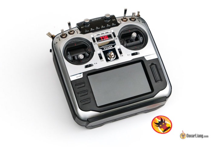
Содержание
- Характеристики и особенности
- Основные технические характеристики
- Что в комплекте?
- Внешний вид JUMPER T16
- Экран, кнопки и пользовательский интерфейс
- Стики (гимбал)
- Переключатели
- Внешний модуль
- Аккумуляторный отсек и SD-карта
- Полеты в FPV симуляторе на Т16
- Программное обеспечение
- Первое впечатление
- Размер и вес
- Механизмы стиков (гимбал)
- Сравнение с Taranis
- Jumper T16 против Jumper T12
- Плюсы и минусы Jumper T16
- Скоро будут еще тесты этой аппаратуры
- Видео
- Часто задаваемые вопросы (FAQ)
- JUMPER T16 PRO
- Чем отличается JUMPER T16 от JUMPER T16 PRO?
Характеристики и особенности
Jumper очень амбициозные ребята, цитирую их письмо:
…создать самую высокопроизводительную аппаратуру управления с открытым исходным кодом на сегодня. Т16 ЕДИНСТВЕННАЯ аппаратура, чтобы управлять всеми…
Что заставляет их быть такими уверенными? Ответ ниже:
- Большой цветной LCD-экран 4,3 дюйма (480*272px);
- Съемный аккумулятор — для пульта нужны 2 аккумулятора типа 18650 или один LiPo 2S;
- Пульт поддерживает съемные модули, например, TBS Crossfire и Frsky R9M;
- Есть многопротокольный модуль, то есть, поддерживаются приемники Frsky, Flysky и другие!
- Работает на OpenTX (формально JumperTX);
- Голосовые уведомления;
- Обратная связь с вибрацией.
Почти все тоже самое, что делает X9D-Plus, но значительно дешевле, цена примерно около 150$ (около 10 тысяч рублей на момент публикации).
Основные технические характеристики
- Работает на процессоре STM32F429BIT6 (MCU);
- Входное напряжение: 7-8.4V;
- Потребляемый ток: 350 mA без внешнего модуля;
- Размер: 180*190*58
- Вес: около 860 грамм.
Что в комплекте?
JUMPER T16 поставляется со следующими аксессуарами:
- Мини USB-кабель;
- Ремешок для шеи;
- Запасные части для механизмов стиков (гимбал) — возвратные пружины и другое;
- Защита экрана.
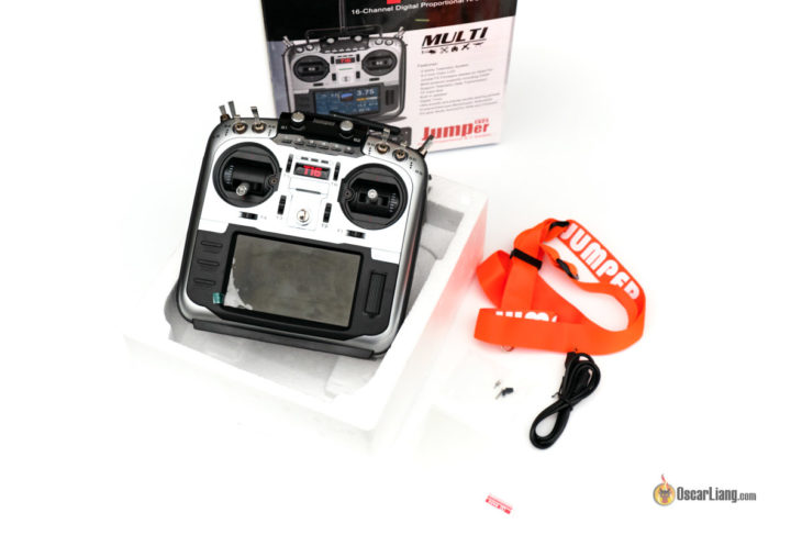
Что уже установлено в аппаратуре:
- SD-карта на 512 МБ;
- Держатель для аккумуляторных батареек 18650;
- Многопротокольный модуль JP4-in-1;
- Почему то нет инструкции, надеюсь, они это исправят.
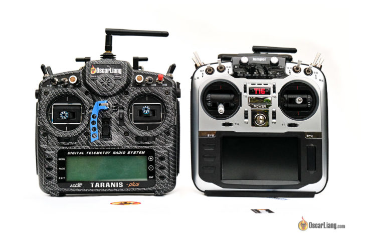
Когда я взял Т16 в руки, то был приятно удивлен его формой и размерами, это уже не просто игрушка, как Т8 или Т12.
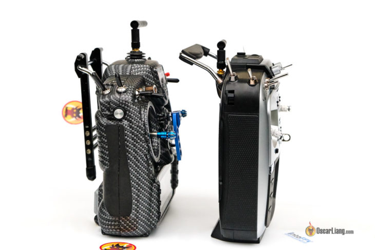
Т16 немного выше X9D, но тоньше него.
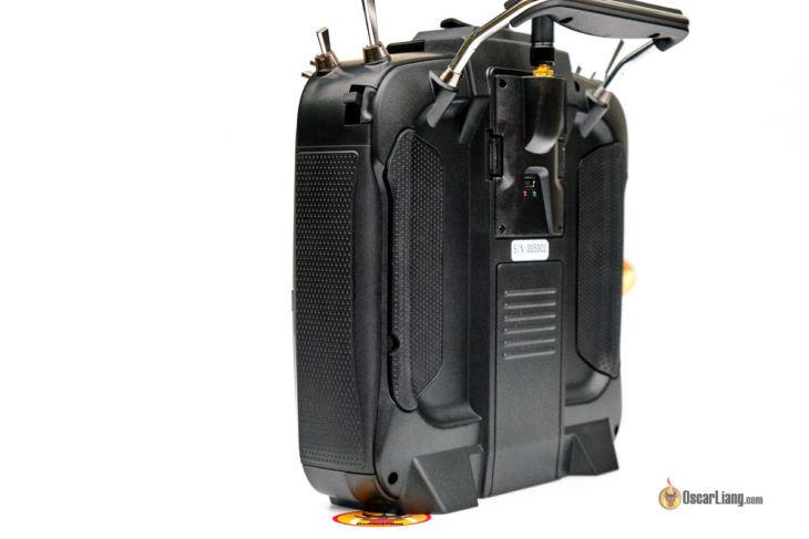
Задняя ручка сильно выпирает и занимает много места, когда вы кладете пульт в рюкзак. Резиновые накладки по бокам приятные на ощупь.
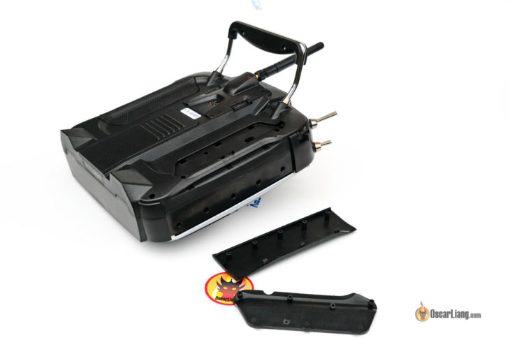
Также, эти накладки снимаются, может быть, что-нибудь придумаю и напечатаю на 3D принтере другие.
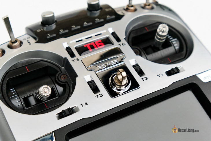
По центру пульта расположен крючок для крепления шейного ремешка. При использовании ремешка, аппаратуру не требуется центрировать и балансировать, она идеально висит на ремне.
Чтобы включить пульт, нажмите и удерживайте 5 секунд кнопку питания. При включении загорится светодиод. То же самое делается и для выключения. Принцип включения похож на QX7 и Horus X10S. Я думаю, что это отличное решение, нежели тумблер у X9D, потому что он иногда сам передвигается в сумке при переноске.
Экран, кнопки и пользовательский интерфейс
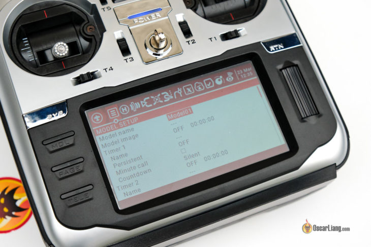
Этот большой цветной экран просто потрясающий! Такой же экран установлен в Horus X10S за 420$. Обратите внимание, что это не сенсорный экран. Сенсорный экран есть у Flysky Nirvana, это круто, но я предпочитаю использовать кнопки, потому что это точнее.
Пользовательский интерфейс идентичен Horus X10S в OpenTX и если вы уже знакомы с QX7 или X9D, то интерфейс не будет вызывать у вас вопросов.
С левой стороны экрана расположены 4 кнопки: SYS (настройки), MDL (модель), PAGE (страница) и TELE (телеметрия):
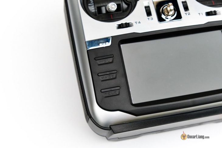
А с правой стороны: RTN (возврат/отмена) и кнопка-ролик — эта штука очень проста в использовании! Немного похоже на кнопку на зарядном устройстве iSDT Q6. Ролик крутит по списку вверх и вниз, но расположен вертикально, что не интуитивно и неудобно:
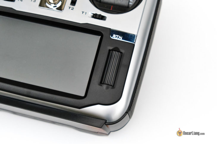
Стики (гимбал)
Я думаю, что механизм стиков это простой подвес-потенциометр, а не «датчик Холла» — я объясню это в главе Первое впечатление).
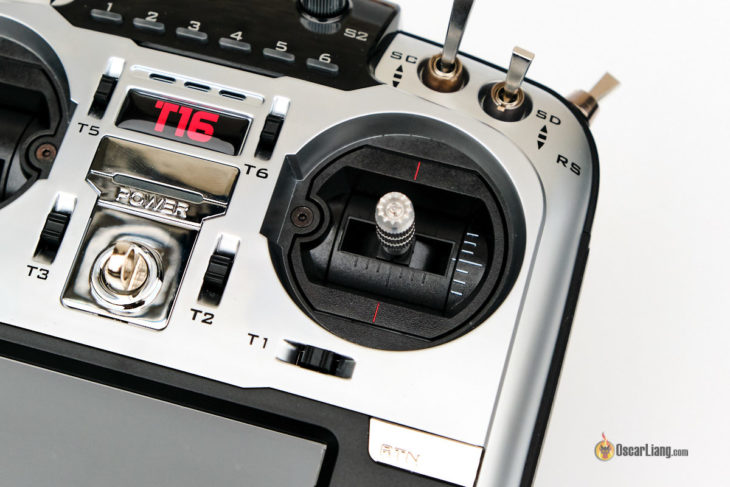
Рядом с каждым подвесом есть винт М2, который поднимает одну сторону вверх или вниз, поэтому вы можете отрегулировать наклон точно под себя. Очень классная особенность, я такого еще не видел.
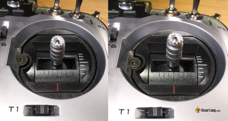
Высота стиков регулируется, а также можно менять насадки, диаметр резьбы — 3 мм, то есть, М3.
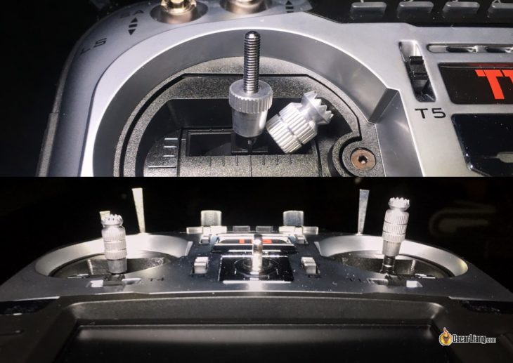
Мой Jumper T16 в режиме 2, то есть, throttle/yaw (газ и рыскание) — слева, а pitch/roll (тангаж и крен) — справа. Но вы можете поменять этот режим, если вам нужно по другому.
На пульте есть 6 триммерных (щелкалки) кнопки, 4 для подвесов стиков и 2 запасные (Т5 и Т6) для программирования (то есть, вы им можете назначить действие).
Переключатели
На пульте столько же разных переключателей, как и на Taranis X9D-Plus. Этого должно быть достаточно для большинства пилотов и тем более для мини-квадрокоптеров.
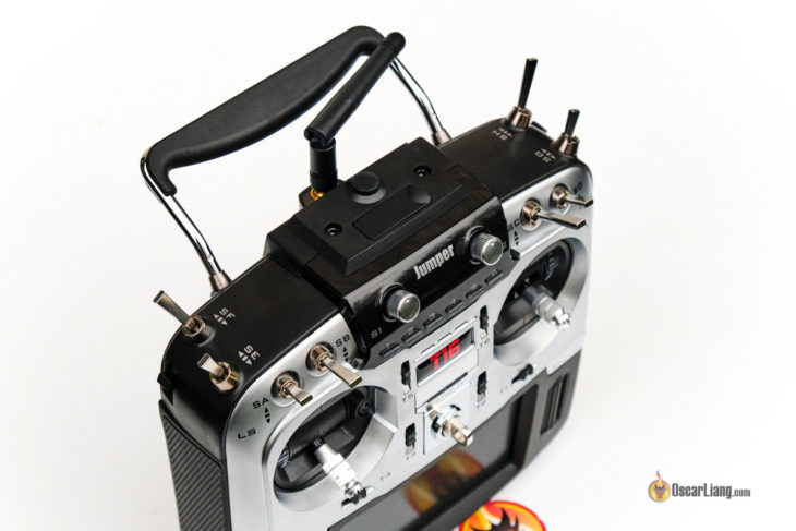
В общей сложности 8 переключателей, 6 из них трехпозиционные и 1 мнговенный. 2 пота (потенциометр или горшки, говоря по простому) и 2 ползунка, по одному с каждой стороны.
Для мини-квадрокоптеров потребуется всего 2-4 переключателя, а большее количество обычно используется для пилотов самолетов и монокрыльев.
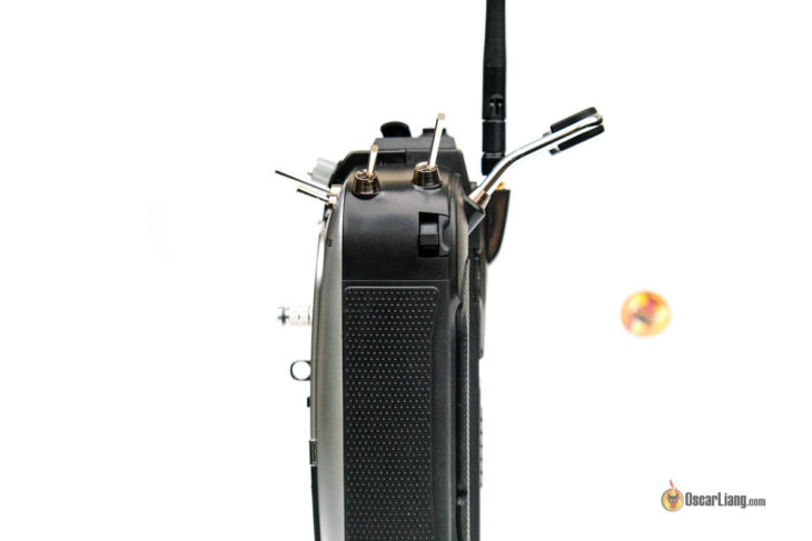
Под горшками в верхней части есть еще 6 кнопок, от 1 до 6. Это функциональные кнопки, думаю, что они нужны для режимов полетов в современных полетных контроллерах, таких как APM и Pixhawk.
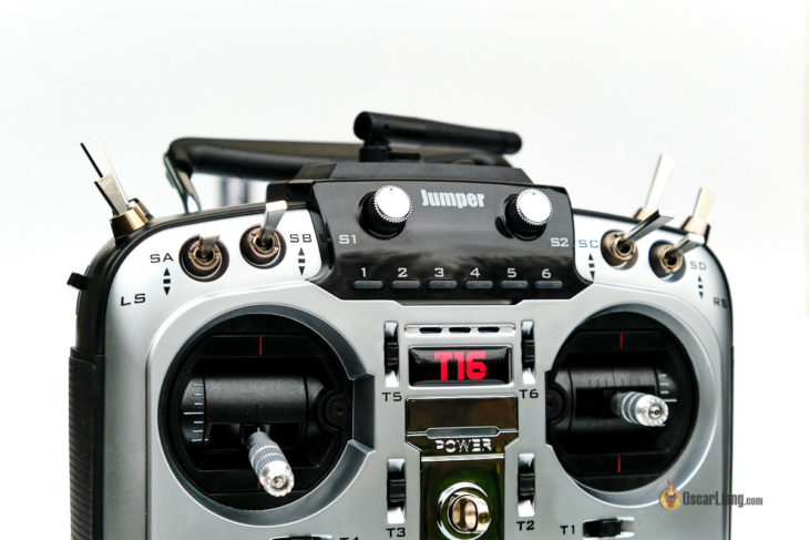
Внешний модуль
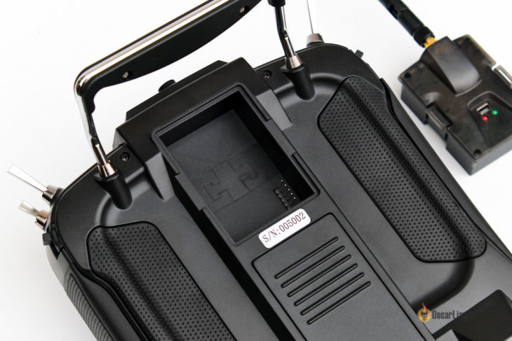
На задней стороне JUMPER T16 есть отсек для внешних модулей JR, таких как R9M и Crossfire.
Как и у младшей версии, у Т16 нет встроенного модуля RF и он предполагается как внешний модуль. По этому причине, у Т16 есть встроенный модуль Multi-Protocol JP4IN1.
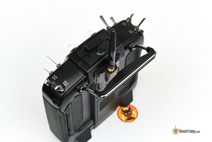
JP4IN1 это очень мощный модуль, потмоу что поддерживает многие популярные радиочастоты, включая FrSKY, Flysky, Hubsan и другие. Это значит, что если у вас в дронах стоят приемники FrSKY, Flysky или Hubsan, то проблем не будет и они будут реагировать на пульт.
Протокол можно поменять в меню настроек модели.
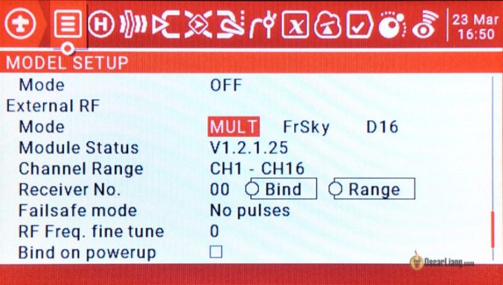
Список поддерживаемых протоколов:
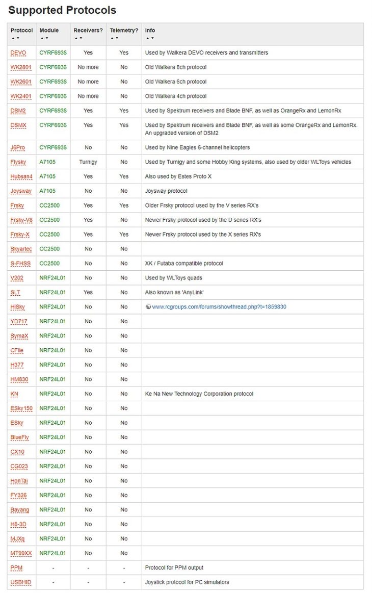
Обратите внимание, что модуль JP4in1 выглядит немного иначе, чем модуль в T12.Они убрали поворотный переключатель и кнопку привязки. Но ничего страшного, потому что все действия можно выполнять в меню не используя физические кнопки. А вот порт miniUSB остался для обновления модуля P4-in-1.
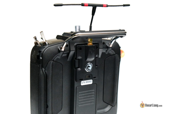
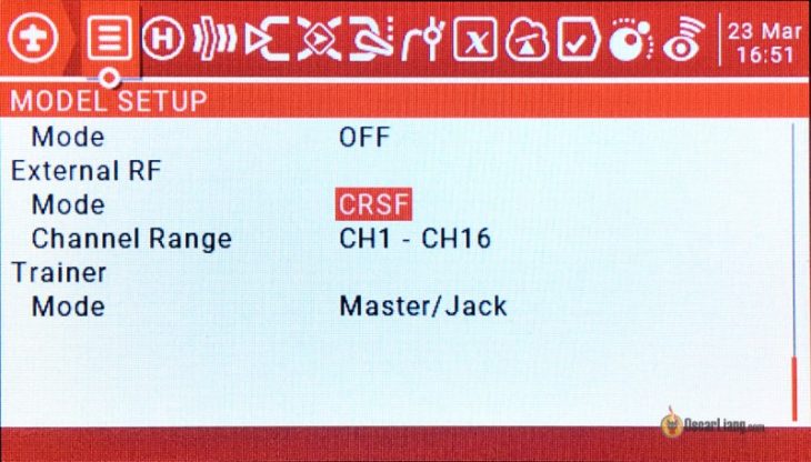
В своей рекламе, компания Jumper неоднократно заявляла, что «TBS Crossfire поддерживается прямо из коробки» и у меня вопрос, почему тогда не поддерживается «из коробки» и Frsky R9M.
Вся новая аппаратура от Frsky после X9D перестала поддерживать Crossfire. Использовать можно будет только после нескольких модов. Многие предположили, что это шаг вперед для собственной дальнего радиуса действия 900 МГц — R9M.
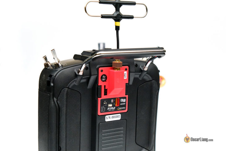
Аккумуляторный отсек и SD-карта
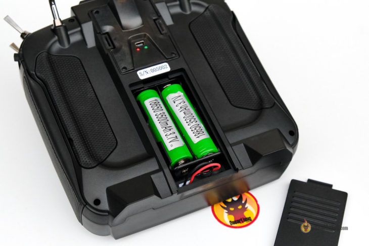
Jumper T16 поставляется со специальным держателем аккумуляторов 18650, но их самих в комплекте нет.
Вы также можете использовать 2S LiPo. Размер аккумуляторного отсека составляет 75x42x16 мм.
Одна небольшая проблема все таки есть с этим отсеком — он неплотно прилегает и по этому гремит внутри. Это можно исправить куском фольги, но Jumper уже сказали, что исправят это, так что, скорее всего у вас уже не будет этой проблемы.
Встроенного зарядного устройства нет и вам нужно будет извлекать батарейки для заряда.
Они могли бы приделать к держателю 18650 провода для зарядки — один разрядный провод и один балансир, но не знаю почему это не сделано, наверное для удешевления производства.
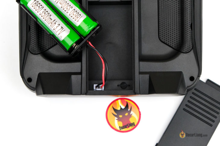
Слот для SD-карты также находится внутри аккумуляторного отсека. Но сам пульт уже продается с установленной SD-картой на 512 МБ, поэтому вам не нужно докупать ее отдельно.
Полеты в FPV симуляторе на Т16
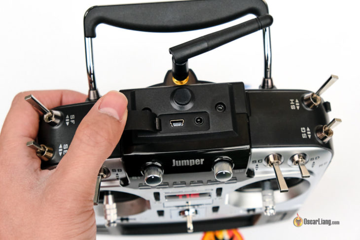
Сверху пульта, под резинкой есть порт miniUSB (почему не microUSB?), он нужен чтобы:
- Летать в симуляторе;
- Заходить на SD-карту;
- Прошивать пульт.
Я проверил, как эта аппаратура работает с симуляторами FPVAir 2 и Liftoff — все прошло отлично и работало без каких-либо настроек. Каналы отличаются от Тараниса и требуется калибровка, если вы уже летали в симуляторе на Таранисе. Если JUMPER T16 не отобразился при подключении как Джойстик, то проверьте в настройках USB — установлен ли там этот параметр.
Рядом с портом USB есть еще один разъем, который похож на разъем для наушников, но при подключении наушников они не заработали, но позже я узнал, что это порт тренера.
Программное обеспечение
Jumper T16 поставляется с очень свежей версией прошивки 2.2.3, датированной от 17 марта 2019 года.
Пользовательский интерфейс выглядит идентично прошивке OpenTX, которая работает на Horus X10S и кроме логотипа ничем не отличается.
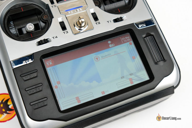
JumperTX — это ответвление OpenTX и тут все легально, прошивка официальная. Им нужно заплатить, чтобы использовать OpenTX в своих продуктах и даже если она заплатят, код все равно должен оставаться открытым.
Кстати, в настройках отсутствует моделька мультикоптера, надеюсь это будет исправлено в следующих версиях.
Jumper подтвердили, что можно обновлять прошивку через OpenTX Companion, а также с помощью SD-карты.
Первое впечатление
Размер и вес
Jumper T16 оказался в размере больше, чем я ожидал. Сначала, когда я рассматривал фото аппаратуры, я думал, что он будет меньше, чем Т8 или Т12, но оказывается, его форм-фактор больше похож на X9D или QX7, что мне нравится.
Вес тоже примерно такой же, Т16 с двумя аккумуляторами 18650 весит 860 грамм, против 870 грамм у Taranis X9D с такими же аккумуляторами.
Механизмы стиков (гимбал)
По сравнению с подвесами М9 на X9D, подвесы Т16 значительно жестче. Когда стик по центру, сопротивление больше и уменьшается к границе наклона. Но они все равно мягче, чем стоковые подвесы на Taranis.
Jumper сообщили, что они в следующих партиях будут использовать более «мягкие» пружины для повесов (для механизмов стиков).
Сравнение с Taranis
По качеству сборки он похож (внешне) на Taranis X9D-Plus.
Самым большим отличием от Тараниса, думаю, будет корпус и экран. Исходя из своего опыта использования в течение нескольких последних дней, мне все еще нравится эргономика моего Тараниса X9D, наверное дело в привычке.
Из «коробки» (после распаковки, то есть), стики немного коротковаты, но они регулируются и это не проблема, тем не менее, они не совсем идеальны для пальцев, если вы удерживаете стики двумя пальцами, а не одним, из-за расположения подвесов, потому что они расположены довольно близко к верхней части пульта, но опять же, дело привычки.
Я могу держать сам пульт и зажимать пальцами стики у Тараниса X9D, но не могу у Т16 без шейного ремешка.
Taranis X9D столкнулся с настоящей конкуренцией от Jumper T16. Стоимость не SE версии X9D (подвесы на пружинах) около 220$, в то время как Т16 стоит около 150$ + 10$ на два аккумулятора.
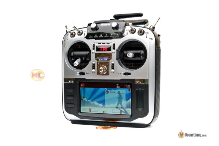
Лучше ли Jumper T16 аппаратуры Taranis QX7? Я бы сказал, что это определяется особенностями, если вы ищете дешевую и качественную с множеством функций аппаратуру, то Т16 на сегодня нет равных.
Т16 это надежная аппаратура, но я сомневаюсь насчет эргономики. Если они смогут улучшить захват для пинчеров (тех, кто двумя пальцами держит стик), то этот пульт будет явным лидером.
И, наконец, я хотел бы, чтобы у аппаратуры был встроенный RF-модуль 4 в 1, чтобы вам не нужно было его менять каждый раз, если захотите использовать R9M. Но я думаю, что это ограничение из-за прошивки, чтобы избежать больших изменений в программном обеспечении.
Jumper T16 против Jumper T12
Jumper T12 может делать почти все тоже самое, что и Т16: поддерживает внешние модули JR, работает на прошивке OpenTX. Но Jumper T12 все равно не был достаточно конкурентноспособыным, это мое мнение.
T12 — отличная аппаратура, но похожа на игрушку — маленькие подвесы, и мне не понравилось, как они держатся в руках, по этой же причине не понравился и X-Lite.
Думаю, что те, кому нравится Т12, выбирают пульт из-за меньшего размера и меньшей цены, ведь это всего 90$.
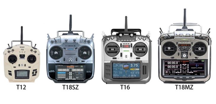
Плюсы и минусы Jumper T16
Большой и цветной экран, он мне очень нравится
Удобные кнопки меню
Поддержка аккумуляторов как 18650, так и LiPo 2S
Большие подвесы (гимбалы), хорошее качество для такой цены
Много переключателей и тумблеров + 2 «горшка», а также 6 кнопок для смены режимов полета
Поддержка Crossfire и других внешних модулей JR
Продается с многопротокольным модулем RF — поддержка приемников Frsky, Flysky и других
Цена всего 150$
И самое главное, теперь есть конкуренция на рынке аппаратуры управления
Не на 100% подходит для пинчеров (те, кто держат стик двумя пальцами), если не использовать шейный ремешок
Нет подвесов Холла
Задняя ручка занимает много места
Держатель аккумуляторов 18650 не предназначен для зарядки, нужно вытаскивать батарейки
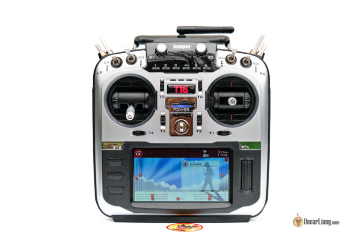
Скоро будут еще тесты этой аппаратуры
И так, закончен первый обзор Jumper T16, надеюсь, вам понравилось! В ближайшие несколько недель, я буду проводить еще тесты и проверять надежность, об этом будет написано здесь.
Что еще нужно протестировать:
- Какой диапазон при использовании протокола Frsky с приемниками XM + и R-XSR?
- Как обстоят дела с R9M по сравнению с Taranis X9D?
- На сколько хватает аккумуляторов 18650?
- Все ли популярные функции OpenTX работают должным образом, например, скрипт LUA, специальные функции и т. д.
Видео
Часто задаваемые вопросы (FAQ)
Можно ли отключить экран во время полета?
Большой цветной экран может быть достаточно энергоемким элементом. Отключить экран нельзя, но вы можете отключить подсветку и активировать ее при нажатии кнопок меню. Это хороший способ для экономии заряда аккумуляторов, как и в Taranis:
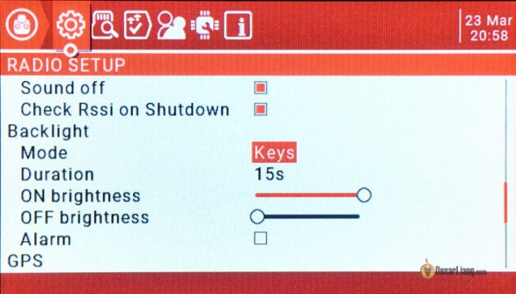
Могу ли я заменить подвесы на М7 или М9?
На данный момент сказать трудно, думаю, что это возможно с некоторой модификацией. Этот вопрос уточняется.
Можно ли регулировать натяжение подвеса (гимбала)?
Натяжение регулировать можно, я расскажу вам об этом при следующем обновлении.
Можно ли заряжать 18650 или LiPo внутри аппаратуры?
Нет, порт USB для этого не предназначен. Требуется извлекать аккумуляторы для зарядки.
JUMPER T16 PRO
Версия Jumper T16 Pro теперь включает в себя встроенный модуль RX, освобождающий задний слот для систем дальнего радиуса действия, таких как TBS Crossfire. Вместо стандартных механизмов стиков, стоят датчики Холла.
Чем отличается JUMPER T16 от JUMPER T16 PRO?
- Встроенный многопротокольный модуль с поддержкой TBS Crossfire.
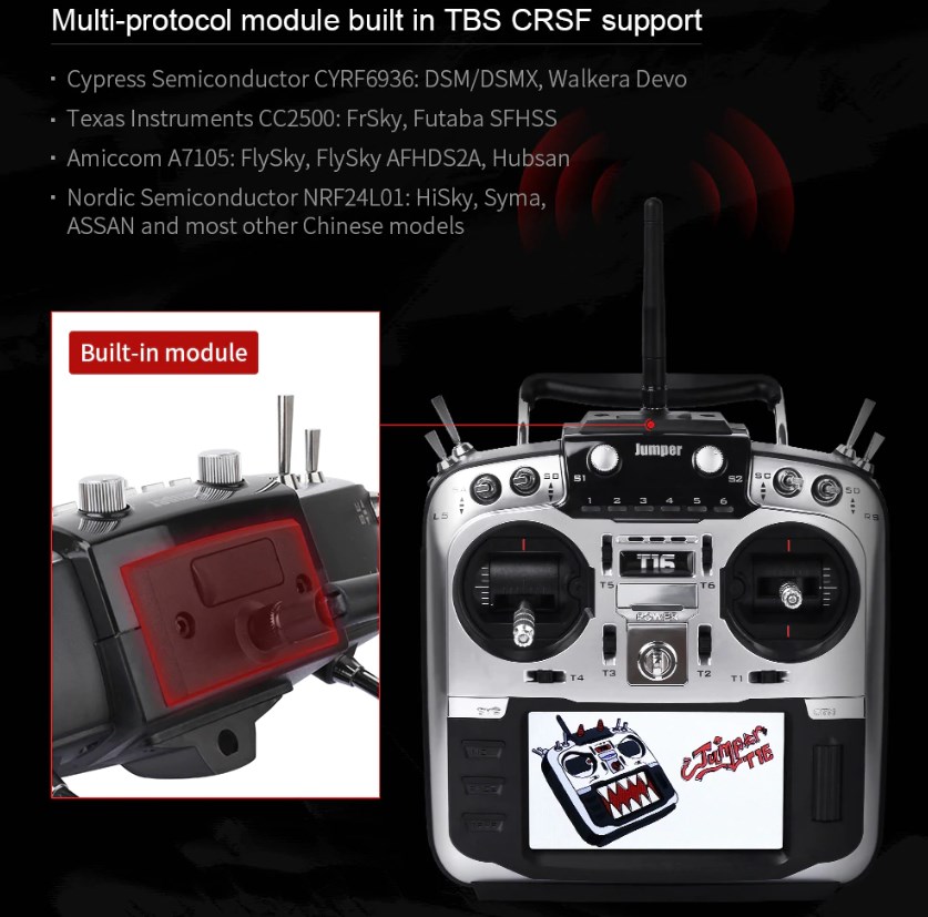
В остальном все тоже самое.
Обновлена 01.10.2019 — добавлена информация о PRO версии.
JUMPER T-PRO Gaming Sharp Transmitter and Hall Sensor Руководство пользователя
Введение
Спасибо за покупку джемпера. Радиосистема Т-про. Пожалуйста, внимательно прочитайте это руководство по эксплуатации перед использованием, чтобы обеспечить правильное и безопасное использование. В связи с обновлением версии произошли изменения. Информация, содержащаяся в данном руководстве, может быть изменена без предварительного уведомления.
Многие модели на радиоуправлении оснащены мощными моторами и остро вращающимися пропеллерами. Будьте осторожны при работе с моделями. Убедитесь, что питание ваших моделей отключено, и снимите пропеллеры при проведении технического обслуживания. Не используйте радиосистему T-Pro в следующих условиях.
- В плохую погоду или при сильном ветре, например, при дожде, граде, снеге, буре или электромагнитных явлениях.
- В любых условиях ограниченной видимости.
- В местах, где могут находиться люди, имущество, линии электропередач, дороги, транспортные средства или животные.
- Если вы чувствуете усталость или плохое самочувствие или находитесь под воздействием наркотиков или алкоголя.
- Если радио или модель повреждены или не работают должным образом.
- В местах с сильными помехами 2.4 ГГц или в местах, где использование радиостанций 2.4 ГГц запрещено.
- Когда батарея T-Pro или модель слишком разряжена для работы.
OpenTX/EdgeTX — это экспериментальная прошивка. Не дается никаких гарантий или подразумеваемых гарантий в отношении качества и надежности этой прошивки.
Неправильное обращение с радиоуправляемой моделью может привести к серьезным травмам или даже смерти. Если вы решите использовать прошивку OpenTX/EdgeTX, вы будете нести полную ответственность за свою модель.
Любые травмы или повреждения, вызванные использованием прошивки OpenTX/EdgeTX. Автор OpenTx EdgeTX не несет за это ответственности. Пожалуйста, используйте его с осторожностью.
Прошивку OpenTX можно найти здесь: https://github.com/OpenTx
Прошивку EdgeTX можно найти здесь: https://edge-tx.org
Мультипротокольную прошивку можно найти здесь: https://downloads.multi-module.org
Краткое введение

Первая загрузка
Длительно нажмите кнопку питания. Перед входом в основной интерфейс система проверит положение ручки газа и переключателя, а также другие условия запуска. Если условия запуска не соблюдены, появится соответствующее сообщение об ошибке. Пользователь должен очистить или нажать любую клавишу, чтобы пропустить.
- Предупреждение ЭСППЗУ: Неверные данные EEprom. Нажмите любую клавишу, чтобы радио автоматически отформатировало и сохранило для создания новых данных дистанционного управления. files.

- Предупреждение о переключении: Это предупреждение о том, что переключатель на радиоуправлении не находится в положении по умолчанию. (Настройкой по умолчанию является то, что все направления переключателя находятся вверху)

- Предупреждение о дроссельной заслонке: Это предупреждение о том, что дроссельная заслонка не находится в самом нижнем положении, когда радио включено. Вы можете установить ручку газа в самое нижнее положение или нажать любую клавишу, чтобы пропустить. Вы также можете отключить параметр состояния дроссельной заслонки в меню MODEL SETUP.

- Предупреждение о отказоустойчивости не установлено: Это предупреждение о том, что радиоуправление не настроено на отказоустойчивость.

- Предупреждение о тревоге: Аналогичное предупреждение появится, если звуковой режим на странице настроек пульта дистанционного управления установлен на отключение звука.

- SD-карта Предупреждение: Это предупреждение появится, если версия SD-карты file используемый не соответствует версии прошивки. (Содержимое SD-карты также необходимо обновлять одновременно с обновлением прошивки)
- Предупреждение RSSI: Это предупреждение о том, что установлены аварийные сигналы отключения.

- Отображение основного экрана: Экран по умолчанию показан ниже, и пользователь может нажать клавишу (PAGE) для отображения различных интерфейсов.


Настройка и выбор модели
В главном интерфейсе нажмите кнопку SYS, чтобы попасть в меню выбора модели.
Меню выбора модели позволяет пользователю выбрать активную модель и позволяет пользователю создавать, копировать, перемещать или удалять модель. При выборе опции «Создать модель» будет запущено руководство по новой модели (скрипт, необходимый для руководства, находится на SD-карте). Пользователь будет проводить базовую настройку управления, если вы решите не использовать ее, просто нажмите клавиши RTN, чтобы вручную установить модель.
Чтобы создать модель, нажмите и удерживайте клавишу ENT, чтобы открыть меню, выберите «Создать модель», нажмите ENT.
При наличии плоскостной, дельта- и многоосевой опций руководство ответит на вопросы о конфигурации модели. И сделать базовые настройки для пользователей. Последний шаг руководства подтверждает назначение канала для модели.
если пользователь предпочитает ручную настройку, нажмите RTN, чтобы выйти из руководства. Используйте колесо меню, чтобы выбрать тот, который вы хотите сделать с моделью, нажмите и удерживайте клавишу ENT, чтобы выбрать модель Select, чтобы переключить ее.
Привязка и настройка частоты
Коротко нажмите кнопку SYS, затем с помощью колеса прокрутки выберите 2/13.
Внутренний РФ:
- Режим; Режим передачи внутреннего RE должен быть совместим с приемником. В противном случае он не сможет связать.
- OFF: Выключите внутренний RF-модуль.
- Модель: Выберите тип протокола.
- Подтип: Выберите подтип протокола

- Статус: Отображение состояния многопротокольного модуля.
(Обычно показывает версию прошивки многопротокольного модуля) - Ch.Range: Настройте диапазон каналов. (В режиме D16 данные передаются с частотой 8 гмс, 16 каналов за раз, 18 каналов занимают XNUMX мс, поэтому удаление ненужных каналов может уменьшить задержку)
- Получатель: Обычно это модель приемника. Его можно изменить вручную. Если модель будет перемещена или скопирована, она не будет изменена. Если ручная настройка или этапы копирования/перемещения приводят к тому, что приемник с одинаковым номером имеет 2 или более моделей, появится всплывающее окно с предупреждением. Пользователь сам решает, нужно ли его модифицировать.

- Частота: Настройка частоты. Некоторые протоколы требуют настройки для оптимальной производительности. В некоторых случаях для привязки протокола требуется настройка. Настройка частоты специфична для каждого MULTI-Module и связана с очень небольшими изменениями компонентов RF. Настройка частоты всегда рекомендуется, но особенно когда:

- Трудно выполнить привязку к приемнику, либо связь слабая или прерывистая
- Диапазон регулирования очень короткий
- Данные телеметрии не получены или (только для приемников с поддержкой телеметрии).
Выполнение процедуры настройки частоты гарантирует, что радио и приемник будут иметь максимально сильную связь. Если вы измените значение настройки частоты, лучше повторно привязать приемник(и)

Значение по умолчанию Freqtune равно «0». Если получатель не привязывается, мы можем изменить значение на +30 или -30 и попытаться снова привязаться.
Если привязка все еще не удалась, продолжайте пробовать более высокие и более низкие значения с шагом плюс или минус 30, пока привязка не будет успешной.
Как только приемник привязан, вы можете приступить к точной настройке. После успешной привязки держите приемник на расстоянии 2 метров от рации и не двигайте ни один из них.
Вернитесь к RF Freq. вариант тонкой настройки. Уменьшайте значение до тех пор, пока радио не потеряет связь с приемником. Запишите значение (TUNE_MIN). Поднимите значение, чтобы соединение восстановилось, затем продолжайте повышать его, пока радио снова не потеряет связь с приемником.
Запишите значение (TUNE_MAX). Вычислите медиану между двумя значениями (TUNE_MIN + TUNE_MAX) / 2 = TUNE_MEDIAN. Установите частоту RF. точно настроиться на среднее значение.
Например
Соединение теряется при 60 и -60, тогда номер Freqtune равен (-60+60)12=0 Соединение теряется при 20 и -80, тогда номер Freqtune равен (-80+20)/2=30
Настройка модели
Настройка модели охватывает все необходимые предварительные настройки. настройки. Страница настройки модели содержит следующие функции:
- Определяет имя модели
- До 3 полностью программируемых таймеров, которые могут считать вверх или вниз
- Расширенные пределы позволяют установить пределы движения сервопривода до 125%
- Расширенные триммеры позволяют триммерам покрывать весь диапазон стиков вместо +1-25%.
- Шаг обрезки задает точность щелчков обрезки.
- Реверс дроссельной заслонки: обеспечивает правильную работу таймеров и функций, основанных на дроссельной заслонке, для людей, которым нравится иметь полный газ с опущенным стиком.
- Источник дросселя определяет, что запускает функции THx таймеров.

- Триммер дроссельной заслонки: режим двигателя внутреннего сгорания, при котором триммер влияет только на холостую часть хода, не касаясь точки полного газа.
- Предупреждение о дроссельной заслонке: предупредит вас, если ручка дроссельной заслонки не находится на холостом ходу, когда радио включено или модель загружена.
- Предполетные проверки: контрольный список отображения, состояние дроссельной заслонки, положения переключателей, положения потенциометра.
- Центральный звуковой сигнал: издает звуковой сигнал, когда выбранные элементы управления проходят центральную точку.
- Настройка внутреннего RF-модуля
- Настройка внешнего радиочастотного модуля
- Настройка режима тренера

Нажмите кнопку SYS и с помощью колеса прокрутки выберите модель, которую хотите установить (после выбора названия модели перед названием модели появится логотип *). Затем нажмите клавишу PAGE, чтобы перейти на страницу настройки модели.
Выходы (центральная регулировка, настройка сервопривода реверса)
Коротко нажмите кнопку SYS, а затем используйте колесо прокрутки, чтобы выбрать страницу 7/13.
Канальный монитор
нажмите кнопку «страница» в главном интерфейсе, вы можете переключать входной и выходной монитор.
Установите режим подвеса по умолчанию
T-Pro настроен на MODE2 (левый дроссель) на заводе. Пользователь может изменить режим самостоятельно, перевернув стабилизаторы, а затем долго нажимая клавишу «SYS», чтобы войти на страницу «RADIO SETUP», повернуться вниз к «mode» и выбрать соответствующий режим.
Калибровка стабилизаторов
(Подвесы были откалиброваны, когда они были сняты с завода. Нет необходимости повторно выполнять калибровку, если в этом нет необходимости):
Нажмите и удерживайте кнопку SYS, перейдите на страницу HARDWARE. Перейдите на страницу «Sticks[Calibration]», чтобы начать калибровку стабилизатора и колеса. Не прилагайте слишком много усилий в процессе калибровки, чтобы не повлиять на точность кауорации. Слегка двигайтесь во время процесса калибровки.
Аккумулятор и зарядка
Пожалуйста, используйте две батареи 18650 одной марки и модели (с одинаковым внутренним сопротивлением) для питания T-PRO. Убедитесь, что анод и катод не перевернуты при установке батареи, T-Pro имеет встроенную зарядку через USB. функция. Вы можете подключить радио к USB для зарядки аккумулятора. Индикатор зарядки: зеленый свет мигает, когда радио не вставлено с батареями; зеленый свет всегда горит, когда батарея заряжается; зеленый тугой не горит, когда зарядка завершена.
Внимание: когда батарея устанавливается в T-PRO в первый раз, пожалуйста, держите заряд батареи.tagе последовательно снижать нагрузку на объемtagе балансировочная цепь.
Обновление прошивки
Есть два способа обновить прошивку openTX.
- Обновите прошивку с помощью компаньона openTX. (Подробнее см. в руководстве T-Pro).
- Обновите прошивку через SD-карту (если версия перешла, используйте первый способ для обновления).
Если ваше устройство не в системе Windows, используйте второй способ. Это функция BOOTLOADER, разработанная командой разработчиков OPEN TX, эффективная и простая. Обновление требует двух шагов. Во-первых, скопируйте прошивку, скачанную с openTX webсайт в папку «FIRMWARE» SD-карты. Во-вторых, найти прошивку file вы только что скопировали SD-карту дистанционного управления, нажмите и удерживайте клавишу ENT, чтобы обновить загрузчик (как показано ниже).
После загрузки выберите опцию Write Firmware и выберите соответствующую прошивку для обновления.
Нажмите кнопки отделки внутрь и включите магнитолу.
Обновление прошивки модуля JP4IN1 через радио
Версия прошивки модуля должна быть новее версии 1.2.1.85, чтобы использовать пульт дистанционного управления для обновления прошивки модуля. В противном случае вам необходимо использовать оборудование USB и TTL для подключения модуля для обновления прошивки.
Ссылка для скачивания прошивки: https://downloads.multi-module.org
Сначала скопируйте прошивку модуля в магнитолу. file папку «FIRMWARE» (та же папка, которая использовалась для обновления прошивки радио), затем отключите компьютер и радиоконтроллер, откройте папку «FIRMWARE» на SD-карте, выберите только что скопированную прошивку и нажмите и удерживайте клавишу ENT (как показано ниже)
- Flash Int.Multi: Чтобы обновить прошивку внутреннего RF-модуля
- Вспышка Внешн.Мульти: Чтобы обновить прошивку внешнего радиомодуля
Заявление FCC
Это оборудование было протестировано и признано соответствующим ограничениям для цифровых устройств класса B в соответствии с частью 15 Правил FCC. Эти ограничения предназначены для обеспечения разумной защиты от вредных помех при установке в жилых помещениях. Это оборудование генерирует, использует и может излучать радиочастотную энергию и, если оно не установлено и не используется в соответствии с инструкциями, может создавать вредные помехи для радиосвязи. Однако нет гарантии, что помехи не возникнут в конкретной установке. Если это оборудование создает вредные помехи для радио- или телевизионного приема, что можно определить, выключив и включив оборудование, пользователю рекомендуется попытаться устранить помехи одним или несколькими из следующих способов:
- Изменить ориентацию или местоположение приемной антенны.
- Увеличьте расстояние между оборудованием и приемником.
- Подключить оборудование к розетке в цепи, отличной от той, к которой подключен приемник.
- Обратитесь за помощью к дилеру или опытному радио / телевизионному технику.
Внимание: Любые изменения или модификации данного устройства, не одобренные явным образом производителем, могут привести к аннулированию вашего права на эксплуатацию этого оборудования. Это устройство соответствует части 15 Правил FCC.
Эксплуатация возможна при соблюдении следующих двух условий: (1) это устройство не может создавать вредных помех, и (2) это устройство должно принимать любые полученные помехи, включая помехи, которые могут вызвать нежелательную работу.
Информация о радиочастотном воздействии
Устройство было проверено на соответствие общим требованиям к воздействию радиочастотного излучения. Устройство можно использовать в условиях переносной экспозиции без ограничений.
www.jumper-rc.com
