
-
Contents
-
Table of Contents
-
Bookmarks
Available languages
-
EN
-
FR
Quick Links
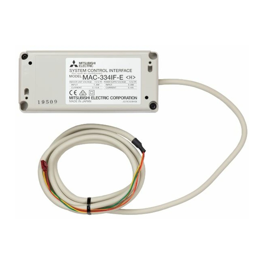
SYSTEM CONTROL Interface
MAC-334IF-E
Model
[FOR INSTALLER]
INSTALLATION MANUAL
[POUR L’INSTALLATEUR]
MANUEL D’INSTALLATION
English
Français
Related Manuals for Mitsubishi Electric MAC-334IF-E
Summary of Contents for Mitsubishi Electric MAC-334IF-E
-
Page 1
SYSTEM CONTROL Interface MAC-334IF-E Model [FOR INSTALLER] English INSTALLATION MANUAL [POUR L’INSTALLATEUR] Français MANUEL D’INSTALLATION… -
Page 2: Table Of Contents
Contents 1. Safety Instructions …………2 8. Connecting with M-NET system ……..6 2. Before Installation …………3 9. Connecting with MA remote controller ……7 3. Function and electric wiring of interface each part … 3 10. Remote Control …………..8 4.
-
Page 3: Before Installation
2. Before Installation How to Use the SYSTEM CONTROL Interface. Functions Connecting with M-NET system (Fig. 2-1) The room air conditioner can be managed centralized or individually by the system controller using M-NET communications control. Used as wired remote controller (Fig. 2-2) MA remote controller can be used as a wired remote controller.
-
Page 4: Dip Switch Details
4. Dip Switch Details Refer to Functions SW No. Functions OFF (Factory setting) section SW500-1 Output setting Switching output of heater ON/OFF (single operation) SW500-2 Turn on/off with power Not available Available SW500-3 Room temperature detector Indoor unit MA remote controller SW500-4 Output setting Switching output of ON/OFF, error/normal, heater ON/OFF, and humidifier ON/OFF…
-
Page 5: Connecting The System Control Interface To A Room Air Conditioner
6. Connecting the SYSTEM CONTROL Interface to a room air conditioner ➊ Connect the interface unit and the indoor control board of a room air conditioner using the connecting cable (5-core) that comes with the interface ➊ unit Thin part of the connecting cable Make sure to wire and shield the cable ➊…
-
Page 6: Connecting With M-Net System
8. Connecting with M-NET system ■ Connecting the SYSTEM CONTROL Interface to M-NET cable The room air conditioner can be managed centralized or individually by the system controller using M-NET communications control. Indoor unit B2 A2 B1 A1 System controller, Power supply unit TB520 TB521…
-
Page 7: Connecting With Ma Remote Controller
9. Connecting with MA remote controller ■ Connecting the SYSTEM CONTROL Interface to MA remote controller A room air conditioner can be operated with the wired remote control. MA remote controller cable Indoor unit SW500 Screw for ➐ mounting TB580 SW502 Mounting cord MA remote controller…
-
Page 8: Remote Control
10. Remote Control ■ Connecting the SYSTEM CONTROL Interface Signal cable You can turn room air conditioner on/off, prohibit/allow manual operations, or input of heating/cooling with the ON/OFF switch. ➊ Interface unit Switch1, Switch2 Indoor unit (Usable at DC 12 V, 0.5 to 2.0 mA) CN591 ➓…
-
Page 9: Setting Signal Output
11. Setting Signal Output ■ Connecting the SYSTEM CONTROL Interface Each relay can be turned ON/OFF by synchronizing with the room air conditioner’s ON/OFF, error/normal, Heater ON/Heater OFF, and Humidifier ON/Humidifier OFF. Screw ➊ Interface unit driver Indoor unit Relay 2 Relay 1, 2: Terminal (Coil rating of DC 12 V, 1.0 W or…
-
Page 10: Turn On/Off With Power
12. Turn on/off with power The room air conditioner turns on when power is supplied. When using for the first time, set to the operational status of your choice with the remote controller and leave the power off for 1 minute. * When not used for a long period of time, you should set to the operational status of your choice again with the remote controller.
-
Page 11
Table des matières 1. Consignes de sécurité …………22 8. Connexion au système M-NET ……..26 2. Avant l’installation …………. 23 9. Raccordement de la télécommande MA ……27 3. Fonction et câblage électrique de chaque pièce de l’interface … 23 10. -
Page 12: Avant L’installation
2. Avant l’installation Comment utiliser l’interface COMMANDE DE SYSTÈME. Fonctions Connexion au système M-NET (Fig. 2-1) Le climatiseur peut être géré de manière centralisée ou individuelle par le contrôleur du système à l’aide de la commande de communication M-NET. Utilisé en tant que télécommande par câble (Fig. 2.2) Vous pouvez utiliser la télécommande MA comme télécommande par câble.
-
Page 13: Détails Des Commutateurs Dip
4. Détails des commutateurs DIP Reportez-vous Fonctions N° SW Fonctions Arrêt (Réglage d’usine) Marche à la section SW500-1 Réglage de la sortie Commutation de la sortie du chauffage sur ON/OFF (opération unique) SW500-2 Activer/désactiver avec alimentation Non disponible Disponible SW500-3 Détecteur de la température Appareil intérieur Télécommande MA ambiante…
-
Page 14: Raccordement De L’interface De La Commande De Système Sur Un Climatiseur
6. Raccordement de l’interface de la COMMANDE DE SYSTÈME sur un climatiseur ➊ ➊ Raccordez l’interface et la carte de commande intérieure d’un climatiseur à l’aide d’un câble de raccordement (5 âmes) fourni avec l’interface Partie mince du câble de raccordement Assurez-vous de câbler et de blinder le ➊…
-
Page 15: Connexion Au Système M-Net
8. Connexion au système M-NET ■ Raccordement de l’interface de la COMMANDE DE SYSTÈME sur un câble M-NET Le climatiseur peut être géré de manière centralisée ou individuelle par le contrôleur du système à l’aide de la commande de communication M-NET. Appareil intérieur B2 A2 B1 A1 Contrôle du…
-
Page 16: Raccordement De La Télécommande Ma
9. Raccordement de la télécommande MA ■ Raccordement de l’interface de la COMMANDE DE SYSTÈME sur la télécommande Il est possible d’utiliser un climatiseur avec la télécommande par câble. Câble de la télécommande MA Appareil intérieur SW500 Vis de ➐ montage TB580 SW502…
-
Page 17: Télécommande
10. Télécommande ■ Connecting the SYSTEM CONTROL Interface Câble de signal Vous pouvez mettre le climatiseur ON/OFF tension ou interdire/autoriser le fonctionnement manuel ou l’entrée du chauffage/refroidissement à l’aide du commutateur ON/OFF. ➊ Interface Commutateur 1, Commutateur 2 Appareil intérieur (Utilisable sous 12 V CC, 0,5 à…
-
Page 18: Con Guration De La Sortie Du Signal
11. Configuration de la sortie du signal ■ Raccordement de l’interface de la COMMANDE DE SYSTÈME Chaque relais peut être positionné sur ON/OFF en synchronisant la mise ON/OFF du climatiseur, erreur/normal, chauffage ON/chauffage OFF et humidificateur ON/humidificateur OFF. ➊ Interface Tournevis Appareil intérieur Relai 2…
-
Page 19: Activer/Désactiver Avec Alimentation
12. Activer/désactiver avec alimentation Le climatiseur s’allume lorsqu’il est alimenté. Lors de la première utilisation, réglez l’état de votre choix à l’aide de la télécommande et laissez l’alimentation coupée pendant 1 minute. * Si le climatiseur n’est pas utilisé pendant une période prolongée, vous devez configurer à nouveau l’état de fonctionnement de votre choix à l’aide de la télécommande. ➊…
-
Page 20: Montage De L’interface De La Commande De Système
14. Montage de l’interface de la COMMANDE DE SYSTÈME Remarques ➊ ➊ doit être placée dans un endroit où le câble de raccordement (5 âmes) peut atteindre un appareil intérieur depuis l’interface être rallongé. ➊ ➋ sur un pilier ou un mur en utilisant au moins 2 vis ➊…
-
Page 21
Travellers Lane, Hat eld, Herts., AL10 8XB, England, U.K. Polish Branch Krakowska 50, PL-32-083 Balice, Poland MITSUBISHI ELECTRIC TURKEY ELEKTR K ÜRÜNLERI A. erifali Mah. Kale Sok. No:41 34775 Ümraniye, stanbul/Turkey MITSUBISHI ELECTRIC (RUSSIA) LLC 115114, Russia, Moscow, Letnikovskaya street 2, bld. 1, 5th… -
Page 23
This product is designed and intended for use in the residential, commercial and light-industrial environment. HEAD OFFICE: TOKYO BUILDING, 2-7-3, MARUNOUCHI, CHIYODA-KU, TOKYO 100-8310, JAPAN JG79Y451H01 Printed in Japan…
-
Contents
-
Table of Contents
-
Bookmarks
-
ENGLISH, page 2
-
РУССКИЙ, страница 153
-
FRANÇAIS, page 22
-
ESPAÑOL, página 42
-
DEUTSCH, seite 12
-
ITALIANO, pagina 52
-
DUTCH, pagina 32
-
PORTUGUÊS, página 72
-
SVENSKA, sida 92
-
POLSKI, strona 122
-
DANSK, side 82
-
SUOMI, sivu 112
-
NORSK, side 102
-
ΕΛΛΗΝΙΚΆ, σελίδα 62
-
TÜRKÇE, sayfa 142
-
БЪЛГАРСКИ, страница 132
-
ไทย, หน้า 183
Quick Links
SYSTEM CONTROL Interface
MAC-334IF-E
Model
[FOR INSTALLER]
INSTALLATION MANUAL
[FÜR INSTALLATEURE]
INSTALLATIONSHANDBUCH
[POUR L’INSTALLATEUR]
MANUEL D’INSTALLATION
[VOOR DE INSTALLATEUR]
INSTALLATIEHANDLEIDING
[PARA EL INSTALADOR]
MANUAL DE INSTALACIÓN
[PER L’INSTALLATORE]
MANUALE DI INSTALLAZIONE
[ΓΙΑ ΑΥΤΟΝ ΠΟΥ ΚΑΝΕΙ ΤΗΝ ΕΓΚΑΤΑΣΤΑΣΗ]
ΕΓΧΕΙΡΙΔΙΟ ΟΔΗΓΙΩΝ ΕΓΚΑΤΑΣΤΑΣΗΣ
[PARA O INSTALADOR]
MANUAL DE INSTALAÇÃO
[TIL INSTALLATØREN]
INSTALLATIONSMANUAL
[FÖR INSTALLATÖREN]
INSTALLATIONSMANUAL
[FOR MONTØREN]
INSTALLERINGSHÅNDBOK
[ASENTAJALLE]
ASENNUSOPAS
[DLA INSTALATORA]
INSTRUKCJA MONTAŻU
[ЗА ИНСТАЛАТОРА]
РЪКОВОДСТВО ЗА МОНТАЖ
[MONTÖR İÇİN]
MONTAJ ELKİTABI
[ДЛЯ УСТАНОВИТЕЛЯ]
РУКОВОДСТВО ПО УСТАНОВКЕ
[
]
[
]
[
]
English
Deutsch
Français
Nederlands
Español
Italiano
Ελληνικά
Português
Dansk
Svenska
Norsk
Suomi
Polski
Български
Türkçe
Русский
Chapters
Summary of Contents for Mitsubishi Electric MAC-334IF-E
Комбинированный интерфейс Mitsubishi Electric MAC-333IF-E для подключения к сигнальной линии M-NET VRF-систем CITY MULTY, а также для подключения внешних цепей управления, проводных пультов и контроля.
Отличительные особенности Mitsubishi Electric MAC-333IF-E:
- Подключение к внутреннему блоку
- Подключение к сигнальной линии М-NET
- Подключение МА-пульта и формирование групп
- Управление внешними сигналами
- Управление внешними сигналами
- Автоматическое включение кондиционера при включении электропитания
- Проверка состояния обмена данных
- Каждый конвертор Mitsubishi Electric MAC-333IF-E предназначен только для одного внутреннего блока
- Конвертор выполнен в собственном корпусе и подключается к плате внутреннего блока кондиционера Mitsubishi Electric
| Гарантия | 3 года |
| Страна производитель | Япония |
| Характеристики: | |
| Размеры ШxДxВ, мм | 2160х70х54 |
| Document’s Content and Additional Information | Share Manual |
|---|---|
|
Mitsubishi Electric MAC-334IF-E Installation manual
Pages Preview: Document Transcription:
See Details |
|
|
Mitsubishi Electric MAC-334IF-E Installation manual
Pages Preview: Document Transcription:
See Details |


Download Installation manual of Mitsubishi Electric MAC-334IF-E Recording Equipment for Free or View it Online on All-Guides.com.

1

2

3

4

5

6

7

8

9

10

11

12

13

14

15

16

17

18

19

20

21

22

23

[FOR INSTALLER]
INSTALLATION MANUAL
[POUR L’INSTALLATEUR]
MANUEL D’INSTALLATION
SYSTEM CONTROL Interface
Model
MAC-334IF-E
English
Français