
-
Contents
-
Table of Contents
-
Troubleshooting
-
Bookmarks
Quick Links
MDM300 I.S.
Advanced Dew-Point Hygrometer
User’s Manual
97213 Issue 5
October 2017
Related Manuals for Michell Instruments MDM300 I.S
Summary of Contents for Michell Instruments MDM300 I.S
-
Page 1
MDM300 I.S. Advanced Dew-Point Hygrometer User’s Manual 97213 Issue 5 October 2017… -
Page 2
Please fi ll out the form(s) below for each instrument that has been purchased. Use this information when contacting Michell Instruments for service purposes. Hygrometer Code Serial Number Invoice Date Location of Instrument Tag No Hygrometer Code Serial Number Invoice Date… -
Page 3
© 2017 Michell Instruments This document is the property of Michell Instruments Ltd. and may not be copied or otherwise reproduced, communicated in any way to third parties, nor stored in any Data Processing System without the express written authorization of Michell Instruments Ltd. -
Page 4: Table Of Contents
Safety …………………… 9 Unpacking the Instrument ………………. 9 MDM300 I.S. Accessories ……………… 10 Operational Requirements …………….. 12 2.4.1 Environmental Requirements – MDM300 I.S. Instrument …….. 12 2.4.2 Charger Electrical Requirements …………..12 Instrument Gas Connections …………….12 2.5.1 Gas Inlet /Outlet Fittings …………….13 Connect External Sensors ………………
-
Page 5
MDM300 I.S. User’s Manual Guide to Measurement and Sampling …………..33 3.6.1 Measuring at Atmospheric or System Pressure ……….34 3.6.2 Measurement Guide ………………35 3.6.3 Conditional Sensor Purge …………….37 Battery Management ………………37 3.7.1 Battery Troubleshooting …………….37 GOOD MEASUREMENT PRACTICE …………..38… -
Page 6
Dimensions — MDM300 I.S……………..49 Figure 36 Current Datalog File Display …………..51 Figure 37 MDM300 I.S. Status Register …………..51 Figure 38 MDM300 I.S. Status Register (Hex 28) …………51 Tables Table 1 Controls and Indicators …………….4 Table 2 Instrument Display Descriptions …………..6 Table 3 Adaptor Fittings ……………… -
Page 7: Safety
Michell Instruments’ worldwide offi ces contact information. Calibration The recommended calibration interval for the MDM300 I.S. is 12 months. The instrument should be returned to the manufacturer, Michell Instruments Ltd., or one of their accredited service agents for re-calibration.
-
Page 8: Abbreviations
MDM300 I.S. User’s Manual Abbreviations The following abbreviations are used in this manual: alternating current pressure unit (atmosphere) barg pressure unit (=100 kP or 0.987 atm) gauge bara bar absolute °C degrees Celsius °F degrees Fahrenheit Kelvin (absolute temperature) common…
-
Page 9: Introduction
The MDM300 I.S. is fitted with an internally mounted ceramic sensor, which is enhanced for a quicker response to dew points as dry as -75°Cdp (-103°Fdp). The MDM300 I.S. can also be used to read the dew-point signal from a Michell Instruments’ Easidew I.S. transmitter. To do this, the MDM300 I.S. Remote Sensor Interface is used to connect to the Easidew I.S.
-
Page 10: Figure 1 Mdm300 I.s. Advanced Dew-Point Hygrometer
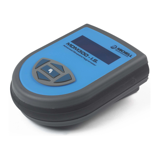
Two versions of the instrument are available, an MDM300 (standard) version and an MDM300 I.S. (intrinsically safe) version. This manual covers the MDM300 I.S. version only. For information about the MDM300 contact your local Michell Instruments’ representative (contact information at www.michell.com). MDM300 I.S. Advanced Dew-Point Hygrometer…
-
Page 11: Controls And Indicators
MDM300 I.S. User’s Manual INTRODUCTION Controls and Indicators The controls and indicators associated with the MDM300 I.S. instrument are located on the front panel of the instrument. Connections to the MDM300 I.S. dew-point hygrometer, comprising the gas ports, battery charger input connector and input connector for the external sensor are all made to the top panel.
-
Page 12: Table 1 Controls And Indicators
MDM300 I.S. User’s Manual INTRODUCTION Item Panel Description Function keys. Refer to Section 1.2 for the details of these Front keys. Instrument display, partitioned to show 3 main panels: The primary display shows internal sensor parameters. The secondary display indicates the external sensor Front parameter.
-
Page 13: Function Keys
MDM300 I.S. User’s Manual INTRODUCTION Function Keys The function keys, located on the front panel, are used to select operations from the menus and to select and enter parameter variables within those menu levels. The function key described is shaded darker and the operation of the keys is as follows: 1.2.1…
-
Page 14: Instrument Display
MDM300 I.S. User’s Manual INTRODUCTION Instrument Display The graphics display and the associated function keypad ( Figure 2), form the operator interface of the equipment. Figure 3 shows all the elements of a typical display page after the instrument’s initialization period has completed.
-
Page 15: Display Units
MDM300 I.S. User’s Manual INTRODUCTION 1.3.1 Display Units The instrument can display the measured reading in the following units: Absolute Humidity • lb/MMscf • • Moisture Content • ppmV NG • ppmV • ppmW (AIR, USER, H , SF , CO…
-
Page 16: Status Display Indications
MDM300 I.S. User’s Manual INTRODUCTION 1.3.2 Status Display Indications ‘ Initializing Internal Sensor’ This is displayed immediately after the instrument has been powered up, and indicates that the sensor is being heated up to accelerate equilibrium with the moisture in the sample gas.
-
Page 17: Installation
It is essential that the installation of the electrical and gas supplies to this instrument be undertaken by qualifi ed personnel. Unpacking the Instrument The MDM300 I.S. instrument is packed into a standard box and the method of unpacking is shown below: Packing Method Figure 4 Open the box (1) and unpack carefully.
-
Page 18: Mdm300 I.s. Accessories
INSTALLATION MDM300 I.S. Accessories The accessories for the MDM300 I.S. are shown in Figure 6 . Items 1 to 7 are supplied as standard and item 8 is optional. Please check that all the standard components are present after unpacking. Report any shortages immediately.
-
Page 19: Figure 6 Accessories
MDM300 I.S. User’s Manual INSTALLATION MDM300 & MDM300 I.S. Quick Start Guide Connect the MDM to the sample gas stream Determine the approximate Typical MDM300 Sampling Arrangement dew point by using the ‘initial check’ procedure on the reverse SAMPLE FLOW…
-
Page 20: Operational Requirements
Figure 5 . The MDM300 I.S. is supplied with a large bore orifice fitting installed into the Gas In and Gas Out ports. These fittings have an 1/8” NPT female thread to allow the user to connect other components of their choice.
-
Page 21: Gas Inlet /Outlet Fittings
Michell Instruments, on request. NOTE: The bonded seals used for the MDM300 I.S. are Dowty part number 400-228-4490-74 (from Michell Instruments, part number MDM300-DS).
-
Page 22: Connect External Sensors
The MDM300 I.S. Remote Sensor Interface is a passive device. The combined terminal parameters of the MDM300 I.S. and of the barrier used with the Easidew I.S. system must not exceed the input terminal parameters of the Easidew I.S. as specified in the System Drawing (System Certificate No.
-
Page 23: Set Up External Sensor Interface
2.6.2 Entering User Pressure The MDM300 I.S. can be programmed with a pressure to be used in the calculation of atmospheric equivalent or pressure dew point, moisture content or absolute humidity. NOTE: Care should be taken to ensure that the entered pressure is correct as it may have a considerable effect on the measurement.
-
Page 24: Battery Charging
Figure 12 Battery Charger Connection Connect an AC power supply, 100 to 240 V AC, 50/60 Hz, to the battery charger unit. NOTE: The MDM300 I.S. instrument does not need to be switched on in order to charge the battery.
-
Page 25
If the battery has been damaged then the charger will not begin the fast-charge stage. Please contact Michell Instruments’ service department for advice. Once the charger has finished the fast-charge stage it can be safely disconnected. Switch off the AC power supply, remove the charger unit and close the instrument’s charge connector protection cover. -
Page 26: Operation
Preparation for Operation The MDM300 I.S. has a user-friendly system of operation. Before operation it is recommended that the user becomes familiar with Section 1 of this manual in which the equipment controls and indicators, and the elements of the display are described.
-
Page 27: Instrument Start-Up
MDM300 I.S. User’s Manual OPERATION Instrument Start-Up At switch on, the instrument goes through an initialization process of between 4 and 7 minutes, MDM300 I.S. depending sensor sample System Initializing characteristics. During this time the internal sensor is heated to a maximum of +60°C (+140°F). The heating…
-
Page 28: Overall Menu Structure And Operation
MDM300 I.S. User’s Manual OPERATION Overall Menu Structure and Operation 3.3.1 SET-UP Menu All instrument settings are made from the SET-UP Menu which is accessible from the Main Display by pressing the key. Enter On the first occasion after switch-on the Passcode Entry page will be displayed. Enter…
-
Page 29: Figure 14 Menu Structure
MDM300 I.S. User’s Manual OPERATION Scroll Unit Files Page to view Chart Page Main Display (Primary, (only if internal sensor LOGGING? Secondary and Status Windows) available) Logs Page PASSCODE FOR SETUP (on start-up only) =7316 Scroll to Adjust Digit Chart Reset Page…
-
Page 30: Set-Up Menu Parameters
MDM300 I.S. User’s Manual OPERATION SET-UP Menu Parameters Follow the instructions in Section 3.3.1 to select the required parameters. 3.4.1 SETTINGS PRIMARY DP AT ATMOS SETTINGS DP/TEMP UNIT °C PRESSURE UNIT Psig GAS TYPE MOL WEIGHT CHART INTERVAL Figure 15 SETTINGS Page…
-
Page 31: Logging
MDM300 I.S. User’s Manual OPERATION 3.4.2 LOGGING Logging can be set up either from the SETTINGS Menu or from the Chart Page (see Section 3.4.8). Both methods of entry lead to the same LOGGING SET-UP menu as shown below: >…
-
Page 32: Bluetooth
3.4.3 BLUETOOTH Bluetooth mode is used, in conjunction with a dedicated MDM300 I.S. application software package, for the purpose of uploading datalog files to a PC using a wireless connection. Within the PC the dedicated Michell application software package is used to upload the files to the PC’s desktop, from where they can be loaded into other programs, e.g.
-
Page 33: 3.4.3.1 Bluetooth Pairing Procedure
MDM300. Double click the instrument icon and enter the instrument’s pairing passcode ( ) for all MDM300 I.S. instruments. NOTE: Each digit 7316 will be shown only briefly as it is entered and then hidden. When all digits have been entered click…
-
Page 34: External (Sensor Interface)
MDM300 I.S. User’s Manual OPERATION 3.4.4 EXTERNAL (Sensor Interface) The MDM300 I.S. is designed to be connected ONLY to a Michell Instruments’ remotely mounted Easidew I.S. or Easidew PRO I.S. transmitter. Connection to any other type of sensor could impair safety.
-
Page 35: Clock
MDM300 I.S. User’s Manual OPERATION 3.4.5 CLOCK YEAR CLOCK MONTH HOUR Figure 20 CLOCK Page Parameter Description Current year YEAR Available Input: Range: 00 to 99 Current month MONTH Available Input: Range: 01 to 12 Current day Available Input: Range: 01 to 31…
-
Page 36: Hmi
MDM300 I.S. User’s Manual OPERATION 3.4.6 CONTRAST BRIGHTNESS KEY TONE BL TIMEOUT LANGUAGE PRIMARY DISP INTERN Figure 21 HMI Page Parameter Description Sets the contrast on the screen. CONTRAST Available Input: Range: in 5% increments 0 to 100% Sets the brightness of the screen.
-
Page 37: Info
MDM300 I.S. User’s Manual OPERATION 3.4.7 INFO MDM300 I.S. Portable Hygrometer Firmware 36176 Ver 0.01 Sensor serial number E050-035 Sensor next cal due 03/09/12 Sensor hours used 20 hr www.michell.com Figure 22 INFO Page This page contains system information and no changes can be made.
-
Page 38: Log Files Page
Figure 24 LOG FILES Page The content of the datalog files cannot be examined but, by enabling the instrument’s Bluetooth mode, (see Section 3.4.3), the MDM300 I.S. application software may be used to upload the datalog files to a PC.
-
Page 39: 3.4.11 Calibration
MDM300 I.S. User’s Manual OPERATION The display shows: Indicates a log number for each set of log points Value of primary display parameter Value of secondary display parameter Status column which reports the status of the instrument at each log point in hexadecimal code.
-
Page 40: Default Parameters
Current UK time & date CONTRAST BRIGHTNESS Section 3.4.6, Figure 21 KEYTONE BL TIME-OUT LANGUAGE PRIMARY DISP INTERN CALIBRATION & INFO Section 3.4.11 & Section 6 Default values not applicable Table 10 MDM300 I.S. Default Parameters 97213 Issue 5, October 2017…
-
Page 41: Guide To Measurement And Sampling
MDM300 I.S. User’s Manual OPERATION Guide to Measurement and Sampling Operating the MDM300 I.S. is very straightforward, but sampling conditions can vary greatly from one application to another. To get the best possible response speed, the appropriate procedure should be followed.
-
Page 42: Measuring At Atmospheric Or System Pressure
MDM300 I.S. User’s Manual OPERATION It is highly recommended that a fi lter is installed upstream of the MDM300. Refer to the Sample Conditioning section of the Sampling Hints found in Section 4.1. 3.6.1 Measuring at Atmospheric or System Pressure…
-
Page 43: Measurement Guide
Table 11 MDM300 I.S. Measurement Procedures Standard Purge (Atmospheric Measurement) Connect the MDM300 I.S. to the sample gas stream. Adjust the flow rate, using the inlet flow control valve, to between 0.2 & 0.5 Nl/min (0.5 & 1 scfh). The outlet flow control valve should be fully open.
-
Page 44
OPERATION Standard Purge (Pressure Measurement) Connect the MDM300 I.S. to the sample gas stream. Adjust the flow rate, using the outlet flow control valve, to between 0.2 & 0.5 Nl/min (0.5 & 1 scfh). The inlet flow control valve should be fully open. -
Page 45: Conditional Sensor Purge
15 seconds or the battery may be damaged. NOTE: Michell Instruments will replace the older FW 7219 charger with the new Cell Con model free of charge. The Cell Con will re-charge batteries which have completely discharged.
-
Page 46: Good Measurement Practice
GOOD MEASUREMENT PRACTICE GOOD MEASUREMENT PRACTICE The MDM300 I.S. is designed to operate in a flowing gas stream with flow rates between 0.2 and 0.5 Nl/min (0.5 and 1 scfh). Flow regulation is provided with the MDM300 I.S. instrument between 2.5 and 10 barg. Outside of this, the sample flow must be regulated outside the unit.
-
Page 47: Sampling Hints
MDM300 I.S. User’s Manual GOOD MEASUREMENT PRACTICE Sampling Hints Measurement of moisture content is a complex subject, but does not need to be difficult. This section aims to explain the common mistakes made in measurement situations, the causes of the problem, and how to avoid them. Mistakes and bad practices can cause the measurement to vary from the expectation;…
-
Page 48
MDM300 I.S. User’s Manual GOOD MEASUREMENT PRACTICE Sample Tubing Length The sample point should always be as close to the critical measurement point as possible, in order to obtain a truly representative measurement. The length of the sample line to the sensor or instrument should be as short as possible. Interconnection points and valves trap moisture, so using the simplest sampling arrangement possible will reduce the time it takes for the sample system to dry out when purged with dry gas. -
Page 49
Before disconnecting the MDM300 I.S. from the gas line it is essential to vent the system to atmospheric pressure, otherwise severe injury could result. -
Page 50: Application Software
MDM-300-7392 Once the software has been installed and run, the MDM300 I.S. can be linked to the PC by activating the Bluetooth on the MDM300 I.S. and then connecting with the application software (see Section 3.4.3 for details).
-
Page 51: Calibration
If these facilities do not exist it is recommended that the instrument be returned to the manufacturer, Michell Instruments Ltd., or one of the approved agents. A calibration certificate bearing a seven point calibration is issued with each instrument.
-
Page 52: Calibration Method
Ensure that all sample tubing and connectors are made from stainless steel and are of suitable quality. Connect the MDM300 I.S. to a dew-point generator and establish a gas flow through the instrument. Apply a dew point of -100°C and allow the instrument’s reading to stabilize for a minimum of 96 hours (including dry down).
-
Page 53: Calibration Correction Method
-70.0 -60.0 -60.0 Figure 31 Calibration Menu Page The MDM300 I.S. Calibration look-up table is divided into three columns. The values in the first column represent the thirteen nominal calibration points, POINT spread at 10°C intervals over the instruments operating range of -100 to +20°C (-148 to +68°F…
-
Page 54: Shipping
Create a packing list detailing all equipment contained in the box, place it inside the box and seal the box. Before disconnecting the MDM300 I.S. from the gas line it is essential to vent the system to atmospheric pressure, otherwise severe injury could result.
-
Page 55
MDM300 I.S. User’s Manual APPENDIX A Appendix A Technical Specifi cations Michell Instruments… -
Page 56: Appendix A Technical Specifi Cations
MDM300 I.S. User’s Manual APPENDIX A Appendix A Technical Specifi cations Performance Measurement Technology Michell Ceramic Sensor ±1°C from -60 to +20°Cdp (-76 to +68°Fdp) Accuracy ±2°C from -100 to -60°Cdp (-148 to -76°Fdp) ±0.2°C (0.3°F) temperature For Spot Checks -70 to +20°Cdp (-95 to +68°Fdp)
-
Page 57: Dimensions
Certifi cation Codes TC TR Ex 0Ex ia IIC T4 Ga Class I, Division 1, Groups A B C D, T4 Class I, Division 1, Groups A B C D, T4 Dimensions Figure 35 Dimensions — MDM300 I.S. Michell Instruments…
-
Page 58
MDM300 I.S. User’s Manual APPENDIX B Appendix B Datalog Status Display 97213 Issue 5, October 2017… -
Page 59: Appendix B Datalog Status Display
Figure 36 . Bit 1 is the least significant bit. The four most significant bits 13 to 16 are for Michell Instruments’ service use and so the first character in any MDM300 I.S. ST display will always read 0.
-
Page 60: Table 13 Status Register Flags
MDM300 I.S. User’s Manual APPENDIX B Table 13 shows the status flags associated with each bit of the status register. If a status flag is set high then the associated condition exists. If it is set low, then that condition does not exist.
-
Page 61
MDM300 I.S. User’s Manual APPENDIX C Appendix C Hazardous Area Certifi cation Michell Instruments… -
Page 62: Appendix C Hazardous Area Certifi Cation
APPENDIX C Appendix C Hazardous Area Certifi cation The MDM300 I.S is certified compliant to the ATEX Directive (2014/34/EU) and IECEx for use within Zone 0 Hazardous Area, and has been assessed so by Baseefa Ltd (Notified Body 1180). The MDM300 I.S is certified compliant to North American Standards (USA and Canada) for use within Class I, Division 1, Groups A, B, C &…
-
Page 63: Special Conditions Of Use
None Maintenance and Installation The MDM300 I.S. must only be installed by suitably qualified personnel and in accordance with the instructions provided and the terms of the applicable product certificates. Maintenance and servicing of the product must only be carried out by suitably trained personnel or returned to an approved Michell Instruments’…
-
Page 64
MDM300 I.S. User’s Manual APPENDIX D Appendix D FCC Declaration 97213 Issue 5, October 2017… -
Page 65: Appendix Dfcc Declaration
APPENDIX D Appendix D FCC Declaration MDM300 I.S. Advanced Dewpoint Hygrometer. This Device complies with FCC Rules Part 15 Subpart B Unintentional Radiators Class B digital devices. Operation is subject to the following conditions: 1) This device may not cause harmful interference 2) This device must accept any interference received, including interference that may cause undesired operation.
-
Page 66
MDM300 I.S. User’s Manual APPENDIX E Appendix E Quality, Recycling & Warranty Information 97213 Issue 5, October 2017… -
Page 67: Appendix E Quality, Recycling & Warranty Information
MDM300 I.S. User’s Manual APPENDIX E Appendix E Quality, Recycling & Warranty Information Michell Instruments is dedicated to complying to all relevant legislation and directives. Full information can be found on our website at: www.michell.com/compliance This page contains information on the following directives: •…
-
Page 68
APPENDIX F MDM300 I.S. User’s Manual Appendix F Return Document & Decontamination Declaration 97213 Issue 5, October 2017… -
Page 69: Appendix F Return Document & Decontamination Declaration
Has the equipment been cleaned and decontaminated? NOT NECESSARY Michell Instruments will not accept instruments that have been exposed to toxins, radio-activity or bio-hazardous Work will not be carried out on any unit that does not have a completed decontamination declaration.
-
Page 70
MDM300 I.S. User’s Manual NOTES: 97213 Issue 5, October 2017… -
Page 72
http://www.michell.com…
-
Contents
-
Table of Contents
-
Troubleshooting
-
Bookmarks
Quick Links
MDM300 I.S.
Advanced Dew-Point Hygrometer
User Manual
97213 Issue 6.2
August 2021
Related Manuals for Michell Instruments MDM300 I.S.
Summary of Contents for Michell Instruments MDM300 I.S.
-
Page 1
MDM300 I.S. Advanced Dew-Point Hygrometer User Manual 97213 Issue 6.2 August 2021… -
Page 2
Please fill out the form(s) below for each instrument that has been purchased. Use this information when contacting Michell Instruments for service purposes. Product Name Order Code Serial Number Invoice Date Installation Location Tag Number Product Name Order Code Serial Number… -
Page 3
© 2021 Michell Instruments This document is the property of Michell Instruments Ltd and may not be copied or otherwise reproduced, communicated in any way to third parties, nor stored in any Data Processing System without the express written authorization of Michell Instruments Ltd. -
Page 4: Table Of Contents
MDM300 I.S. User Manual Contents Safety ……………………..vii Electrical Safety ………………….vii Pressure Safety ………………….vii Toxic Materials ………………….vii Repair and Maintenance ………………..vii Calibration ……………………vii Safety Conformity …………………..vii Abbreviations ……………………viii Warnings …………………….. viii INTRODUCTION ………………..1 Controls and Indicators ………………3 Function Keys ………………… 5 1.2.1 Enter Key …………………
-
Page 5
Input Terminal Parameters …………51 Special Conditions of Use …………. 52 Maintenance and Installation …………52 Appendix D FCC Declaration ………………54 Appendix E Quality, Recycling & Warranty Information ……….. 56 Appendix F Return Document & Decontamination Declaration ……..58 Michell Instruments… -
Page 6
MDM300 I.S. User Manual Figures Figure 1 MDM300 I.S. Advanced Dew-Point Hygrometer ……….2 Figure 2 User Connections, Controls and Indicators …………3 Figure 3 Instrument Display ………………6 Figure 4 Packing Method ………………9 Figure 5 Gas Port Adaptors ………………10 Figure 6 Accessories ………………..11 Figure 7 Bonded Seal Fitting ………………13 Figure 8… -
Page 7: Safety
Michell Instruments’ worldwide offices contact information. Calibration The recommended calibration interval for the MDM300 I.S. is 12 months. The instrument should be returned to the manufacturer, Michell Instruments Ltd, or one of their accredited service agents for re-calibration. Safety Conformity This product meets the essential protection requirements of the relevant UK and EU directives.
-
Page 8: Abbreviations
MDM300 I.S. User Manual Abbreviations The following abbreviations are used in this manual: alternating current pressure unit (atmosphere) barg pressure unit (=100 kP or 0.987 atm) gauge bara bar absolute °C degrees Celsius °F degrees Fahrenheit Kelvin (absolute temperature) common direct current foot (feet) Hertz…
-
Page 9: Introduction
PC based, MDM300 I.S. Software Application Package which provides the facility for handling the logged data files and uploading and downloading instrument parameters. A user-friendly operator interface provides easy access to all levels of the instrument’s functionality. An easy-to-follow calibration routine is built into the instrument’s software. Michell Instruments…
-
Page 10: Figure 1 Mdm300 I.s. Advanced Dew-Point Hygrometer
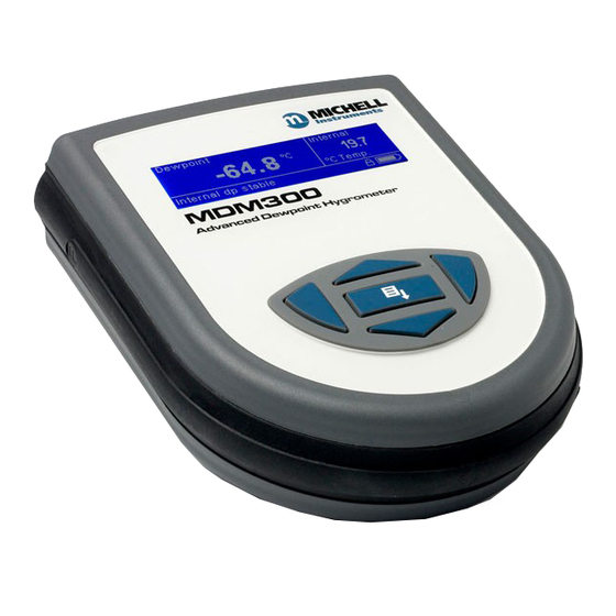
Two versions of the instrument are available, an MDM300 (standard) version and an MDM300 I.S. (intrinsically safe) version. This manual covers the MDM300 I.S. version only. For information about the MDM300 contact your local Michell Instruments’ representative (contact information at www.michell.com). Figure 1 MDM300 I.S.
-
Page 11: Controls And Indicators
Figure 2 shows the layout of these controls and Table 1 describes their respective operational functions. — I.S. Fig 2.1_V6 Figure 2 User Connections, Controls and Indicators Michell Instruments…
-
Page 12: Table 1 Controls And Indicators
MDM300 I.S. User Manual INTRODUCTION Item Panel Description Function keys. Refer to Section 1.2 for the details of these Front keys. Instrument display, partitioned to show 3 main panels: The primary display shows internal sensor parameters. The secondary display indicates the external sensor Front parameter.
-
Page 13: Function Keys
As the insertion point is shifted to the left, the entry at the former position is deleted. Within any menu or sub-menu level, pressing this ƒ key escapes to the previous menu above the current level. Michell Instruments…
-
Page 14: Instrument Display
MDM300 I.S. User Manual INTRODUCTION Instrument Display The graphics display and the associated function keypad ( Figure 2), form the operator interface of the equipment. Figure 3 shows all the elements of a typical display page after the instrument’s initialization period has completed. Table 2 details the elements of the display: Dewpoint Internal…
-
Page 15: Display Units
, CO or N Dew Point • °C • °F • Relative Humidity (%) Mixing Ratio • g/kg (AIR, USER, H , SF , CO or N To toggle between displayed units, press either the or key. Michell Instruments…
-
Page 16: Status Display Indications
MDM300 I.S. User Manual INTRODUCTION 1.3.2 Status Display Indications ‘ Initializing Internal Sensor’ Initializing Internal Sensor’ This is displayed immediately after the instrument has been powered up, and indicates that the sensor is being heated up to accelerate equilibrium with the moisture in the sample gas.
-
Page 17: Installation
Save all the packing materials for the purpose of returning the instrument for re-calibration or any warranty claims. If the optional carry bag has been ordered it will be located underneath the foam insert, in a cardboard box. Michell Instruments…
-
Page 18: Mdm300 I.s. Accessories
MDM300 I.S. User Manual INSTALLATION MDM300 I.S. Accessories The accessories for the MDM300 I.S. are shown in Figure 6 . Items 1 to 5 are supplied as standard and item 6 is optional. Please check that all the standard components are present after unpacking.
-
Page 19: Figure 6 Accessories
HIGH PRESSURE! High pressure gases are potentially hazardous. Energy stored in these gases can be released suddenly and with extreme force. High pressure systems should be assembled and operated only by people who have been trained in proper safety practices. 97244 Issue 2.2, September 2013 Figure 6 Accessories Michell Instruments…
-
Page 20: Operational Requirements
MDM300 I.S. User Manual INSTALLATION Operational Requirements Operational requirements are as follows: Sample gas flow rate: 0.2 to 0.5 Nl/min (0.5 to 1 scfh) Operating pressure: 0 to 350 barg (0 to 5076 psig) 2.4.1 Environmental Requirements – MDM300 I.S. Instrument Operating temperature range: -20 to +50°C (-4 to +122°F) Humidity:…
-
Page 21: Gas Inlet /Outlet Fittings
Michell Instruments, on request. NOTE: The bonded seals used for the MDM300 I.S. are Dowty part number 400-228-4490-74 (from Michell Instruments, part number MDM300-DS). Michell Instruments…
-
Page 22: Battery Charging
MDM300 I.S. User Manual INSTALLATION Battery Charging WARNING: The battery charger must NOT be connected within the hazardous area. The battery charger socket cover MUST be closed when the product is in use within a hazardous area. The MDM300 I.S. is powered from an internally mounted, rechargeable Nickel Metal Hydride (NiMH) battery.
-
Page 23
If the battery has been damaged then the charger will not begin the fast-charge stage. Please contact Michell Instruments’ service department for advice. Once the charger has finished the fast-charge stage it can be safely disconnected. Switch off the AC power supply, remove the charger unit and close the instrument’s charge connector protection cover. -
Page 24: Operation
MDM300 I.S. User Manual OPERATION OPERATION High pressure gases are potentially dangerous. POSSIBLE INJURY! The tubing, valves and other apparatus attached to this instrument must be adequate for the maximum pressure which will be applied, otherwise physical injury to the operator or bystander is possible. Preparation for Operation The MDM300 I.S.
-
Page 25: Instrument Start-Up
Measurement in progress Measurement in progress message is displayed. After this, depending on the sample conditions, the instrument may continue to respond to the final dew-point for a number of minutes. This is further explained in Section 3.6. Michell Instruments…
-
Page 26: Overall Menu Structure And Operation
MDM300 I.S. User Manual OPERATION Overall Menu Structure and Operation 3.3.1 SET-UP Menu All instrument settings are made from the SET-UP Menu which is accessible from the Main Display by pressing the Enter Enter key. On the first occasion after switch-on the Passcode Entry page will be displayed. Enter the passcode 7316 7316…
-
Page 27: Figure 11 Menu Structure
EXTERNAL ZERO EXTERNAL SPAN PASSCODE USER PRESSURE YEAR MONTH HOUR CONTRAST BRIGHTNESS KEY TONE BL TIMEOUT LANGUAGE PRIMARY DISP POINT MDM300 INFO PAGE LEGEND Enter Key Up/Down Keys Left Right Keys Figure 11 Menu Structure * No longer available Michell Instruments…
-
Page 28: Set-Up Menu Parameters
MDM300 I.S. User Manual OPERATION SET-UP Menu Parameters Follow the instructions in Section 3.3.1 to select the required parameters. 3.4.1 SETTINGS PRIMARY DP AT ATMOS SETTINGS DP/TEMP UNIT °C PRESSURE UNIT Psig GAS TYPE MOL WEIGHT CHART INTERVAL Figure 12 SETTINGS Page Parameter Description Indicates if the primary display sensor is at atmospheric or system…
-
Page 29: Logging
The size of any one log file is limited to 60kb. If the unit is left logging, and the file size exceeds 60kb, then the log file will finish automatically. To ensure that the log file you initiate collects all the data from your test, an Michell Instruments…
-
Page 30: Bluetooth
MDM300 I.S. User Manual OPERATION appropriate sample time should be chosen. The table below can be used as a rough guide: Sample time (sec) Logging duration 3 hours 6 hours 18 hours 36 hours 60 hours 120 hours 240 hours 360 hours 3.4.3 BLUETOOTH…
-
Page 31: 3.4.3.1 Bluetooth Pairing Procedure
. NOTE: The name of With the serial link established, click Configure Configure the COM port allocated, i.e. COM7, will need to be entered when starting the Michell application software. (7) (3) (1) (6) Figure 15 Typical Bluetooth Pairing Sequence Michell Instruments…
-
Page 32: Clock
MDM300 I.S. User Manual OPERATION 3.4.4 CLOCK YEAR CLOCK MONTH HOUR Figure 16 CLOCK Page YEAR CLOCK MONTH HOUR Parameter Description Current year YEAR YEAR Available Input: Range: 00 to 99 YEAR CLOCK MONTH Current month MONTH MONTH HOUR Available Input: Range: 01 to 12 Current day Available Input: Range: 01 to 31 Current hour…
-
Page 33: Info
Figure 18 INFO Page This page contains system information and no changes can be made. Information available: • Firmware number and version • Sensor serial number • Date of sensor calibration next due • Hours that the sensor has been used Michell Instruments…
-
Page 34: Chart Page
MDM300 I.S. User Manual OPERATION 3.4.7 CHART Page At any time while the Main Display is indicating internal sensor parameters, a graphical display of the output can be obtained by pressing the key from the Main Display. The chart can be reset at any time by pressing the Enter Enter key.
-
Page 35: Logs Page
Logging interval • Current date in YYMMDD format • T# T# Current time in HHMMSS format NOTE: The chart and datalogging are independent functions; therefore the parameter displayed on the chart may not necessarily reflect what is being logged. Michell Instruments…
-
Page 36: 3.4.10 Calibration
MDM300 I.S. User Manual OPERATION 3.4.10 CALIBRATION Input passcode for setup menu WARNING: These procedures require the use of specialized test equipment and calibration adjustments should only be 0 0 0 carried out by qualified personnel. POINT MDM300 CALIBRATION -100 -100.0 -100.0 -90.0…
-
Page 37: Default Parameters
Current UK time & date CONTRAST BRIGHTNESS Section 3.4.5, Figure 17 KEYTONE BL TIME-OUT LANGUAGE PRIMARY DISP INTERN CALIBRATION & INFO CALIBRATION & INFO Section 3.4.10 & Section 6 Default values not applicable Table 9 MDM300 I.S. Default Parameters Michell Instruments…
-
Page 38: Guide To Measurement And Sampling
For the most basic measurement it is recommended to have a flow meter (0 to 1 l/min), and at least one metering valve. A number of sampling kits are available from Michell Instruments: • The Easi-fit sample kit is a low cost sampling system consisting of 2 metering valves and a flow meter which is suitable for many applications.
-
Page 39: Measuring At Atmospheric Or System Pressure
The metering valve on the inlet should be used to control the sample flow. To measure at system pressure the metering valve on the instrument inlet should be fully open. The metering valve on the outlet should be used to control the sample flow. Michell Instruments…
-
Page 40: Measurement Guide
MDM300 I.S. User Manual OPERATION 3.6.2 Measurement Guide Follow procedure A and note the result. Turn the instrument off. If you wish to measure at sample pressure then use the Michell Humidity Calculator (http://www.michell.com/uk/downloads/humidity_calculator. msi) to convert this result back to the equivalent at your sample pressure. Using this converted result, and the table below, find the appropriate procedure to measure your sample.
-
Page 41
Once ‘ Measurement in progress’ Measurement in progress’ has disappeared, the instrument is close to the final dew point. Depending on the conditions, it may continue to respond for a number of minutes before tracking the measured dew point. Michell Instruments… -
Page 42: Conditional Sensor Purge
15 seconds or the battery may be damaged. NOTE: Michell Instruments will replace the older FW 7219 charger with the new Cell Con model free of charge. The Cell Con will re-charge batteries which have completely discharged.
-
Page 43: Good Measurement Practice
The table below offers an approximate guide to the times taken for the instrument to stabilize at a given dew point (from a starting point of 10°Cdp ambient): Target Dew Point (°C) T100 response time from ambient (hours) -100 Michell Instruments…
-
Page 44: Sampling Hints
MDM300 I.S. User Manual GOOD MEASUREMENT PRACTICE Sampling Hints Ensuring reliable and accurate moisture measurements requires the correct sampling techniques, and a basic understanding of how water vapor behaves. This section aims to explain the common mistakes and how to avoid them. Sampling Materials –…
-
Page 45
Theoretically flow rate has no direct effect on the measured moisture content, but in practice it can have unanticipated effects on response speed and accuracy. An inadequate flow rate may: Michell Instruments… -
Page 46
MDM300 I.S. User Manual GOOD MEASUREMENT PRACTICE • Accentuate adsorption and desorption effects on the gas passing through the sampling system. • Allow pockets of wet gas to remain undisturbed in a complex sampling system, which will then gradually be released into the sample flow. •… -
Page 47: Application Software
These can be downloaded to a specific location by right clicking, and selecting ‘ download download ’. A context sensitive help file provides further details on the use of the application software. Figure 26 Typical Application Software Screen Michell Instruments…
-
Page 48: Calibration
If these facilities do not exist it is recommended that the instrument be returned to the manufacturer, Michell Instruments Ltd., or one of the approved agents. A calibration certificate bearing a seven point calibration is issued with each instrument.
-
Page 49: Calibration Method
A set of results similar to that shown below could be generated over the calibration range of the instrument. Stabilize Stabilize DP REF MDM300 I.S. DP REF MDM300 I.S. Time Time °C Rdg °C °C Rdg °C (Hours) (Hours) -100 -99.8 -30.1 -79.7 -19.9 -59.8 -49.8 -39.9 Table 11 Example Of Calibration Run Readings Michell Instruments…
-
Page 50: Calibration Correction Method
MDM300 I.S. User Manual CALIBRATION Calibration Correction Method NOTE: Any logging procedure currently in operation must be cancelled before the calibration procedures can be entered. CALIBRATION CALIBRATION To enter the CALIBRATION Menu page, highlight from the SET-UP Menu by using the or keys and press the Enter Enter key.
-
Page 51: Shipping
Create a packing list detailing all equipment contained in the box, place it inside the box and seal the box. Before disconnecting the MDM300 I.S. from the gas line it is essential to vent the system to atmospheric pressure, otherwise severe injury could result. Figure 29 Instrument Packing Details Michell Instruments…
-
Page 52
MDM300 I.S. User Manual APPENDIX A Appendix A Technical Specifications 97213 Issue 6.2, August 2021… -
Page 53: Appendix A Technical Specifications
1/8” NPT female (other options available) Gas Wetted Materials AISI 316L stainless steel, PTFE Seal, Borosilicate glass, ceramic Outline Dimensions 218 x 170 x 90mm (8.6 x 6.7 x 3.5ft) (d x w x h) Weight 1.5kg (3.3lbs) Michell Instruments…
-
Page 54: Dimensions
MDM300 I.S. User Manual APPENDIX A Capacity: 8Mb Data Logging Log interval: 5…60 sec Maximum log file size: 60kb Communications (Wireless) Bluetooth range up to 5m (16ft) (Version 2.0) Languages English, German, Spanish, French, Italian, Portuguese Hazardous Area Certification Certification Codes See Appendix C * The end user has a responsibility to ensure that when installed in the Hazardous Area, the system is compliant with relevant local and international installation Standards for the use of equipment in explosive atmospheres.
-
Page 55
MDM300 I.S. User Manual APPENDIX B Appendix B Datalog Status Display Michell Instruments… -
Page 56: Appendix B Datalog Status Display
Figure 36 . Bit 1 is the least significant bit. The four most significant bits 13…16 are for Michell Instruments’ service use and so the first character in any MDM300 I.S. ST display will always read 0.
-
Page 57: Table 14 Status Register Flags
External sensor error’ and bit 6 set ‘ Measurement in progress’ Measurement in progress’ Therefore, at the time that these log points were taken, the external sensor was out of range and the internal dew point was not stable. Michell Instruments…
-
Page 58
MDM300 I.S. User Manual APPENDIX C Appendix C Hazardous Area Certification 97213 Issue 6.2, August 2021… -
Page 59: Appendix C Hazardous Area Certification
Class I, Zone 0, AEx ia IIC T4 Ga Ex ia IIC T4 Ga Ta=-20°C…+50°C Global Certificates/Approvals ATEX SGS Baseefa 06ATEX0330X IECEx IECEX BAS 06.0090XX UKCA BAS 21UKEX0015X LR1507-5 These certificates can be viewed or downloaded from our websites at: www.processsensing.com & www.michell.com Michell Instruments…
-
Page 60: Input Terminal Parameters
Maintenance and servicing of the product must only be carried out by suitably trained personnel or returned to an approved Michell Instruments Service Center. 97213 Issue 6.2, August 2021…
-
Page 61
MDM300 I.S. User Manual APPENDIX D Appendix D FCC Declaration Michell Instruments… -
Page 62: Appendix Dfcc Declaration
Règlement canadien sur les interférences radio. Ce produit numérique de classe B est conforme à la norme NMB-003, CISPR 22: 1997. Signed for, and on behalf of, Michell Instruments Ltd. Andrew M.V. Stokes, Technical Director Issue date: 05/2011 97213 Issue 6.2, August 2021…
-
Page 63
MDM300 I.S. User Manual APPENDIX E Appendix E Quality, Recycling & Warranty Information Michell Instruments… -
Page 64: Appendix E Quality, Recycling & Warranty Information
MDM300 I.S. User Manual APPENDIX E Appendix E Quality, Recycling & Warranty Information Michell Instruments is dedicated to complying to all relevant legislation and directives. Full information can be found on our website at: www.michell.com/compliance This page contains information on the following directives: •…
-
Page 65
MDM300 I.S. User Manual APPENDIX F Appendix F Return Document & Decontamination Declaration Michell Instruments… -
Page 66: Appendix F Return Document & Decontamination Declaration
Has the equipment been cleaned and decontaminated? NOT NECESSARY Michell Instruments will not accept instruments that have been exposed to toxins, radio-activity or bio-hazardous materials. For most applications involving solvents, acidic, basic, flammable or toxic gases a simple purge with dry gas (dew point <-30°C) over 24 hours should be sufficient to decontaminate the unit prior to return.
-
Page 67
MDM300 I.S. User Manual NOTES: Michell Instruments… -
Page 68
www.ProcessSensing.com http://www.michell.com…
Предложите, как улучшить StudyLib
(Для жалоб на нарушения авторских прав, используйте
другую форму
)
Ваш е-мэйл
Заполните, если хотите получить ответ
Оцените наш проект
1
2
3
4
5

MDM300 I.S. Advanced Dew-Point Hygrometer User’s Manual - I. S. 97213 Issue 5 October 2017 Please fill out the form(s) below for each instrument that has been purchased. Use this information when contacting Michell Instruments for service purposes. Hygrometer Code Serial Number Invoice Date Location of Instrument Tag No Hygrometer Code Serial Number Invoice Date Location of Instrument Tag No Hygrometer Code Serial Number Invoice Date Location of Instrument Tag No - I. S. MDM300 I.S. Advanced Dew-Point Hygrometer (for use in hazardous areas) For Michell Instruments' contact information please go to www.michell.com © 2017 Michell Instruments This document is the property of Michell Instruments Ltd. and may not be copied or otherwise reproduced, communicated in any way to third parties, nor stored in any Data Processing System without the express written authorization of Michell Instruments Ltd. MDM300 I.S. User’s Manual Contents Safety ............................................................................................................................... vii Electrical Safety ......................................................................................................... vii Pressure Safety ........................................................................................................... vii Toxic Materials ............................................................................................................ vii Repair and Maintenance .............................................................................................. vii Calibration .................................................................................................................. vii Safety Conformity ....................................................................................................... vii Abbreviations .................................................................................................................... viii Warnings .......................................................................................................................... viii 1 2 3 iv INTRODUCTION ................................................................................................1 1.1 Controls and Indicators ....................................................................................... 3 1.2 Function Keys..................................................................................................... 5 1.2.1 Enter Key ..................................................................................................... 5 1.2.2 Up () and Down () Keys ........................................................................... 5 1.2.3 Right () Key ............................................................................................... 5 1.2.4 Left () / Escape Key.................................................................................... 5 1.3 Instrument Display ............................................................................................. 6 1.3.1 Display Units................................................................................................. 7 1.3.2 Status Display Indications .............................................................................. 8 INSTALLATION ..................................................................................................9 2.1 2.2 2.3 2.4 2.4.1 2.4.2 2.5 2.5.1 2.6 2.6.1 2.6.2 2.7 Safety ................................................................................................................ 9 Unpacking the Instrument ................................................................................... 9 MDM300 I.S. Accessories .................................................................................. 10 Operational Requirements ................................................................................. 12 Environmental Requirements – MDM300 I.S. Instrument................................ 12 Charger Electrical Requirements ................................................................... 12 Instrument Gas Connections ............................................................................. 12 Gas Inlet /Outlet Fittings ............................................................................. 13 Connect External Sensors.................................................................................. 14 Set up External Sensor Interface .................................................................. 15 Entering User Pressure ................................................................................ 15 Battery Charging .............................................................................................. 16 OPERATION ....................................................................................................18 3.1 Preparation for Operation .................................................................................. 18 3.2 Instrument Start-Up ........................................................................................ 19 3.3 Overall Menu Structure and Operation................................................................ 20 3.3.1 SET-UP Menu .............................................................................................. 20 3.3.2 Chart Page ................................................................................................. 20 3.4 SET-UP Menu Parameters .................................................................................. 22 3.4.1 SETTINGS .................................................................................................. 22 3.4.2 LOGGING ................................................................................................... 23 3.4.3 BLUETOOTH ............................................................................................... 24 3.4.3.1 Bluetooth Pairing Procedure ................................................................... 25 3.4.4 EXTERNAL (Sensor Interface) ..................................................................... 26 3.4.5 CLOCK ....................................................................................................... 27 3.4.6 HMI ........................................................................................................... 28 3.4.7 INFO .......................................................................................................... 29 3.4.8 CHART Page ............................................................................................... 29 3.4.9 LOG FILES Page .......................................................................................... 30 3.4.10 LOGS Page ................................................................................................. 30 3.4.11 CALIBRATION ............................................................................................. 31 3.5 Default Parameters ........................................................................................... 32 97213 Issue 5, October 2017 MDM300 I.S. User’s Manual 3.6 Guide to Measurement and Sampling ................................................................. 33 3.6.1 Measuring at Atmospheric or System Pressure .............................................. 34 3.6.2 Measurement Guide .................................................................................... 35 3.6.3 Conditional Sensor Purge ............................................................................. 37 3.7 Battery Management ........................................................................................ 37 3.7.1 Battery Troubleshooting ............................................................................... 37 4 5 6 7 GOOD MEASUREMENT PRACTICE .....................................................................38 4.1 Sampling Hints ................................................................................................. 39 APPLICATION SOFTWARE ................................................................................42 CALIBRATION..................................................................................................43 6.1 6.2 6.3 Traceability ...................................................................................................... 43 Calibration Method ........................................................................................... 44 Calibration Correction Method ........................................................................... 45 SHIPPING .......................................................................................................46 Appendices Appendix A Appendix B Appendix C Appendix D Appendix E Appendix F Technical Specifications .............................................................................. 48 A.1 Dimensions ................................................................................. 49 Datalog Status Display ............................................................................... 51 Hazardous Area Certification ...................................................................... 54 C.1 Product Standards ....................................................................... 54 C.2 Product Certification .................................................................... 54 C.3 Global Certificates/Approvals ........................................................ 54 C.4 Input Terminal Parameters .......................................................... 54 C.5 Special Conditions of Use ............................................................. 55 C.6 Maintenance and Installation ........................................................ 55 FCC Declaration......................................................................................... 57 Quality, Recycling & Warranty Information................................................... 59 Return Document & Decontamination Declaration ........................................ 61 Michell Instruments v MDM300 I.S. User’s Manual Figures Figure Figure Figure Figure Figure Figure Figure Figure Figure Figure Figure Figure Figure Figure Figure Figure Figure Figure Figure Figure Figure Figure Figure Figure Figure Figure Figure Figure Figure Figure Figure Figure Figure Figure Figure Figure 1 2 3 4 5 6 7 8 9 10 11 12 13 14 15 16 17 18 19 20 21 22 23 24 25 26 27 28 29 30 31 34 35 36 37 38 MDM300 I.S. Advanced Dew-Point Hygrometer .............................................2 User Connections, Controls and Indicators....................................................3 Instrument Display .....................................................................................6 Packing Method ..........................................................................................9 Gas Port Adaptors ....................................................................................10 Accessories ..............................................................................................11 Bonded Seal Fitting ..................................................................................13 Gas Coupling Examples for Atmospheric Pressure Measurement...................13 MDM300 I.S. Remote Sensor Interface .......................................................14 External Sensor Connection .......................................................................14 Typical External Dew-Point Display.............................................................15 Battery Charger Connection ......................................................................16 Start-Up Sequence ...................................................................................19 Menu Structure ........................................................................................21 SETTINGS Page ........................................................................................22 LOGGING Page.........................................................................................23 BLUETOOTH Page ....................................................................................24 Typical Bluetooth Pairing Sequence ............................................................25 EXTERNAL SET-UP Page............................................................................26 CLOCK Page .............................................................................................27 HMI Page.................................................................................................28 INFO Page ...............................................................................................29 CHART Page.............................................................................................29 LOG FILES Page .......................................................................................30 LOGS Page...............................................................................................30 CALIBRATION Page ..................................................................................31 Easi-Fit Sample Kit MDM300 Panel-Mount Sampling System .........33 Large and Small Orifice Fitting ...................................................................34 Typical Application Software Screen ...........................................................42 Typical 7-point Calibration Certificate .........................................................43 Calibration Menu Page ..............................................................................45 Instrument Packing Details........................................................................46 Dimensions - MDM300 I.S. ........................................................................49 Current Datalog File Display ......................................................................51 MDM300 I.S. Status Register .....................................................................51 MDM300 I.S. Status Register (Hex 28) .......................................................51 Tables Table Table Table Table Table Table Table Table Table Table Table Table Table vi 1 2 3 4 5 6 7 8 9 10 11 12 13 Controls and Indicators ................................................................................4 Instrument Display Descriptions ...................................................................6 Adaptor Fittings ......................................................................................... 12 SETTINGS Parameters ............................................................................... 22 LOGGING Parameters ................................................................................ 23 BLUETOOTH Parameters ............................................................................ 24 EXTERNAL Sensor Parameters .................................................................... 26 CLOCK Parameters .................................................................................... 27 HMI Parameters ........................................................................................ 28 MDM300 I.S. Default Parameters ................................................................ 32 MDM300 I.S. Measurement Procedures ....................................................... 35 Example Of Calibration Run Readings.......................................................... 44 Status Register Flags ................................................................................. 52 97213 Issue 5, October 2017 MDM300 I.S. User’s Manual Safety The manufacturer has designed this equipment to be safe when operated using the procedures detailed in this manual. The user must not use this equipment for any other purpose than that stated. Do not apply values greater than the maximum value stated. This manual contains operating and safety instructions, which must be followed to ensure the safe operation and to maintain the equipment in a safe condition. The safety instructions are either warnings or cautions issued to protect the user and the equipment from injury or damage. Use competent personnel using good engineering practice for all procedures in this manual. Electrical Safety ! The instrument is designed to be completely safe when used with options and accessories supplied by the manufacturer for use with the instrument. The instrument is powered by an internally mounted rechargeable battery - this battery should never be allowed to fully discharge. The input power supply voltage limits for the battery charger supplied with the instrument are 100 to 240 V AC, 50/60 Hz. NOTE: No other battery charger unit, other than that supplied with the instrument should be used. NOTE: Do not allow the battery to fully discharge. Pressure Safety ! DO NOT permit pressures greater than the safe working pressure to be applied to the instrument. The specified safe working pressure (SWP), for this instrument is 350 barg (5076 psig). Toxic Materials ! The use of hazardous materials in the construction of this instrument has been minimized. During normal operation it is not possible for the user to come into contact with any hazardous substance which might be employed in the construction of the instrument. Care should, however, be exercised during maintenance and the disposal of certain parts. Repair and Maintenance The instrument must be maintained either by the manufacturer or an accredited service agent. Refer to www.michell.com for details of Michell Instruments’ worldwide offices contact information. Calibration The recommended calibration interval for the MDM300 I.S. is 12 months. The instrument should be returned to the manufacturer, Michell Instruments Ltd., or one of their accredited service agents for re-calibration. Safety Conformity This product meets the essential protection requirements of the relevant EU directives. Further details of applied standards may be found in Appendix F. Michell Instruments vii MDM300 I.S. User’s Manual Abbreviations The following abbreviations are used in this manual: AC atm barg bara °C °F K COM DC ft Hz kg lb Nl/min m mA Mb max min mm MPa No. PIN ppmV ppmW psig scfh SWP sec V alternating current pressure unit (atmosphere) pressure unit (=100 kP or 0.987 atm) gauge bar absolute degrees Celsius degrees Fahrenheit Kelvin (absolute temperature) common direct current foot (feet) Hertz kilogram(s) pound liters per minute meter(s) milliampere megabytes maximum minute(s) millimeter(s) megapascal number personal identification number parts per million (by volume) parts per million (by weight) pounds per square inch standard cubic feet per hour safe working pressure second(s) volts Warnings The following general warning listed below is applicable to this instrument. It is repeated in the text in the appropriate locations. Where this hazard warning symbol appears in the following sections it is used to indicate areas where potentially hazardous operations need to be carried out. viii 97213 Issue 5, October 2017 MDM300 I.S. User’s Manual 1 INTRODUCTION INTRODUCTION The MDM300 I.S. Advanced Dew-Point Hygrometer is a portable instrument designed for online measurement of moisture content in non-corrosive gases in hazardous areas, over an operational range of -100 to +20°C (-148 to +68°F). The instrument is independently assessed and certificated as being intrinsically safe and fully compatible with safe operation within defined Zone 0 hazardous areas. The instrument is contained within a steel fiber-loaded high-impact polyamide 6 case, sealed to IP66 / NEMA4 standard and is powered by an internally mounted Nickel Metal Hydride (NiMH) battery, designed to typically provide 24 hours continuous use between charges. Continuous battery charge status indication is provided. Additional battery status information is provided by a battery indicator icon, in addition to a warning beep and Shutdown Mode. The MDM300 I.S. is fitted with an internally mounted ceramic sensor, which is enhanced for a quicker response to dew points as dry as -75°Cdp (-103°Fdp). The MDM300 I.S. can also be used to read the dew-point signal from a Michell Instruments’ Easidew I.S. transmitter. To do this, the MDM300 I.S. Remote Sensor Interface is used to connect to the Easidew I.S. transmitter. No other sensor can be connected to the MDM300 I.S. A graphical display presents the dew-point data in large format characters and simultaneously provides a primary display of real time dew-point readings and a secondary display, in smaller characters, for the external sensor input. If no external input is programmed, gas temperature (measured by the internal sensor) is displayed by default. A fully programmable, real-time, datalogging facility is provided which has an internal memory capacity of 8Mb, capable of storing up to 10,000 logs per file (typically giving a maximum of 64 log files). A Bluetooth, wireless, communication system is provided, giving access to a dedicated, PC based, MDM300 I.S. Software Application Package which provides the facility for handling the logged data files and uploading and downloading instrument parameters. A user-friendly operator interface provides easy access to all levels of the instrument’s functionality. An easy-to-follow calibration routine is built into the instrument’s software. Michell Instruments 1 MDM300 I.S. User’s Manual INTRODUCTION Two versions of the instrument are available, an MDM300 (standard) version and an MDM300 I.S. (intrinsically safe) version. This manual covers the MDM300 I.S. version only. For information about the MDM300 contact your local Michell Instruments’ representative (contact information at www.michell.com). - I. Figure 1 S. MDM300 I.S. Advanced Dew-Point Hygrometer (for use in hazardous areas) 2 97213 Issue 5, October 2017 MDM300 I.S. User’s Manual 1.1 INTRODUCTION Controls and Indicators The controls and indicators associated with the MDM300 I.S. instrument are located on the front panel of the instrument. Connections to the MDM300 I.S. dew-point hygrometer, comprising the gas ports, battery charger input connector and input connector for the external sensor are all made to the top panel. Figure 2 shows the layout of these controls and Table 1 describes their respective operational functions. 2 - I.S. 1 - I.S. 7 Figure 2 Michell Instruments 6 5 4 3 User Connections, Controls and Indicators 3 MDM300 I.S. User’s Manual INTRODUCTION Item Panel Description 1 Front Function keys. Refer to Section 1.2 for the details of these keys. Instrument display, partitioned to show 3 main panels: The primary display shows internal sensor parameters. 2 Front The secondary display indicates the external sensor parameter. The status display area shows icons representing battery charge state, initialization in progress, data logging in progress, keyboard lock status and keyboard beep status. 3 Top Instrument ON/OFF switch. NOTE: The instrument does not need be switched ON in order to charge the internal NiMH battery. 4 Top Gas Output port. Refer to Section 2.5. 5 Top Gas Input port. Refer to Section 2.5. Analog input connector for external sensor. By default, this signal is displayed in the secondary display area but may be configured to be displayed as the primary display. 6 Top If no external input is selected, the internal sensor temperature is shown, on the secondary display, by default (refer to Section 3.4.6). NOTE: The hinged rubber protection cover should be kept closed when the connector is not in use. Socket for connection of battery charger (located behind secured cover). ! 7 Top The secured cover should be kept screwed on when the connector is not in use. ! ONLY USE THE CHARGER PROVIDED ! Never allow the battery to fully discharge Table 1 4 Connection to the battery charger should always be made in a safe area - never in a hazardous area environment Controls and Indicators 97213 Issue 5, October 2017 MDM300 I.S. User’s Manual 1.2 INTRODUCTION Function Keys The function keys, located on the front panel, are used to select operations from the menus and to select and enter parameter variables within those menu levels. The function key described is shaded darker and the operation of the keys is as follows: 1.2.1 Enter Key The Enter key is used within the menus to highlight and select options and to accept entered values. Operation of this key from the Main Display causes the Passcode entry page (for entry to the SET-UP Menu) to be displayed. 1.2.2 Up () and Down () Keys Within the SET-UP Menu and sub-menus these and keys are used to scroll down and highlight options. Within sub-menu levels requiring the entry of alpha numeric values, these keys are used to change the values. Pressing the key once increases or decreases the selected field by one step. Pressing and holding the key will cause the selected field to be continuously increased or decreased until the key is released. 1.2.3 Right () Key Within sub-menu levels requiring the entry of alpha numeric values, this key is used to shift the insertion point right in the file name entry field. From the Main Display, pressing this key moves to the Chart Page. From the Chart Page, pressing this key moves to the Logging Pages. 1.2.4 Left () / Escape Key Within sub-menu levels requiring the entry of alpha numeric values, this key is used to shift the insertion point left in the file name entry field. As the insertion point is shifted to the left, the entry at the former position is deleted. Within any menu or sub-menu level, pressing this key escapes to the previous menu above the current level. Michell Instruments 5 MDM300 I.S. User’s Manual INTRODUCTION 1.3 Instrument Display The graphics display and the associated function keypad (Figure 2), form the operator interface of the equipment. Figure 3 shows all the elements of a typical display page after the instrument’s initialization period has completed. Table 2 details the elements of the display: Dewpoint Internal 6.9 12.7 °C °C Temp. Measurement in progress 8 Figure 3 Item 1 2 3 4 5 6 7 8 6 5 4 3 2 1 Instrument Display Description Secondary display Shows reading from external sensor, if configured; or internal temperature if external sensor is not configured (refer to Section 3.4.6). Battery charge indicator icon Flashes when the battery needs charging. A warning beep sounds when the battery charge level is critical - followed immediately by Shutdown Mode. NOTE: The icon becomes animated when the charger is connected. Keyboard beep indicator Indicates that the keyboard beep is switched on. Keyboard lock indicator Indicates that the keyboard is locked. Datalog status indicator Indicates that logging is enabled and running. Sensor initializing indicator Indicates that the initialization process is in progress and that the sensor heating is on. The presence of this symbol is accompanied by Initializing internal sensor status message. Primary display During normal operation, the internal sensor readings are shown in the primary display. If the external sensor has been configured then this reading can be shown in this display (refer to Section 3.4.6). Status message display area Displays status and error messages. Table 2 6 7 Instrument Display Descriptions 97213 Issue 5, October 2017 MDM300 I.S. User’s Manual 1.3.1 INTRODUCTION Display Units The instrument can display the measured reading in the following units: Absolute Humidity • • • lb/MMscf g/m3 g/m3 NG Moisture Content • • • ppmV NG ppmV ppmW (AIR, USER, H2, SF6, CO2 or N2) Dew Point • • • °C °F K Relative Humidity (%) Mixing Ratio • g/kg (AIR, USER, H2, SF6, CO2 or N2) To toggle between displayed units, press either the or key. Michell Instruments 7 MDM300 I.S. User’s Manual INTRODUCTION 1.3.2 Status Display Indications ‘Initializing Internal Sensor’ This is displayed immediately after the instrument has been powered up, and indicates that the sensor is being heated up to accelerate equilibrium with the moisture in the sample gas. This has the effect of drying the sensor out, and results in the ‘undershoot’ seen in the first stage of the measurement process. ‘Measurement in Progress’ This is displayed after the sensor initialization has finished, and indicates that the sensor is running through the following initial measurement procedure: 1. Undershooting the dew-point 2. Making a first estimate 3. Running a QRA (Quick Response Algorithm), if necessary Once the message has disappeared, this indicates that the instrument has finished its accelerated approach to the actual dew point. Depending on the conditions, it may continue to respond for a number of minutes more, before settling on (or tracking) the actual measured dew point. Other Status Display Indications Internal sensor error Dew-point reading out of range (> +30 / < -120°C) Sensor internal temperature reading out of range (> +100 / Internal thermistor < -40°C) or error Thermistor fault External sensor error Battery low Battery low recharge now Log finished External Sensor Input out of range (< 4 mA / > 20 mA) Battery level low - recharge as soon as possible - Battery level critical - recharge immediately Log file has reached the maximum of 10,000 logs and logging has been stopped Internal sensor not Could not detect internal sensor on power up found Default CONFIG file Config. file missing, new file created and default settings used used 8 97213 Issue 5, October 2017 MDM300 I.S. User’s Manual 2 INSTALLATION 2.1 Safety ! 2.2 INSTALLATION It is essential that the installation of the electrical and gas supplies to this instrument be undertaken by qualified personnel. Unpacking the Instrument - I.S 4 . 0 0 0 0 0 Is su e 1 O ct o b e r 0 8 0 0 0 0 0 Is su e 1 O ct o b e r 0 8 3 9 Se 72 pte 1 3 m Issu be r2 e4 01 2 Ad va nc ed M D DM U ew 30 se -P 0 r ’ s o I. M int S. an H ua yg l ro m et er The MDM300 I.S. instrument is packed into a standard box and the method of unpacking is shown below: -I .S . 2 1 Figure 4 Packing Method 1. Open the box (1) and unpack carefully. 2. Remove the MDM300 I.S. (2), the user’s manual (3) and the accessories box (4). 3. Save all the packing materials for the purpose of returning the instrument for re-calibration or any warranty claims. 4. If the optional carry bag has been ordered it will be located underneath the foam insert, in a cardboard box. Michell Instruments 9 MDM300 I.S. User’s Manual INSTALLATION 2.3 MDM300 I.S. Accessories The accessories for the MDM300 I.S. are shown in Figure 6. Items 1 to 7 are supplied as standard and item 8 is optional. Please check that all the standard components are present after unpacking. Report any shortages immediately. 1. Calibration certificate 2. User’s manual 3. Charger unit 4. Country specific mains lead 5. Gas Input/Output port adaptors (three provided - two fitted to the instrument - see Figure 5) 6. Application Software CD 7. Quick-start card 8. Carrying case - made from anti-static materials suitable for use in hazardous areas (optional) Three gas port adaptors are provided, two with a large bore orifice and one with a small bore orifice. Depending upon configuration, this permits the instrument to be run at either system pressure or atmospheric pressure and facilitates the connection of external flow monitoring and control. NOTE: On delivery the two large orifice adaptors are fitted into the instrument’s gas ports (1 and 2) as shown in Figure 5. One small orifice adaptor is provided as a loose spare in the accessory pack (see Section 2.5). - I.S. Small orifice Large orifice 2 Gas In 1 Gas Out Figure 5 10 Gas Port Adaptors 97213 Issue 5, October 2017 MDM300 I.S. User’s Manual INSTALLATION 2 Ad va nc ed MD De M3 Us w-P 00 I er ’s oint .S. Ma H n u yg r al om et er 1 . 97 21 Ju 3 Issu ne 20 e 4.1 13 - I.S MDM300 & MDM300 I.S. Quick Start Guide Connect the MDM to the sample gas stream Determine the approximate dew point by using the ‘initial check’ procedure on the reverse Typical MDM300 Sampling Arrangement SAMPLE FLOW Is the equivalent dew point > - 40Cdp? 1 Yes 2 Adjust the flow rate using the outlet flow control valve to between 0.2 and 0.5 l/min System No Atmospheric Do you want to measure at Atmospheric pressure or System pressure? Do you want to measure at Atmospheric pressure or System pressure? 3 System Adjust the flow rate using the inlet flow control valve to between 0.2 and 0.5 l/min Atmospheric 3 Turn the instrument on. The status display will read ‘Initializing internal sensor’ Adjust the flow rate using the inlet flow control valve to between 0.2 and 0.5 l/min Turn the instrument on. The status display will read ‘Initializing internal sensor’ After the initialization period is complete, close the outlet flow 4 Turn the instrument on. The status display will read ‘Initializing internal sensor’. control valve 4 and fully open the inlet flow control valve 3 . Then adjust the flow rate using the outlet flow control valve The instrument will begin Measurement mode. During the first few to between 0.2 and 0.5 l/min. minutes of this, the displayed moisture 4 value will drop rapidly below the actual moisture value, before returning VENT to a stable reading. 1 Coalescing Filter 2 Particulate Filter 3 Inlet Flow Control Valve The instrument’s display will show an initial measured value, and the status display will show ‘Measurement in progress’. 4 Outlet Flow Control Valve Once ‘Measurement in progress’ has disappeared, the instrument is close to the final dew point. Depending on the conditions, it may continue to respond for a number of minutes before tracking the measured dew point. ! HIGH PRESSURE! High pressure gases are potentially hazardous. Energy stored in these JDVHVFDQEHUHOHDVHGVXGGHQODQGZLWKH[WUHPHIRUFH+LJKSUHVVXUHVVWHPVVKRXOGEH DVVHPEOHGDQGRSHUDWHGRQOESHRSOHZKRKDYHEHHQWUDLQHGLQSURSHUVDIHWSUDFWLFHV 97244 Issue 02, July 2011 7 5 6 8 Figure 6 Michell Instruments Accessories 11 MDM300 I.S. User’s Manual INSTALLATION 2.4 Operational Requirements Operational requirements are as follows: 2.4.1 2.4.2 Sample gas flow rate: 0.2 to 0.5 Nl/min (0.5 to 1 scfh) Operating pressure: 0 to 350 barg (0 to 5076 psig) Environmental Requirements – MDM300 I.S. Instrument Operating temperature range: -20 to +50°C (-4 to +122°F) Humidity: 0 to 100% RH (non-condensing) Altitude: Up to 2000m (6562 ft) Charger Electrical Requirements Charger supply voltage: 2.5 100 to 240 V AC (+10%, -15%) 50/60 Hz (±5%), 8 VA Instrument Gas Connections ! POSSIBLE INJURY! The tubing, valves and other apparatus attached to this instrument must be adequate for the maximum pressure which will be applied, otherwise physical injury to the operator or bystander is possible. Sample gas connections are made via the Gas In (2) and Gas Out (1) ports located on the rear of the instrument as shown in Figure 5. The MDM300 I.S. is supplied with a large bore orifice fitting installed into the Gas In and Gas Out ports. These fittings have an 1/8” NPT female thread to allow the user to connect other components of their choice. Atmospheric pressure or system pressure dew point can be measured depending on the configuration of the adaptor fittings as shown in Table 3. For gas pressures outside the range 2.5 to 10 barg, the instrument requires external flow control components, as shown in Figure 8. Dew point at Gas Inlet port fitting Gas Outlet port fitting Atmospheric Small bore orifice Large bore orifice System Large bore orifice Small bore orifice Either (using other flow control components) Large bore orifice Large bore orifice Table 3 12 Sample gas pressure 2.5 to 10 barg (36 to 145 psig) 2.5 to 10 barg (36 to 145 psig) 0 to 350 barg (0 to 5076 psig) Adaptor Fittings 97213 Issue 5, October 2017 MDM300 I.S. User’s Manual 2.5.1 INSTALLATION Gas Inlet /Outlet Fittings HIGH PRESSURE! High pressure gases are potentially hazardous. Energy stored in these gases can be released suddenly and with extreme force. High pressure systems should be assembled and operated only by people who have been trained in proper safety practices. ! Before making a measurement, the gas fittings should be attached to the instrument as shown in Table 3. 1. Fit the required orifice fittings with supplied bonded seals. Ensure bonded seals are correctly seated in recessed grooves. PTFE tape here Adaptor h h h 1/8” Swagelok fitting h Figure 7 Bonded seal Bonded Seal Fitting 2. Fit any other adaptors that might be required. 3. If the small bore orifice fitting is not being utilized then one of the optional application kits could be fitted (as shown below). I.S. Figure 8 Gas Coupling Examples for Atmospheric Pressure Measurement NOTE: The application kit shown above (excluding the orifice fittings) is not supplied as standard, but is part of a range of kits which can be ordered from Michell Instruments, on request. NOTE: The bonded seals used for the MDM300 I.S. are Dowty part number 400-228-4490-74 (from Michell Instruments, part number MDM300-DS). Michell Instruments 13 MDM300 I.S. User’s Manual INSTALLATION 2.6 Connect External Sensors The MDM300 I.S. can be configured for connection to a Michell Instruments’ Easidew I.S. transmitter (ATEX Baseefa 06ATEX0330X, IECEx BAS06.0090X), via the MDM300 I.S. Remote Sensor Interface, when the Easidew I.S. transmitter is installed within a hazardous area. The MDM300 I.S. Remote Sensor Interface is a passive device. The combined terminal parameters of the MDM300 I.S. and of the barrier used with the Easidew I.S. system must not exceed the input terminal parameters of the Easidew I.S. as specified in the System Drawing (System Certificate No. Baseefa 07Y0027). Figure 9 Connect to Connect to Easidew I.S. Sensor MDM300 I.S. REMOTE SENSOR INTERFACE Connect to MDM300 I.S. EASIDEW I.S. SYSTEM To view any of these certificates go to: http://www.michell.com MDM300 I.S. Remote Sensor Interface Refer to Appendix C (Hazardous Area Certification) for the MDM300 I.S. terminal parameters. Figure 10 shows the connection of the MDM300 I.S. Remote Sensor Interface to the MDM300 I.S. and the Easidew I.S. transmitter. W W Connect to MDM300 I.S. REMOTE SENSOR INTERFACE Connect to Easidew I.S. Sensor W W W W Connect to MDM300 I.S. REMOTE SENSOR h INTERFACE EASIDEW I.S. SYSTEM HAZARDOUS AREA X X SAFE AREA EASIDEW I.S. SENSOR BARRIER ASSEMBLY Safe Ex ia Class 1, Division 1, Group A,B, Entity Ex90385 Terminal Ui = 28V Ii = 93mA Pi = 651m Ci = 37nF 20mA 0Hz 28Vdc Li = 0 E416-051 Baseefa06ATEX0330X IECEx BAS 06.0090X Ex ia IIC T4 -20C to +60C EASIDEW I.S. Dew Point Tran www.michell.com h ,5 Nm Ely, Cambs UK X S. X EASIDEW I.S. h - I. SYSTEM CERT Baseefa 07Y0027 MDM300 I.S. Figure 10 External Sensor Connection 14 97213 Issue 5, October 2017 MDM300 I.S. User’s Manual 2.6.1 INSTALLATION Set up External Sensor Interface After connecting the Easidew I.S. transmitter, the following parameters must be defined: Switch on the instrument and set the required DP/TEMP units to either °C, °F or K from the SETTINGS Menu (refer to Section 3.4.1). Set up the required pressure units. Using the EXTERNAL option from the SET-UP Menu, set up the instrument for an external Easidew input as follows (refer to Section 3.4.4): EXTERNAL TYPE Select EASIDEW EXTERNAL ZERO -100°C (DP Temp represented by 4 mA input - can be reset) EXTERNAL SPAN 20°C (DP Temp represented by 20 mA input - can be reset) USER PRESSURE Refer to Section 2.6.2. NOTE: Pressure compensation does not affect the reading of the external sensor. After completion of the above settings, return to the Main Display. The instrument will now display dew point from the external sensor in the secondary display area and the selected units. (Refer to Section 3.4.6 for more information.) An example is shown below: Dewpoint -26.9 External °C -25.7 °C dp Figure 11 Typical External Dew-Point Display 2.6.2 Entering User Pressure The MDM300 I.S. can be programmed with a pressure to be used in the calculation of atmospheric equivalent or pressure dew point, moisture content or absolute humidity. NOTE: Care should be taken to ensure that the entered pressure is correct as it may have a considerable effect on the measurement. Using the EXTERNAL option in the SET-UP Menu, set a user pressure as follows. 1. Scroll to USER PRESSURE. 2. Use the and keys to select either ATM (for atmospheric pressure) or the required pressure. NOTE: The pressure units are selected in the Settings Menu. Michell Instruments 15 MDM300 I.S. User’s Manual INSTALLATION 2.7 Battery Charging ! WARNING: The battery charger must NOT be connected within the hazardous area. The battery charger socket cover MUST be closed when the product is in use within a hazardous area. The MDM300 I.S. is powered from an internally mounted, rechargeable Nickel Metal Hydride (NiMH) battery. Typically, depending upon the instrument settings, the battery will provide approximately 24 hours of continuous operation when fully charged. A graphical display of battery charge state is provided and an audible warning is given as the battery approaches full discharge. Loosen the securing screw and swing aside the sealing cover (2). Insert the battery charger connector (1) into the charger connector as shown in Figure 12. - I.S. 1 2 Figure 12 Battery Charger Connection Connect an AC power supply, 100 to 240 V AC, 50/60 Hz, to the battery charger unit. NOTE: The MDM300 I.S. instrument does not need to be switched on in order to charge the battery. 16 97213 Issue 5, October 2017 MDM300 I.S. User’s Manual INSTALLATION The battery charger supplied is a ‘Smart’ charger. ! WARNING: DO NOT use any other charger than that supplied with this product. The use of any charger other than that supplied for use will invalidate the product warranty. The smart charger goes through three charging stages: • pre-charge • fast-charge • trickle charge If the battery has been damaged then the charger will not begin the fast-charge stage. Please contact Michell Instruments’ service department for advice. Once the charger has finished the fast-charge stage it can be safely disconnected. Switch off the AC power supply, remove the charger unit and close the instrument’s charge connector protection cover. A complete charge cycle will take 2 to 4 hours for a fully discharged battery. The table below shows the different charging stages and durations. Pre-charge Rapid-charge FW 7219 Type (Older) Flashes Orange Flashes Green (Fast) Trickle-charge Flashes Green (Slow) Charging complete Green Stage / Charger FW 7219 Michell Instruments Cell-con (Newer) Orange Red Green, flashes Orange Up to 5 minutes 2 to 4 hours Indefinite - Cell-con One hour - FW Green N/A Duration Cell-con 17 MDM300 I.S. User’s Manual OPERATION 3 OPERATION High pressure gases are potentially dangerous. ! 3.1 POSSIBLE INJURY! The tubing, valves and other apparatus attached to this instrument must be adequate for the maximum pressure which will be applied, otherwise physical injury to the operator or bystander is possible. Preparation for Operation The MDM300 I.S. has a user-friendly system of operation. Before operation it is recommended that the user becomes familiar with Section 1 of this manual in which the equipment controls and indicators, and the elements of the display are described. Prior to making a measurement, the instrument must have been connected to a sample gas stream, see Section 2.5. It is recommended that the battery is charged before conducting any tests (refer to Section 3.7). The instrument will have been set up with a number of factory default parameters. These default parameters are shown in Table 10, together with a reference to the relevant part of this manual which details the method of changing these default values. 18 97213 Issue 5, October 2017 MDM300 I.S. User’s Manual 3.2 OPERATION Instrument Start-Up At switch on, the instrument goes through an initialization process of between 4 and 7 minutes, depending on the sensor and sample gas characteristics. During this time the internal sensor is heated to a maximum of +60°C (+140°F). The heating process increases the mobility of water molecules and accelerates equilibrium with the passing sample gas. During this period the sample gas flow purges the system. After this period, the sensor will be dried to below the dew point of the gas to be measured. The heating is then switched off and the display becomes dynamic. Figure 13 shows a typical start-up sequence. At switch-on, the System Initializing Page is displayed for several minutes during which the page will show a countdown of the remaining initialization time. NOTE: The initialization stage is skipped if the initial dew point is detected to be within 2°C of the dew point when the instrument was switched off. MDM300 I.S. System Initializing Internal Initializing: 04:32 60.0 °C Temp. Initializing internal sensor Dewpoint ppmv 19.216 10.3 °C Internal 22.3 °C Temp. Measurement in progress Dewpoint 9.1 Internal °C 22.3 °C Temp. Figure 13 Start-Up Sequence During this period, gas will be flowing through the sensor and can be externally regulated to meet the instrument’s flow requirements, and the real time sensor temperature is indicated in the secondary display area. The initializing icon (item 6 in Figure 3) is displayed in the status area and the keyboard is locked out until the initialization period has expired. It is possible to terminate the initialization process before the initialization period has timed out by pressing the and keys simultaneously. This action aborts the instrument’s response enhancement system and allows the operator to make an immediate measurement if the measured dew point is wetter than -20°Cdp (-4°Fdp). While the initialization process is in progress, the backlight time-out is inhibited and, if any external sensor has been configured and connected to the instrument, display of the external sensor reading is also inhibited. After the end of the initialization period, the display reverts to Measurement Mode displaying dew point (in the currently selected unit) in the primary display area, and any external sensor reading in the secondary display area. By default, the internal temperature is displayed in the secondary display area if no external sensor is configured. If an external sensor has been selected but has either not been connected or is giving an over-range indication, a flashing External Sensor Error message (alternating with a Measurement in progress message) will be displayed. While the Quick Response Algorithm is in operation a Measurement in progress message is displayed. After this, depending on the sample conditions, the instrument may continue to respond to the final dew-point for a number of minutes. This is further explained in Section 3.6. Michell Instruments 19 OPERATION 3.3 Overall Menu Structure and Operation 3.3.1 SET-UP Menu MDM300 I.S. User’s Manual All instrument settings are made from the SET-UP Menu which is accessible from the Main Display by pressing the Enter key. On the first occasion after switch-on the Passcode Entry page will be displayed. Enter the passcode 7316 as follows: • With the first digit of the passcode highlighted, enter the first digit (7) using the and keys. • Press the Enter key to accept this entry and move to the next digit position. • Repeat this procedure until all the passcode digits have been entered. On successful entry of the last digit, the SET-UP Menu will be displayed. NOTE: If the passcode is incorrectly entered, the passcode page remains displayed showing the entries that have been made. To accept any digit as correct and to move to the next digit position, press the Enter key. Change the incorrect entry, using the or keys, and when the correct passcode has been entered, the SET-UP Menu will be displayed. Within this SET-UP Menu, eight options are available: SETTINGS, LOGGING, BLUETOOTH, EXTERNAL, CLOCK, HMI, CALIBRATION and INFO. For more detailed information on these options refer to Section 3.4. These options are selected by means of the and keys. Pressing the Enter key then provides access to a sub-menu which permits the variables associated with that option to be edited, as follows: • Press the and keys to highlight the required field. • Press the Enter key to select the field. • Press the and keys to edit the parameter value associated with that field. • Press the Enter key to enter the new value. Quit the sub-menu by pressing the key and return to the SET-UP Menu. From the SET-UP Menu either select another sub-menu with the key or press the key to return to the Main Display. 3.3.2 Chart Page The Chart Page is reached from the Main Display, by pressing the key. The chart interval is set up under the SETTINGS Menu. For more information on the Chart Page refer to Section 3.4.8. Pressing the key when the chart is displayed will show either the Log Files (if Logging is not selected), or the current data Logs Page (if Logging is selected). If Logging is not selected press the Enter key for a shortcut to the LOGGING Menu. Where more than one page of data is available, the and keys are used to scroll up or down. 20 97213 Issue 5, October 2017 MDM300 I.S. User’s Manual OPERATION Scroll Unit to view Files Page NO Main Display (Primary, Secondary and Status Windows) Chart Page (only if internal sensor available) LOGGING? YES Logs Page PASSCODE FOR SETUP (on start-up only) =7316 NO Scroll to Adjust Digit Chart Reset Page PASSCODE OK To toggle Scroll selection of menu items item and edit To return to previous screen SET-UP Menu PRIMARY DP AT DP/TEMP UNIT PRESSURE UNIT SETTINGS LOGGING BLUETOOTH EXTERNAL GAS TYPE MOL WEIGHT CHART INTERVAL CLOCK HMI CALIBRATION INFO Scroll menu items FILE NAME PARAMETER LOG INTERVAL START? Scroll to adjust digit To select item PASSCODE FOR CAL ENABLE NAME =4876 NO EXTERNAL TYPE EXTERNAL ZERO EXTERNAL SPAN USER PRESSURE PASSCODE OK? YEAR MONTH DAY HOUR MIN YES CONTRAST BRIGHTNESS KEY TONE BL TIMEOUT LANGUAGE PRIMARY DISP POINT REF MDM300 INFO PAGE LEGEND Enter Key Up/Down Keys Left Right Keys Figure 14 Menu Structure Michell Instruments 21 MDM300 I.S. User’s Manual OPERATION 3.4 SET-UP Menu Parameters Follow the instructions in Section 3.3.1 to select the required parameters. 3.4.1 SETTINGS PRIMARY DP AT DP/TEMP UNIT PRESSURE UNIT GAS TYPE MOL WEIGHT CHART INTERVAL ATMOS °C Psig AIR N/A 5 SETTINGS s Figure 15 SETTINGS Page Parameter PRIMARY DP AT DP/TEMP UNIT PRESSURE UNIT GAS TYPE MOL WEIGHT CHART INTERVAL Description Indicates if the primary display sensor is at atmospheric or system pressure. Available Input: ATMOS or PRESS (Atmospheric or Pressure) Sets system temperature units. Available Input: °C, K, °F Sets system pressure units. Available Input: psig, MPa, psia, bara, KPa, barg, Defines the sample gas type. NOTE: The MOL WEIGHT field automatically reads N/A for all gases other than USER. For any other type of sample gas, the molecular weight of the gas must be defined in the MOL WEIGHT field. Available Input: Air, USER, H2, SF6, CO2, N2 Sets molecular weight of user-defined sample gas, default value 1. Available Input: Range 1 to 99 Sets chart time interval, default value 5. Available Input: Range 1 to 60 seconds Table 4 22 SETTINGS Parameters 97213 Issue 5, October 2017 MDM300 I.S. User’s Manual 3.4.2 OPERATION LOGGING Logging can be set up either from the SETTINGS Menu or from the Chart Page (see Section 3.4.8). Both methods of entry lead to the same LOGGING SET-UP menu as shown below: > DEWP 5 s STOPPED FILE NAME PARAMETER LOG INTERVAL START? LOGGING Figure 16 LOGGING Page Parameter FILE NAME PARAMETER Description Defines datalog file name. Field width up to eight alphanumeric characters. NOTE: key deletes characters NOTE: If a file name is not entered, a logging cycle cannot be started. Available Input: 0 - 9, A - Z (keying up and down will change the numbers to letters or vice-versa) Sets parameter to be logged. This need not necessarily be the same as that displayed on the Main Display. NOTE: Only one parameter may be logged at one time Available Input: DEWP, GM3, GKG, RH, PPMW, PPMV, CALC DP, GM3(NG), LBMMSCF, PPMV(NG) LOG INTERVAL START ? Sets log interval in 5 sec increments. Available Input: Range 5 to 600 seconds Starts the log cycle after logging parameters are set-up. NOTE: If a file name is not entered, a logging cycle cannot be started. Once logging has started, log file parameter fields are locked out and cannot be changed. Available Input: STOPPED, STARTED Table 5 LOGGING Parameters NOTE: If a duplicate file name has been entered an error message will be shown when attempting to start logging. A maximum of 64 log files can be stored in the instrument memory before it is necessary to download or remove them. The START ? option will not be available if this limit is exceeded. Cycling power will stop the logging. The size of any one log file is limited to 60kb. If the unit is left logging, and the file size exceeds 60kb, then the log file will finish automatically. To ensure that the log file you initiate collects all the data from your test, an Michell Instruments 23 MDM300 I.S. User’s Manual OPERATION appropriate sample time should be chosen. The table below can be used as a rough guide: Sample time (sec) 5 10 30 60 100 200 400 600 3.4.3 Logging duration 3 hours 6 hours 18 hours 36 hours 60 hours 120 hours 240 hours 360 hours BLUETOOTH Bluetooth mode is used, in conjunction with a dedicated MDM300 I.S. application software package, for the purpose of uploading datalog files to a PC using a wireless connection. Within the PC the dedicated Michell application software package is used to upload the files to the PC’s desktop, from where they can be loaded into other programs, e.g. Microsoft Excel, for further examination and processing. ENABLE NAME NO MDM300 BLUETOOTH Figure 17 BLUETOOTH Page Parameter ENABLE NAME Description Turns the Bluetooth facility on or off. When Bluetooth is turned ON - a status message *in Bluetooth mode* will be displayed. No other menu options can be selected at this time and this page remains until the Bluetooth mode is cancelled by pressing the key. Available Input: ON or OFF Before enabling Bluetooth (above) set up a Bluetooth name (address) for the instrument. Maximum eight alphanumeric characters. Default name set is MDM300. Available Input: 0 - 9, A - Z (keying up and down will change the numbers to letters or vice-versa) Table 6 24 BLUETOOTH Parameters 97213 Issue 5, October 2017 MDM300 I.S. User’s Manual OPERATION 3.4.3.1 Bluetooth Pairing Procedure When the instrument is in Bluetooth mode, a pairing procedure needs to be carried out in order for the PC system to recognize the instrument. This procedure only needs to be carried out once for each instrument. A typical pairing procedure is outlined in Figure 18. The procedure is as follows: 1. From the PC’s Bluetooth menu, search for devices in range. This yields the instrument named, i.e. MDM300. 2. Double click the instrument icon and enter the instrument’s pairing passcode (7316) for all MDM300 I.S. instruments. NOTE: Each digit will be shown only briefly as it is entered and then hidden. 3. When all digits have been entered click Next. 4. With the serial link established, click Configure. NOTE: The name of the COM port allocated, i.e. COM7, will need to be entered when starting the Michell application software. (7) (3) (1) (6) Figure 18 Typical Bluetooth Pairing Sequence Michell Instruments 25 MDM300 I.S. User’s Manual OPERATION 3.4.4 EXTERNAL (Sensor Interface) ! The MDM300 I.S. is designed to be connected ONLY to a Michell Instruments’ remotely mounted Easidew I.S. or Easidew PRO I.S. transmitter. Connection to any other type of sensor could impair safety. The Easidew I.S. or Easidew PRO I.S. must be connected retaining the associated I.S. barriers and using a Michell Remote Sensor Interface module. See Section 2.6. EXTERNAL TYPE EXTERNAL ZERO EXTERNAL SPAN USER PRESSURE NONE N/A N/A ATM EXTERNAL Psig Figure 19 EXTERNAL SET-UP Page Parameter EXTERNAL TYPE EXTERNAL ZERO EXTERNAL SPAN USER PRESSURE Description Defines use of Easidew I.S. transmitter. NOTE: The ZERO and SPAN limits are automatically added for this transmitter. Available Input: NONE, EASIDEW Defines external zero (lower limit). The ZERO default limit is pre-programmed but can be redefined. Available Input: Range: -120 to +30°C Defines external span (upper limit). The SPAN default limit is pre-programmed but can be redefined. Available Input: Range: -120 to +30°C Used in the calculation of dew point at pressure, moisture content and absolute humidity. If a user pressure is not selected then the MDM300 I.S. assumes atmospheric pressure. (Refer to Section 2.6.2.) NOTE: Pressure compensation does not affect the reading of the external sensor. Available Input: Range ATM, 0 to 300 barg (or equivalent in other units). Table 7 26 EXTERNAL Sensor Parameters 97213 Issue 5, October 2017 MDM300 I.S. User’s Manual 3.4.5 OPERATION CLOCK YEAR MONTH DAY HOUR MIN 11 03 26 09 32 CLOCK Figure 20 CLOCK Page Parameter YEAR MONTH DAY HOUR MIN Description Current year Available Input: Current month Available Input: Current day Available Input: Current hour Available Input: Current minute Available Input: Range: 00 to 99 Range: 01 to 12 Range: 01 to 31 Range: 00 to 23 Range: 00 to 59 Table 8 Michell Instruments CLOCK Parameters 27 MDM300 I.S. User’s Manual OPERATION 3.4.6 HMI CONTRAST BRIGHTNESS KEY TONE BL TIMEOUT LANGUAGE PRIMARY DISP 80 75 ON 30 ENG INTERN % % HMI s Figure 21 HMI Page Parameter CONTRAST BRIGHTNESS KEY TONE BL TIME-OUT LANGUAGE PRIMARY DISP Description Sets the contrast on the screen. Available Input: Range: 0 to 100% in 5% increments Sets the brightness of the screen. Available Input: Range: 0 to 100% in 5% increments Turns the key tone on or off. Available Input: ON, OFF Backlight control. Available Input: OFF, 15 to 60 sec in 15 sec increments Sets the language required. Available Input: ENG, DEU, ESP, FRA, ITA, POR Sets the display option. NOTE: This option is only accessible if an external sensor has been configured - see below. Available Input: INTERN, EXTERN Table 9 HMI Parameters If no external input is selected, the internal sensor temperature is shown, on the secondary display, by default. When an Easidew I.S. transmitter has been configured, the primary and secondary displays can be interchanged to show the external sensor reading as the main display and the internal sensor reading as the secondary display. With an Easidew I.S. transmitter connected, the ability to display the output of the external device as the main (large character) display can be particularly advantageous for a number of applications such as: 28 • Remote monitoring • Calibration checks on an existing installation • High pressure measurements 97213 Issue 5, October 2017 MDM300 I.S. User’s Manual 3.4.7 OPERATION INFO MDM300 I.S. Portable Hygrometer Firmware 36176 Ver Sensor serial number Sensor next cal due Sensor hours used www.michell.com 0.01 E050-035 03/09/12 20 hr Figure 22 INFO Page This page contains system information and no changes can be made. Information available: 3.4.8 • Firmware number and version • Sensor serial number • Date of sensor calibration next due • Hours that the sensor has been used CHART Page At any time while the Main Display is indicating internal sensor parameters, a graphical display of the output can be obtained by pressing the key from the Main Display. The chart can be reset at any time by pressing the Enter key. Reset the chart by pressing the key or return to the chart, without resetting, by pressing the key. A typical chart plot is shown below: Val Min Max 70 55.6 55.3 68.7 %RH 50 t-5 Minutes t Figure 23 CHART Page The X-axis (time) has a default range of 5 minutes and the graph is incremented (drawn) at the interval set up under the SETTINGS Menu (see Section 3.4.1). The Y-axis shows the measured value, with respect to time. The current, maximum and minimum values of the displayed parameter are shown to the right of the graph and the unit of the selected parameter is displayed below. Michell Instruments 29 MDM300 I.S. User’s Manual OPERATION 3.4.9 LOG FILES Page If the instrument is not logging, pressing the key, while the chart is displayed, will show the FILES Page. This page provides a list of all the previously saved log files, together with an indication of the available memory capacity (see Figure 24). To scroll through the list, use the and keys as required. 1.txt 2.txt 3.txt 4.txt 1K 1K 15K 4K 0130 0130 0305 0315 1318 11 files 169K used 1319 8397K Free 1352 1738 Not logging, press ENTER to setup logging Figure 24 LOG FILES Page The content of the datalog files cannot be examined but, by enabling the instrument’s Bluetooth mode, (see Section 3.4.3), the MDM300 I.S. application software may be used to upload the datalog files to a PC. In the FILES Page a shortcut to the LOGGING Set-Up Menu is provided by pressing the Enter key. Refer to Section 3.4.2 for logging set-up details. 3.4.10 LOGS Page If the instrument is logging, pressing the key, while the chart is displayed, will show the LOGS Page. The page shows the current log file. In the LOGS Page a shortcut to the LOGGING Set-Up Menu is provided by pressing the Enter key. Refer to Section 3.4.2 for logging set-up details. The and keys are both active while the log file is being displayed. To view log points taken earlier in the logging cycle, press the key. To continuously scroll back, keep the key pressed down. Similarly, to move forward in the list press the key, once for a single step, or press and hold to continuously scroll forward. # 106 107 108 109 110 INT EXT 26.8 -100.0 26.2 -90.0 -80.0 25.9 -70.0 25.8 25.5 -60.0 ST 0028 0028 0028 0028 0028 File INT EXT. INTVAL D# T# CR030911 RH EXT_DP 05 Sec 110903 123606 Figure 25 LOGS Page 30 97213 Issue 5, October 2017 MDM300 I.S. User’s Manual OPERATION The display shows: # INT EXT ST Indicates a log number for each set of log points Value of primary display parameter Value of secondary display parameter Status column which reports the status of the instrument at each log point in hexadecimal code. The status codes are explained in Appendix B. • FILE File name • INT Primary display parameter being logged • EXT Secondary display parameter being logged • INTVAL Logging interval • D# Current date in YYMMDD format • T# Current time in HHMMSS format NOTE: The chart and datalogging are independent functions; therefore the parameter displayed on the chart may not necessarily reflect what is being logged. 3.4.11 CALIBRATION ! WARNING: These procedures require the use of specialized test equipment and calibration adjustments should only be carried out by qualified personnel. POINT -100 -90 -80 -70 -60 REF -100.0 -90.0 -80.0 -70.0 -60.0 MDM300 -100.0 -90.0 -80.0 -70.0 -60.0 CALIBRATION Figure 26 CALIBRATION Page Entry to the CALIBRATION Menu is protected by a passcode (4876). The passcode is entered in a similar manner to that described in Section 3.3.1. This page gives access to the internal sensor’s calibration look-up table and provides the facility to select and change any single point, or number of points. The values in both the REF (reference dew-point) and MDM300 I.S. (reading at the corresponding REF level input) columns can be edited. Section 6 details the use of the calibration routines. Michell Instruments 31 MDM300 I.S. User’s Manual OPERATION 3.5 Default Parameters Parameter Default Value Associated Section Reference SETTINGS PRIMARY DP AT DP/TEMP UNIT PRESS UNIT GAS TYPE MOL WEIGHT CHART INTERVAL ATMOS °C psig AIR N/A 5 sec Section 3.4.1, Figure 15 LOGGING FILE NAME PARAMETER LOG INTERVAL START? DEWP 5 sec STOPPED BLUETOOTH ENABLE NAME Section 3.4.2, Figure 16 NO MDM300 I.S. Section 3.4.3, Figure 17 NONE N/A N/A Section 3.4.4, Figure 19 EXTERNAL EXTERNAL TYPE EXTERNAL ZERO EXTERNAL SPAN CLOCK Current UK time & date Section 3.4.5, Figure 20 HMI CONTRAST BRIGHTNESS KEYTONE BL TIME-OUT LANGUAGE PRIMARY DISP 80% 40% OFF OFF ENG INTERN Section 3.4.6, Figure 21 CALIBRATION & INFO Default values not applicable Section 3.4.11 & Section 6 Table 10 MDM300 I.S. Default Parameters 32 97213 Issue 5, October 2017 MDM300 I.S. User’s Manual 3.6 OPERATION Guide to Measurement and Sampling Operating the MDM300 I.S. is very straightforward, but sampling conditions can vary greatly from one application to another. To get the best possible response speed, the appropriate procedure should be followed. ! ! HIGH PRESSURE! High pressure gases are potentially hazardous. Energy stored in these gases can be released suddenly and with extreme force. High pressure systems should be assembled and operated only by people who have been trained in proper safety practices. POSSIBLE INJURY! The tubing, valves and other apparatus attached to this instrument must be adequate for the maximum pressure which will be applied, otherwise physical injury to the operator or bystander is possible. For the most basic measurement it is recommended to have a flow meter (0 to 1 l/min), and at least one metering valve. A number of sampling kits are available from Michell Instruments: • The Easi-fit sample kit is a low cost sampling system consisting of 2 metering valves and a flow meter which is suitable for many applications. • The MDM300 panel-mount sampling system offers a complete package for conditioning of a sample, prior to measurement with an MDM300. It is contained within an optional flight case which allows for easy transport of everything required to make the measurements. The antistatic construction of the case makes it suitable for use in hazardous areas. Figure 27 Easi-Fit Sample Kit MDM300 Panel-Mount Sampling System Specialized kits are available for the measurement of atmospheric pressure samples, compressed air, medical gas and SF6. Contact a Michell Instruments’ representative for more information. Michell Instruments 33 MDM300 I.S. User’s Manual OPERATION ! 3.6.1 It is highly recommended that a filter is installed upstream of the MDM300. Refer to the Sample Conditioning section of the Sampling Hints found in Section 4.1. Measuring at Atmospheric or System Pressure Without a metering valve The large and small orifice fittings can be used to restrict flow at pressures up to 10 barg (145 psig). To measure at atmospheric pressure, fit the small orifice fitting to the inlet of the instrument. Fit a large orifice fitting to the outlet of the instrument. To measure at system pressure, fit the small orifice fitting to the outlet of the instrument. Fit a large orifice fitting to the inlet of the instrument. Figure 28 Large and Small Orifice Fitting With one metering valve Ensure that large orifice fittings are fitted to both the inlet and the outlet of the instrument. To measure at atmospheric pressure the metering valve used to control the sample flow should be fitted to the inlet of the instrument. To measure at system pressure the metering valve used to control the sample flow should be fitted to the outlet of the instrument. With two metering valves Ensure that large orifice fittings are fitted to both the inlet and the outlet of the instrument. To measure at atmospheric pressure the metering valve on the instrument outlet should be fully open. The metering valve on the inlet should be used to control the sample flow. To measure at system pressure the metering valve on the instrument inlet should be fully open. The metering valve on the outlet should be used to control the sample flow. 34 97213 Issue 5, October 2017 MDM300 I.S. User’s Manual 3.6.2 OPERATION Measurement Guide 1. Follow procedure A and note the result. 2. Turn the instrument off. 3. If you wish to measure at sample pressure then use the Michell Humidity Calculator (http://www.michell.com/uk/downloads/humidity_calculator. msi) to convert this result back to the equivalent at your sample pressure. 4. Using this converted result, and the table below, find the appropriate procedure to measure your sample. Dew Point >-40°C <-40°C Measure at Sample Pressure > 2.5 barg Procedure B Procedure C Measure at Atmospheric Pressure Procedure A Procedure A Table 11 MDM300 I.S. Measurement Procedures A Standard Purge (Atmospheric Measurement) 1. Connect the MDM300 I.S. to the sample gas stream. 2. Adjust the flow rate, using the inlet flow control valve, to between 0.2 & 0.5 Nl/min (0.5 & 1 scfh). The outlet flow control valve should be fully open. 3. Turn the instrument on - the initialization period begins automatically. The page will show a countdown of the remaining initialization time. The status display will read ‘Initializing internal sensor’. 4. After Initialization, the instrument will begin Measurement mode. During the first few minutes of Measurement mode, the displayed moisture value will drop rapidly below the actual moisture value, before returning to a stable reading. The instrument display will show an initial measured value, and the status display will show ‘Measurement in progress’. 5. Once ‘Measurement in progress’ has disappeared, the instrument is close to the final dew point. Depending on the conditions, it may continue to respond for a number of minutes before tracking the measured dew point. Michell Instruments 35 OPERATION 36 MDM300 I.S. User’s Manual B Standard Purge (Pressure Measurement) 1. Connect the MDM300 I.S. to the sample gas stream. 2. Adjust the flow rate, using the outlet flow control valve, to between 0.2 & 0.5 Nl/min (0.5 & 1 scfh). The inlet flow control valve should be fully open. 3. Turn the instrument on - the initialization period begins automatically. The page will show a countdown of the remaining initialization time. The status display will read ‘Initializing internal sensor’. 4. After Initialization, the instrument will begin Measurement mode. During the first few minutes of Measurement mode, the displayed moisture value will drop rapidly below the actual moisture value, before returning to a stable reading. The instrument display will show an initial measured value, and the status display will show ‘Measurement in progress’. 5. Once ‘Measurement in progress’ has disappeared, the instrument is close to the final dew point. Depending on the conditions, it may continue to respond for a number of minutes before tracking the measured dew point. C Enhanced Purge 1. Connect the MDM300 I.S. to the sample gas stream. 2. Adjust the flow rate, using the inlet flow control valve, to between 0.2 & 0.5 Nl/min (0.5 & 1 scfh). The outlet flow control valve should be fully open. 3. Turn the instrument on - the initialization period begins automatically. The page will show a countdown of the remaining initialization time. The status display will read ‘Initializing internal sensor’. 4. Once 2-3 minutes of the initialization period have elapsed, close the outlet flow control valve and fully open the inlet flow control valve. Then adjust the flow rate using the outlet flow control valve to between 0.2 & 0.5 Nl/ min (0.5 & 1 scfh). 5. After Initialization, the instrument will begin Measurement mode. During the first few minutes of Measurement mode, the displayed moisture value will drop rapidly below the actual moisture value, before returning to a stable reading. The instrument display will show an initial measured value, and the status display will show ‘Measurement in progress’. 6. Once ‘Measurement in progress’ has disappeared, the instrument is close to the final dew point. Depending on the conditions, it may continue to respond for a number of minutes before tracking the measured dew point. 97213 Issue 5, October 2017 MDM300 I.S. User’s Manual 3.6.3 OPERATION Conditional Sensor Purge In order to ensure consistently fast measurement response speeds after power Off/On, the sensor will not be automatically purged when the measured dew point is deemed to be sufficiently close to the previously measured dew point. 3.7 Battery Management The battery will typically provide 24 hours of continuous operation from full charge. When the battery approaches discharge, the instrument will display the warning message ‘Battery low – recharge now’. Following this, the instrument will enter a Shutdown Mode, accompanied by an audible beep. This mode will disable the operation of the keypad and display backlight, preventing further usage of the unit. Upon connecting the instrument to the battery charger it will exit Shutdown Mode within 30 seconds. When Shutdown Mode occurs, connect the instrument to the battery charger as soon as possible to prevent complete discharge. Complete discharge may occur if the unit is not connected to a battery charger within a 24 hour period - see below. ! 3.7.1 WARNING: If complete discharge does occur, then difficulties may be encountered when attempting to recharge the battery. If this problem is experienced, refer below for a possible solution. Battery Troubleshooting Problem: Instrument battery is flat and will not charge. (NOTE: OLDER FW 7219 MODEL BATTERY CHARGER ONLY). Cause: If the instrument has been left in a completely discharged state for several days then it is possible that the FW 7219 charger will not recharge the battery. Solution: The instrument will need to be connected to a 6 V (500 mA max) power supply – via its normal charging port – for a maximum of 15 seconds before switching to the FW 7219 charger, which should now behave normally. ! DO NOT leave this 6 V power supply connected to the instrument for any longer than the recommended 15 seconds or the battery may be damaged. NOTE: Michell Instruments will replace the older FW 7219 charger with the new Cell Con model free of charge. The Cell Con will re-charge batteries which have completely discharged. Michell Instruments 37 MDM300 I.S. User’s Manual GOOD MEASUREMENT PRACTICE 4 GOOD MEASUREMENT PRACTICE The MDM300 I.S. is designed to operate in a flowing gas stream with flow rates between 0.2 and 0.5 Nl/min (0.5 and 1 scfh). Flow regulation is provided with the MDM300 I.S. instrument between 2.5 and 10 barg. Outside of this, the sample flow must be regulated outside the unit. For all applications, the sample gas is taken into the instrument via the Gas In port (2) Figure 5 located on the top of the instrument, from where it passes through the internal sensor and out via the Gas Out port (1) Figure 5. Gas flow rate (if monitored) is normally measured externally, on the output side of the instrument. There are a number of options for sample conditioning including a purpose built sampling system and a variety of application kits. The flow rate can be regulated on the inlet or outlet depending on whether the intention is to measure at atmospheric or sample pressure. Up to 10 barg, this can be achieved by use of the orifice fittings supplied with the instrument. Section 2.5.1 and Figure 8 show a typical arrangement for measuring non-hazardous gas at atmospheric or elevated pressure. In applications where the sample gas has a very high flow rate it is advisable to use an instrument by-pass arrangement to provide the minimal flow rates which the sensor requires. Excessive flow restriction can cause back-pressure across the sensor, leading to a discrepancy between the readings recorded and those expected. Note: Dew-point is dramatically affected by changes in pressure - in order to ensure the best performance from the instrument it is essential to adequately regulate the sample pressure. Ideally, a good quality pressure regulator should be used in conjunction with a fine adjustment needle valve. Using a needle valve exclusively is acceptable, but only if the sample pressure downstream of the nearest regulator is not susceptible to pressure fluctuations greater than ±250 millibar. Measurement of Dew Points Drier than -70°Cdp The MDM300 I.S. Sampling System is optimized for fast response. Therefore, when measuring very dry dew points, certain steps need to be taken to ensure that the best accuracy is achieved: Make sure that all tubing and fittings used are made from stainless steel. This should reduce the possibility of any moisture being trapped upstream of the sensor prolonging the dry-down process, or permeating into the sample line through unsuitable tubing - such as PTFE. Due to the significantly lower levels of moisture present at dew points of this level, the response times of the sensor will be significantly increased. The table below offers an approximate guide to the times taken for the instrument to stabilize at a given dew point (from a starting point of 10°Cdp ambient): Target Dew Point (°C) -80 -90 -100 38 T100 response time from ambient (hours) 12 48 96 97213 Issue 5, October 2017 MDM300 I.S. User’s Manual 4.1 GOOD MEASUREMENT PRACTICE Sampling Hints Measurement of moisture content is a complex subject, but does not need to be difficult. This section aims to explain the common mistakes made in measurement situations, the causes of the problem, and how to avoid them. Mistakes and bad practices can cause the measurement to vary from the expectation; therefore a good sampling technique is crucial for accurate and reliable results. Transpiration and Sampling Materials - 20 Dew point (ºC) - 30 nylon - 40 - 50 copper - 60 polyethylene - 70 nickel stainless steel 1 2 3 Time (hours) 4 PTFE 5 All materials are permeable to water vapor, as the water molecule is extremely small compared to the structure of solids, even when compared to the crystalline structure of metals. The graph to the right shows the dew point inside tubing of different materials when purged with very dry gas, where the exterior of the tubing is in the ambient environment. Many materials contain moisture as part of their structure, particularly organic materials (natural or synthetic), salts (or anything which contains them) and anything which has small pores. It is important to ensure that the materials used are suitable for the application. If the partial water vapor pressure exerted on the outside of a compressed air line is higher than on the inside, the atmospheric water vapor will naturally push through the porous medium causing water to migrate into the pressurized air line. This effect is called transpiration. Adsorption and Desorption Adsorption is the adhesion of atoms, ions, or molecules from a gas, liquid, or dissolved solid to the surface of a material, creating a film. The rate of adsorption is increased at higher pressures and lower temperatures. Desorption is the release of a substance from or through the surface of a material. In constant environmental conditions, an adsorbed substance will remain on a surface almost indefinitely. However, as the temperature rises, so does the likelihood of desorption occurring. In practical terms, as the temperature of the environment fluctuates, water molecules are adsorbed and desorbed from the internal surfaces of the sample tubing, causing small fluctuations in the measured dew point. Michell Instruments 39 GOOD MEASUREMENT PRACTICE MDM300 I.S. User’s Manual Sample Tubing Length The sample point should always be as close to the critical measurement point as possible, in order to obtain a truly representative measurement. The length of the sample line to the sensor or instrument should be as short as possible. Interconnection points and valves trap moisture, so using the simplest sampling arrangement possible will reduce the time it takes for the sample system to dry out when purged with dry gas. Over a long tubing run, water will inevitably migrate into any line, and the effects of adsorption and desorption will become more apparent. It is clear from the graph shown above that the best materials to resist transpiration are stainless steel and PTFE. Trapped Moisture Dead volumes (areas which are not in a direct flow path) in sample lines, hold onto water molecules which are slowly released into the passing gas; this results in increased purge and response times, and wetter than expected readings. Hygroscopic materials in filters, valves (e.g. rubber from pressure regulators) or any other parts of the system can also trap moisture. Sample Conditioning Sample conditioning is often necessary to avoid exposure of sensitive measuring components to liquids and other contaminants which may cause damage or affect the accuracy over time, depending on the measurement technology. Particulate filters are used for removing dirt, rust, scale and any other solids that may be in a sample stream. For protection against liquids, a coalescing filter should be used. The membrane filter is a more expensive but highly effective alternative to a coalescing filter. It provides protection from liquid droplets, and can even stop flow to the analyzer completely when a large slug of liquid is encountered. Condensation and Leaks Dewpoint > T Dewpoint < T Maintaining the temperature of the sample system tubing above the dew point of the sample is vital to prevent condensation. Any condensation invalidates the sampling process as it changes the water vapor content of the gas being measured. Condensed liquid can alter the humidity elsewhere by dripping or running to other locations where it may re-evaporate. The integrity of all connections is also an important consideration, especially when sampling low dew points at an elevated pressure. If a small leak occurs in a high pressure line, gas will leak out but vortices at the leak point and a negative vapor pressure differential will also allow water vapor to contaminate the flow. 40 97213 Issue 5, October 2017 MDM300 I.S. User’s Manual GOOD MEASUREMENT PRACTICE Flow Rates Theoretically flow rate has no direct effect on the measured moisture content, but in practice it can have unanticipated effects on response speed and accuracy. The optimal flow rate varies depending on the measurement technology, and can always be found in the instrument or sensor manual. An inadequate flow rate can: • Accentuate adsorption and desorption effects on the gas passing through the sampling system. • Allow pockets of wet gas to remain undisturbed in a complex sampling system, which will then gradually be released into the sample flow. • Increase the chance of contamination from back diffusion: ambient air that is wetter than the sample can flow from the exhaust back into the system. A longer exhaust (sometimes called a pigtail) can also help alleviate this problem. • Slow the response of the sensor to changes in moisture content. An excessively high flow rate can: • Introduce back pressure, causing slower response times and unpredictable effects on equipment such as humidity generators. • Result in a reduction in heating capabilities of the sensor tile during the initialization period. This is most apparent with gases that have a high thermal conductivity such as hydrogen and helium. ! POSSIBLE INJURY! The tubing, valves and other apparatus attached to this instrument must be adequate for the maximum pressure which will be applied, otherwise physical injury to the operator or bystander is possible. ! Before disconnecting the MDM300 I.S. from the gas line it is essential to vent the system to atmospheric pressure, otherwise severe injury could result. Michell Instruments 41 APPLICATION SOFTWARE 5 MDM300 I.S. User’s Manual APPLICATION SOFTWARE Application software for the MDM300 I.S. is supplied on a CD. The latest version of this application software is also available for download from the Michell website – http://www.michell.com/uk/support/sware-downloads.htm. To install on a PC: place the CD in the CD drive and follow the instructions in the application set-up wizard. If the CD does not auto-run, double-click the application set-up file on the CD. The following authorization code will be required during the installation process: MDM-300-7392 Once the software has been installed and run, the MDM300 I.S. can be linked to the PC by activating the Bluetooth on the MDM300 I.S. and then connecting with the application software (see Section 3.4.3 for details). The application software allows modification of all the instrument parameters from the connected PC. The settings currently stored on the MDM300 I.S. can be downloaded to the PC by clicking the ‘Download from MDM300’ button, and can then be changed and stored by clicking the ‘Upload to MDM300’ button. The software gives access to all logging files stored on the instrument’s internal memory. These can be downloaded to a specific location by right clicking, and selecting ‘download’. A context sensitive help file provides further details on the use of the application software. Figure 29 Typical Application Software Screen 42 97213 Issue 5, October 2017 MDM300 I.S. User’s Manual 6 CALIBRATION 6.1 Traceability CALIBRATION The calibration of this instrument is traceable to national standards. For this reason the instrument should only be calibrated in an accredited, e.g. UKAS or NIST (U.S.) standards laboratory. If these facilities do not exist it is recommended that the instrument be returned to the manufacturer, Michell Instruments Ltd., or one of the approved agents. A calibration certificate bearing a seven point calibration is issued with each instrument. Figure 30 shows a typical seven point calibration certificate. Figure 30 Typical 7-point Calibration Certificate Michell Instruments 43 MDM300 I.S. User’s Manual CALIBRATION 6.2 Calibration Method ! WARNING: These procedures require the use of specialized test equipment and calibration adjustments should only be carried out by qualified personnel. If not correctly carried out, the instrument’s calibration can be lost. The calibration procedure for the instrument is as follows: 1. Switch on the instrument. Wait for the initialization period to complete and allow sufficient time for it to stabilize. 2. Ensure the instrument is set up with sample gas as AIR and operating pressure as ATMOS. 3. Ensure that the temperature units are set up as °C and the primary display is reading Dew point. 4. Ensure that all sample tubing and connectors are made from stainless steel and are of suitable quality. 5. Connect the MDM300 I.S. to a dew-point generator and establish a gas flow through the instrument. 6. Apply a dew point of -100°C and allow the instrument’s reading to stabilize for a minimum of 96 hours (including dry down). 7. Record the applied REF dew point and the corresponding MDM300 I.S. display reading. 8. Repeat steps 6 and 7 at all the required dew-point values over the operating range of the instrument, as shown in Table 12, allowing the stabilization times shown before recording consecutive readings. A set of results similar to that shown below could be generated over the calibration range of the instrument. DP REF °C -100 -80 -70 -60 -50 -40 Stabilize Time (Hours) 96 12 8 4 2 1 MDM300 I.S. Rdg °C DP REF °C -99.8 -79.7 -70 -59.8 -49.8 -39.9 -30 -20 -10 0 10 20 Stabilize Time (Hours) 1 1 1 1 1 1 MDM300 I.S. Rdg °C -30.1 -19.9 -10 0.1 10 20 Table 12 Example Of Calibration Run Readings 44 97213 Issue 5, October 2017 MDM300 I.S. User’s Manual 6.3 CALIBRATION Calibration Correction Method NOTE: Any logging procedure currently in operation must be cancelled before the calibration procedures can be entered. To enter the CALIBRATION Menu page, highlight CALIBRATION from the SET-UP Menu by using the or keys and press the Enter key. Entry to the CALIBRATION Menu is protected by a passcode (4876). Once the passcode has been successfully entered, the following page will be shown. POINT -100 -90 -80 -70 -60 REF -100.0 -90.0 -80.0 -70.0 -60.0 MDM300 -100.0 -90.0 -80.0 -70.0 -60.0 CALIBRATION Figure 31 Calibration Menu Page The MDM300 I.S. Calibration look-up table is divided into three columns. The values in the first column POINT represent the thirteen nominal calibration points, spread at 10°C intervals over the instruments operating range of -100 to +20°C (-148 to +68°F). These points cannot be edited. The second column REF represents the value of the reference dew-point standard applied at that particular point. The third column MDM300 represents the reading that the MDM300 I.S. was showing at the corresponding REF level input. The values in both the REF and MDM300 I.S. columns can be edited by means of the and keys. The and keys provide the means of switching between corresponding table columns. After changes have been made press the Enter key to reach the Exit page. No changes are implemented until the key is pressed at the Exit page. To exit without implementing any changes, press the Enter key to reach the Exit page. Press the key, from the Exit page, to return to the SET-UP Menu. Michell Instruments 45 MDM300 I.S. User’s Manual SHIPPING 7 SHIPPING For shipping purposes the instrument should be packed into its original carton which will provide the recommended degree of protection during transit. To prepare the instrument for shipping, proceed as follows: 1. Switch the instrument off and remove any connections to the Gas In and Gas Out ports and any external sensors connected to it. 2. If fitted, remove the instrument from its carrying case. 3. Pack the instrument in its original carton (1) as shown below. NOTE: It is not necessary to return any accessories unless they require repair/replacement. Any returned accessories can be packed in the box (4). 4. Before disconnecting the MDM300 I.S. from the gas line it is essential to vent the system to atmospheric pressure, otherwise severe injury could result. - I.S. va nc ed M D DM U ew 30 se -P 0 r’s o I. M int S. an H ua yg l rom et er ! Create a packing list detailing all equipment contained in the box, place it inside the box and seal the box. ct o b er 08 Se 97 21 pt 3 em Is be su r 20e 4 12 Ad 4 00 00 0 Is su e 1 00 00 0 O Is su ct ob e er 1 08 O 3 - I.S . 2 1 Figure 34 Instrument Packing Details 46 97213 Issue 5, October 2017 MDM300 I.S. User’s Manual APPENDIX A Appendix A Technical Specifications Michell Instruments 47 MDM300 I.S. User’s Manual APPENDIX A Appendix A Technical Specifications Performance Measurement Technology Michell Ceramic Sensor Accuracy ±1°C from -60 to +20°Cdp (-76 to +68°Fdp) ±2°C from -100 to -60°Cdp (-148 to -76°Fdp) ±0.2°C (0.3°F) temperature Calibrated Measurement Range For Spot Checks For Online Analysis Uncalibrated Readings From +20 to +30°Cdp (+68 to +86°Fdp) Measurement Units °C, °F, K dew point & gas temperature % RH, ppmV, g/m3 ppmW & g/kg (for air, N2, H2, CO2, SF6, user-defined mw) ppmV, lb/mmscf & g/m3 for natural gas Pressure Units psig, barg, KPa, bara, psia, MPa Resolution (display) 0.1 for all dew-point derived units & auto ranging where appropriate Resolution (measurement) Better than 0.1°Cdp (0.2°Fdp) Typical Response Speed T95 in ≤30 minutes to -60°Cdp (-76°Fdp) Sample Gas Flow 0.2 to 0.5 Nl/min (0.5 to 1 scfh) -70 to +20°Cdp (-95 to +68°Fdp) -100 to -70°Cdp (-148 to -95°Fdp) Electrical Specifications Auxiliary Inputs Connection to Michell Easidew I.S. or Easidew PRO I.S. via Remote Sensor Interface Battery 4.8 V internally mounted Nickel Metal Hydride (NiMH) battery Battery Operating Life Up to 24 hours of typical usage between charges Battery Charger Intelligent charger, NOT certified for hazardous area use Charger supply voltage: 100 to 240 V AC, 50/60 Hz, 8 VA Operating Conditions Operating Pressure 0 to 35 MPa (0 to 350 barg / 0 to 5076 psig) Operating Environment Outdoors 0 to +100% RH (non-condensing) Operating Temperature -20 to +50°C (-4 to +122°F) Storage / Transport Temperature -40 to +70°C (-40 to +158°F) Altitude Up to 2000m (6562ft) Mechanical Specifications Display Blue LCD graphical display Enclosure Type Steel fiber-loaded high-impact polyamide 6 IP/NEMA Rating IP66/NEMA 4 Gas Connections 1/8” NPT female (other options available) Gas Wetted Materials AISI 316L stainless steel, PTFE Seal, Borosilicate glass, ceramic Outline Dimensions 218 x 170 x 90mm (8.6 x 6.7 x 3.5ft) (d x w x h) Weight 1.5kg (3.3lbs) 48 97213 Issue 5, October 2017 MDM300 I.S. User’s Manual APPENDIX A Data Logging Capacity: 8Mb Log interval: 5 to 60 sec Maximum log file size: 60kb Communications (Wireless) BluetoothTM range up to 5m (16ft) (Version 2.0) Languages English, German, Spanish, French, Italian, Portuguese Hazardous Area Certification Certification Codes Dimensions 170mm (6.69”) 218mm (8.56”) A.1 ATEX II 1G Ex ia IIC T4 Ga (-20°C to +50°C) IECEx Ex ia IIC T4 Ga (-20°C to +50°C) INMETRO Ex ia IIC T4 Ga (-20°C to +50°C) TC TR Ex 0Ex ia IIC T4 Ga FM Class I, Division 1, Groups A B C D, T4 CSA Class I, Division 1, Groups A B C D, T4 90mm (3.54”) Figure 35 Dimensions - MDM300 I.S. Michell Instruments 49 APPENDIX B MDM300 I.S. User’s Manual Appendix B Datalog Status Display 50 97213 Issue 5, October 2017 MDM300 I.S. User’s Manual Appendix B APPENDIX B Datalog Status Display When the status of the current log file is displayed, see Figure 33, the ST column in the current log file display represents the instrument’s status at the time that each log point is recorded. # 106 107 108 109 110 INT EXT 26.8 -100.0 26.2 -90.0 -80.0 25.9 -70.0 25.8 25.5 -60.0 ST 0028 0028 0028 0028 0028 File INT EXT. INTVAL D# T# CR270309 RH EXT_DP 05 Sec 090327 123606 Figure 36 Current Datalog File Display This column shows a hexadecimal representation of the instrument’s 16-bit status register shown below in Figure 36. Bit 1 is the least significant bit. The four most significant bits 13 to 16 are for Michell Instruments’ service use and so the first character in any MDM300 I.S. ST display will always read 0. Status register bit position 16 15 14 13 12 11 10 9 8 7 6 5 4 3 2 1 N/A N/A N/A N/A 0/1 0/1 0/1 0/1 0/1 0/1 0/1 0/1 0/1 0/1 0/1 N/A Figure 37 MDM300 I.S. Status Register For the example given for each of the log plots shown in Figure 35 (Hex 0028), the output pattern of the status register will be as shown in Figure 37. 16 15 14 13 N/A N/A N/A N/A 12 0 Status register bit position 11 10 9 8 7 6 0 0 0 0 0 1 5 0 4 1 3 0 2 0 1 N/A Figure 38 MDM300 I.S. Status Register (Hex 28) Each of the error bits set high (1) represents a specific status or error condition. In this example, bits 4 and 6 are set high indicating that two (status) conditions exist. Michell Instruments 51 MDM300 I.S. User’s Manual APPENDIX B Table 13 shows the status flags associated with each bit of the status register. If a status flag is set high then the associated condition exists. If it is set low, then that condition does not exist. Status Register Message bit in Hex Details Dew-point reading out of range (> +30 / < -120°C) 0x0002 = BIT 2 Internal sensor error 0x0004 = BIT 3 Internal thermistor range (> +100 / < -40°C) or error 0x0008 = BIT 4 External sensor error Battery low Measurement in progress 0x0010 = BIT 5 0x0020 = BIT 6 Sensor internal temperature reading out of Thermistor fault 0x0040 = BIT 7 0x0080 = BIT 8 Log finished Internal sensor not found Default CONFIG file 0x0200 = BIT 10 used Initializing Internal 0x0800 = BIT 12 Sensor 0x0100 = BIT 9 External Sensor Input out of range (< 4 mA / > 20 mA) Battery level low - recharge as soon as possible Internal dew point not stable Internal dew point changing <0.2°Cdp over a 3 minute interval Log file has reached the maximum of 10,000 logs and logging has been stopped Could not detect internal sensor on power up Config. file missing, new file created and default settings used Indicates system in purging phase Table 13 Status Register Flags For the example given in Figure 35, from Table 13, Hex 28 translates, reading from right to left, as bit 4 set ‘External sensor error’ and bit 6 set ‘Measurement in progress’. Therefore, at the time that these log points were taken, the external sensor was out of range and the internal dew point was not stable. 52 97213 Issue 5, October 2017 MDM300 I.S. User’s Manual APPENDIX C Appendix C Hazardous Area Certification Michell Instruments 53 MDM300 I.S. User’s Manual APPENDIX C Appendix C Hazardous Area Certification The MDM300 I.S is certified compliant to the ATEX Directive (2014/34/EU) and IECEx for use within Zone 0 Hazardous Area, and has been assessed so by Baseefa Ltd (Notified Body 1180). The MDM300 I.S is certified compliant to North American Standards (USA and Canada) for use within Class I, Division 1, Groups A, B, C & D Hazardous Locations and has been assessed so by CSA and FM. C.1 Product Standards This product conforms to the Standards: EN60079-0:2009 EN60079-26:2007 EN60079-11:2007 CAN/CSA-C22.2 No.0-M10 CAN/CSA-C22.2 No. 157-92(R2012) CAN/CSA-C22.2 No.142-M1987(R2009) ANSI/IEC 60529:2004 C.2 IEC60079-11:2006 IEC60079-0:2007-10 IEC60079-26:2006 FM CLASS 3600:1998 FM CLASS 3610:2010 FM CLASS 3810:2005 Product Certification This product is attributed with the product certification codes: ATEX & IECEx II 1 G Ex ia IIC T4 Ga (-20°C to +50°C) North American IS - Class I, Division 1, Groups A, B, C, D, T4 C.3 Global Certificates/Approvals ATEX IECEx FM CSA TC TR Ex INMETRO BASEEFA09ATEX0149 IECEX BAS09.0063 3036712 2318983 RU C-GB. ГБ05.B.00229 NCC14.03165 These certificates can be viewed or downloaded from our website at: http://www.michell.com C.4 Input Terminal Parameters External Sensor Socket 54 Ui = 28 V Ii = 93 mA Pi = 650 mW PO =0 Ci =0 Li =0 Charging Socket Um = 18V 97213 Issue 5, October 2017 MDM300 I.S. User’s Manual C.5 APPENDIX C Special Conditions of Use None C.6 Maintenance and Installation The MDM300 I.S. must only be installed by suitably qualified personnel and in accordance with the instructions provided and the terms of the applicable product certificates. Maintenance and servicing of the product must only be carried out by suitably trained personnel or returned to an approved Michell Instruments’ Service Center. Michell Instruments 55 APPENDIX D MDM300 I.S. User’s Manual Appendix D FCC Declaration 56 97213 Issue 5, October 2017 MDM300 I.S. User’s Manual Appendix D APPENDIX D FCC Declaration MDM300 I.S. Advanced Dewpoint Hygrometer. This Device complies with FCC Rules Part 15 Subpart B Unintentional Radiators Class B digital devices. Operation is subject to the following conditions: 1) This device may not cause harmful interference 2) This device must accept any interference received, including interference that may cause undesired operation. Note: This product has been tested and found to comply with the limits or Class B digital devices, pursuant to Part 15 of the FCC rules. This product generates, uses and can radiate radio frequency energy and, if not installed and used in accordance with the instructions, may cause harmful interference to radio communications. However, there is no guarantee that interference will not in a particular installation. If this product does cause harmful interference to radio reception, which may be determined by turning the product on & off, the user is encouraged to try to correct the interference by one or more of the following measures: Reorient or relocate the receiving antenna, Increase the separation between the product and receiver, Connect the equipment into an outlet on a circuit different from that to which the receiver is connected Consult the dealer or an experienced radio/TV technician for help. This product must be operated as per the operating instructions provided. Do not make any alterations or modifications to the product. Any unauthorised alterations or modifications made to this product may require you to stop operating the product. Canadian Radio Interference Regulations. This Class B digital product complies with Canadian ICES-003, CISPR 22 :1997. Règlement canadien sur les interférences radio. Ce produit numérique de classe B est conforme à la norme NMB-003, CISPR 22: 1997. Signed for, and on behalf of, Michell Instruments Ltd. Andrew M.V. Stokes, Technical Director Issue date: 05/2011 Michell Instruments 57 APPENDIX E MDM300 I.S. User’s Manual Appendix E Quality, Recycling & Warranty Information 58 97213 Issue 5, October 2017 MDM300 I.S. User’s Manual Appendix E APPENDIX E Quality, Recycling & Warranty Information Michell Instruments is dedicated to complying to all relevant legislation and directives. Full information can be found on our website at: www.michell.com/compliance This page contains information on the following directives: • ATEX Directive • Calibration Facilities • Conflict Minerals • FCC Statement • Manufacturing Quality • Modern Slavery Statement • Pressure Equipment Directive • REACH • RoHS2 • WEEE2 • Recycling Policy • Warranty and Returns This information is also available in PDF format. Michell Instruments 59 APPENDIX F MDM300 I.S. User’s Manual Appendix F Return Document & Decontamination Declaration 60 97213 Issue 5, October 2017 MDM300 I.S. User’s Manual Appendix F APPENDIX F Return Document & Decontamination Declaration 'HFRQWDPLQDWLRQ&HUWL¿FDWH IMPORTANT NOTE: Please complete this form prior to this instrument, or any components, leaving your site and being returned to us, or, where applicable, prior to any work being carried out by a Michell engineer at your site. Instrument Warranty Repair? Serial Number YES NO Company Name Original PO # Contact Name Address Telephone # E-mail address Reason for Return /Description of Fault: Has this equipment been exposed (internally or externally) to any of the following? Please circle (YES/NO) as applicable and provide details below Biohazards YES NO Biological agents YES NO Hazardous chemicals YES NO Radioactive substances YES NO Other hazards YES NO Please provide details of any hazardous materials used with this equipment as indicated above (use continuation sheet if necessary) Your method of cleaning/decontamination Has the equipment been cleaned and decontaminated? YES NOT NECESSARY Michell Instruments will not accept instruments that have been exposed to toxins, radio-activity or bio-hazardous PDWHULDOV)RUPRVWDSSOLFDWLRQVLQYROYLQJVROYHQWVDFLGLFEDVLFÀDPPDEOHRUWR[LFJDVHVDVLPSOHSXUJHZLWKGU JDV GHZSRLQW& RYHUKRXUVVKRXOGEHVXI¿FLHQWWRGHFRQWDPLQDWHWKHXQLWSULRUWRUHWXUQ Work will not be carried out on any unit that does not have a completed decontamination declaration. Decontamination Declaration I declare that the information above is true and complete to the best of my knowledge, and it is safe for Michell personnel to service or repair the returned instrument. Name (Print) Position Signature Date F0121, Issue 2, December 2011 Michell Instruments 61 MDM300 I.S. User’s Manual NOTES: 62 97213 Issue 5, October 2017 http://www.michell.com

MDM300 I.S.
Advanced Dew-Point Hygrometer
User’s Manual


 -I.S.
-I.S.


97213 Issue 5
October 2017
Please fill out the form(s) below for each instrument that has been purchased.
Use this information when contacting Michell Instruments for service purposes.
Hygrometer
Code
Serial Number
Invoice Date
Location of Instrument
Tag No
Hygrometer
Code
Serial Number
Invoice Date
Location of Instrument
Tag No
Hygrometer
Code
Serial Number
Invoice Date
Location of Instrument
Tag No



 -I.S.
-I.S.


MDM300 I.S.
Advanced Dew-Point Hygrometer (for use in hazardous areas)
For Michell Instruments’ contact information please go to www.michell.com
© 2017 Michell Instruments
This document is the property of Michell Instruments Ltd. and may not be copied or otherwise reproduced, communicated in any way to third parties, nor stored in any Data Processing System without the express written authorization of Michell Instruments Ltd.
|
MDM300 I.S. User’s Manual |
|||
|
Contents |
|||
|
Safety ………………………………………………………………………………………………………………. |
vii |
||
|
Electrical Safety …………………………………………………………………………………………… |
vii |
||
|
Pressure Safety…………………………………………………………………………………………….. |
vii |
||
|
Toxic Materials ……………………………………………………………………………………………… |
vii |
||
|
Repair and Maintenance …………………………………………………………………………………. |
vii |
||
|
Calibration…………………………………………………………………………………………………… |
vii |
||
|
Safety Conformity …………………………………………………………………………………………. |
vii |
||
|
Abbreviations |
viii |
||
|
Warnings ………………………………………………………………………………………………………….. |
viii |
||
|
1 |
INTRODUCTION …………………………………………………………………………………… |
1 |
|
|
1.1 |
Controls ……………………………………………………………………………and Indicators |
3 |
|
|
1.2 |
Function ………………………………………………………………………………………..Keys |
5 |
|
|
1.2.1 |
……………………………………………………………………………………….. |
5 |
|
|
1.2.2 |
………………………………………………………………… |
5 |
|
|
1.2.3 |
………………………………………………………………………………….. |
5 |
|
|
1.2.4 |
………………………………………………………………………… |
5 |
|
|
1.3 |
Instrument …………………………………………………………………………………Display |
6 |
|
|
1.3.1 |
……………………………………………………………………………………. |
7 |
|
|
1.3.2 |
…………………………………………………………………… |
8 |
|
|
2 |
INSTALLATION …………………………………………………………………………………….. |
9 |
|
|
2.1 |
Safety…………………………………………………………………………………………………. |
9 |
|
|
2.2 |
Unpacking ………………………………………………………………………..the Instrument |
9 |
|
|
2.3 |
MDM300 ……………………………………………………………………….I.S. Accessories |
10 |
|
|
2.4 |
Operational ………………………………………………………………………Requirements |
12 |
|
|
2.4.1 |
………………………….. |
12 |
|
|
2.4.2 |
…………………………………………………………. |
12 |
|
|
2.5 |
Instrument …………………………………………………………………..Gas Connections |
12 |
|
|
2.5.1 |
………………………………………………………………….. |
13 |
|
|
2.6 |
Connect ……………………………………………………………………….External Sensors |
14 |
|
|
2.6.1 |
………………………………………………………… |
15 |
|
|
2.6.2 |
…………………………………………………………………….. |
15 |
|
|
2.7 |
Battery ………………………………………………………………………………….Charging |
16 |
|
|
3 |
OPERATION ………………………………………………………………………………………. |
18 |
|
|
3.1 |
Preparation ……………………………………………………………………….for Operation |
18 |
|
|
3.2 |
Instrument …………………………………………………………………………….Start-Up |
19 |
|
|
3.3 |
Overall ……………………………………………………….Menu Structure and Operation |
20 |
|
|
3.3.1 |
…………………………………………………………………………………. |
20 |
|
|
3.3.2 |
……………………………………………………………………………………. |
20 |
|
|
3.4 |
SET ……………………………………………………………………….-UP Menu Parameters |
22 |
|
|
3.4.1 |
…………………………………………………………………………………….. |
22 |
|
|
3.4.2 |
……………………………………………………………………………………… |
23 |
|
|
3.4.3 |
………………………………………………………………………………….. |
24 |
|
|
3.4.3.1 …………………………………………………………. |
25 |
||
|
3.4.4 |
…………………………………………………………… |
26 |
|
|
3.4.5 |
…………………………………………………………………………………………. |
27 |
|
|
3.4.6 |
…………………………………………………………………………………………….. |
28 |
|
|
3.4.7 |
……………………………………………………………………………………………. |
29 |
|
|
3.4.8 |
………………………………………………………………………………….. |
29 |
|
|
3.4.9 |
……………………………………………………………………………… |
30 |
|
|
3.4.10 |
……………………………………………………………………………………. |
30 |
|
|
3.4.11 |
………………………………………………………………………………… |
31 |
|
|
3.5 |
Default ……………………………………………………………………………….Parameters |
32 |
|
iv |
97213 Issue 5, October 2017 |

MDM300 I.S. User’s Manual
|
3.6 |
Guide to Measurement and Sampling……………………………………………………….. |
33 |
|
|
3.6.1 |
Measuring at Atmospheric or System Pressure ………………………………………. |
34 |
|
|
3.6.2 |
Measurement Guide ………………………………………………………………………… |
35 |
|
|
3.6.3 |
Conditional Sensor Purge………………………………………………………………….. |
37 |
|
|
3.7 |
Battery Management ……………………………………………………………………………. |
37 |
|
|
3.7.1 |
Battery Troubleshooting……………………………………………………………………. |
37 |
|
|
4 |
GOOD MEASUREMENT PRACTICE …………………………………………………………… |
38 |
|
|
4.1 |
Sampling Hints ……………………………………………………………………………………. |
39 |
|
|
5 |
APPLICATION SOFTWARE …………………………………………………………………….. |
42 |
|
|
6 |
CALIBRATION…………………………………………………………………………………….. |
43 |
|
|
6.1 |
Traceability ………………………………………………………………………………………… |
43 |
|
|
6.2 |
Calibration Method ………………………………………………………………………………. |
44 |
|
|
6.3 |
Calibration Correction Method ………………………………………………………………… |
45 |
|
|
7 |
SHIPPING …………………………………………………………………………………………. |
46 |
Appendices
|
Appendix A |
Technical Specifications…………………………………………………………………… |
48 |
|
|
A.1 |
Dimensions ……………………………………………………………………… |
49 |
|
|
Appendix B |
Datalog Status Display ……………………………………………………………………. |
51 |
|
|
Appendix C |
Hazardous Area Certification ……………………………………………………………. |
54 |
|
|
C.1 |
Product Standards …………………………………………………………….. |
54 |
|
|
C.2 |
Product Certification ………………………………………………………….. |
54 |
|
|
C.3 |
Global Certificates/Approvals ……………………………………………….. |
54 |
|
|
C.4 |
Input Terminal Parameters …………………………………………………. |
54 |
|
|
C.5 |
Special Conditions of Use ……………………………………………………. |
55 |
|
|
C.6 |
Maintenance and Installation……………………………………………….. |
55 |
|
|
Appendix D |
FCC Declaration…………………………………………………………………………….. |
57 |
|
|
Appendix E |
Quality, Recycling & Warranty Information…………………………………………… |
59 |
|
|
Appendix F |
Return Document & Decontamination Declaration…………………………………. |
61 |

|
MDM300 I.S. User’s Manual |
|||
|
Figures |
|||
|
Figure 1 |
MDM300 I.S. Advanced Dew-Point Hygrometer……………………………………… |
2 |
|
|
Figure 2 |
User Connections, Controls and Indicators……………………………………………. |
3 |
|
|
Figure 3 |
Instrument Display …………………………………………………………………………. |
6 |
|
|
Figure 4 |
Packing Method……………………………………………………………………………… |
9 |
|
|
Figure 5 |
Gas Port Adaptors ………………………………………………………………………… |
10 |
|
|
Figure 6 |
Accessories …………………………………………………………………………………. |
11 |
|
|
Figure 7 |
Bonded Seal Fitting ………………………………………………………………………. |
13 |
|
|
Figure 8 |
Gas Coupling Examples for Atmospheric Pressure Measurement………………. |
13 |
|
|
Figure 9 |
MDM300 I.S. Remote Sensor Interface………………………………………………. |
14 |
|
|
Figure 10 |
External Sensor Connection…………………………………………………………….. |
14 |
|
|
Figure 11 |
Typical External Dew-Point Display……………………………………………………. |
15 |
|
|
Figure 12 |
Battery Charger Connection ……………………………………………………………. |
16 |
|
|
Figure 13 |
Start-Up Sequence ……………………………………………………………………….. |
19 |
|
|
Figure 14 |
Menu Structure ……………………………………………………………………………. |
21 |
|
|
Figure 15 |
SETTINGS Page……………………………………………………………………………. |
22 |
|
|
Figure 16 |
LOGGING Page…………………………………………………………………………….. |
23 |
|
|
Figure 17 |
BLUETOOTH Page ………………………………………………………………………… |
24 |
|
|
Figure 18 |
Typical Bluetooth Pairing Sequence…………………………………………………… |
25 |
|
|
Figure 19 |
EXTERNAL SET-UP Page…………………………………………………………………. |
26 |
|
|
Figure 20 |
CLOCK Page………………………………………………………………………………… |
27 |
|
|
Figure 21 |
HMI Page……………………………………………………………………………………. |
28 |
|
|
Figure 22 |
INFO Page ………………………………………………………………………………….. |
29 |
|
|
Figure 23 |
CHART Page………………………………………………………………………………… |
29 |
|
|
Figure 24 |
LOG FILES Page …………………………………………………………………………… |
30 |
|
|
Figure 25 |
LOGS Page………………………………………………………………………………….. |
30 |
|
|
Figure 26 |
CALIBRATION Page ………………………………………………………………………. |
31 |
|
|
Figure 27 |
Easi-Fit Sample Kit |
MDM300 Panel-Mount Sampling System ……… |
33 |
|
Figure 28 |
Large and Small Orifice Fitting…………………………………………………………. |
34 |
|
|
Figure 29 |
Typical Application Software Screen ………………………………………………….. |
42 |
|
|
Figure 30 |
Typical 7-point Calibration Certificate ………………………………………………… |
43 |
|
|
Figure 31 |
Calibration Menu Page …………………………………………………………………… |
45 |
|
|
Figure 34 |
Instrument Packing Details……………………………………………………………… |
46 |
|
|
Figure 35 |
Dimensions — MDM300 I.S. ……………………………………………………………… |
49 |
|
|
Figure 36 |
Current Datalog File Display ……………………………………………………………. |
51 |
|
|
Figure 37 |
MDM300 I.S. Status Register…………………………………………………………… |
51 |
|
|
Figure 38 |
MDM300 I.S. Status Register (Hex 28) ………………………………………………. |
51 |
|
Tables |
||
|
Table 1 |
Controls and Indicators…………………………………………………………………….. |
4 |
|
Table 2 |
Instrument Display Descriptions …………………………………………………………. |
6 |
|
Table 3 |
Adaptor Fittings…………………………………………………………………………….. |
12 |
|
Table 4 |
SETTINGS Parameters ……………………………………………………………………. |
22 |
|
Table 5 |
LOGGING Parameters …………………………………………………………………….. |
23 |
|
Table 6 |
BLUETOOTH Parameters …………………………………………………………………. |
24 |
|
Table 7 |
EXTERNAL Sensor Parameters ………………………………………………………….. |
26 |
|
Table 8 |
CLOCK Parameters ………………………………………………………………………… |
27 |
|
Table 9 |
HMI Parameters ……………………………………………………………………………. |
28 |
|
Table 10 |
MDM300 I.S. Default Parameters ………………………………………………………. |
32 |
|
Table 11 |
MDM300 I.S. Measurement Procedures ………………………………………………. |
35 |
|
Table 12 |
Example Of Calibration Run Readings…………………………………………………. |
44 |
|
Table 13 |
Status Register Flags ……………………………………………………………………… |
52 |
|
vi |
97213 Issue 5, October 2017 |
MDM300 I.S. User’s Manual
Safety
The manufacturer has designed this equipment to be safe when operated using the procedures detailed in this manual. The user must not use this equipment for any other purpose than that stated. Do not apply values greater than the maximum value stated.
This manual contains operating and safety instructions, which must be followed to ensure the safe operation and to maintain the equipment in a safe condition. The safety instructions are either warnings or cautions issued to protect the user and the equipment from injury or damage. Use competent personnel using good engineering practice for all procedures in this manual.
The instrument is designed to be completely safe when used with options and accessories supplied by the manufacturer for use with the instrument. The instrument is powered by an internally mounted rechargeable battery — this battery should never be allowed to fully discharge. The input power supply voltage limits for the battery charger supplied with the instrument are 100 to 240 V AC, 50/60 Hz.
NOTE: No other battery charger unit, other than that supplied with the instrument should be used.
NOTE: Do not allow the battery to fully discharge.
DO NOT permit pressures greater than the safe working pressure to be applied to the instrument. The specified safe working pressure (SWP), for this instrument is 350 barg (5076 psig).
The use of hazardous materials in the construction of this instrument has been minimized. During normal operation it is not possible for the user to come into contact with any hazardous substance which might be employed in the construction of the instrument. Care should, however, be exercised during maintenance and the disposal of certain parts.
Repair and Maintenance
The instrument must be maintained either by the manufacturer or an accredited service agent. Refer to www.michell.com for details of Michell Instruments’ worldwide offices contact information.
Calibration
The recommended calibration interval for the MDM300 I.S. is 12 months. The instrument should be returned to the manufacturer, Michell Instruments Ltd., or one of their accredited service agents for re-calibration.
Safety Conformity
This product meets the essential protection requirements of the relevant EU directives. Further details of applied standards may be found in Appendix F.
MDM300 I.S. User’s Manual
Abbreviations
The following abbreviations are used in this manual:
|
AC |
alternating current |
|
atm |
pressure unit (atmosphere) |
|
barg |
pressure unit (=100 kP or 0.987 atm) gauge |
|
bara |
bar absolute |
|
°C |
degrees Celsius |
|
°F |
degrees Fahrenheit |
|
K |
Kelvin (absolute temperature) |
|
COM |
common |
|
DC |
direct current |
|
ft |
foot (feet) |
|
Hz |
Hertz |
|
kg |
kilogram(s) |
|
lb |
pound |
|
Nl/min |
liters per minute |
|
m |
meter(s) |
|
mA |
milliampere |
|
Mb |
megabytes |
|
max |
maximum |
|
min |
minute(s) |
|
mm |
millimeter(s) |
|
MPa |
megapascal |
|
No. |
number |
|
PIN |
personal identification number |
|
ppmV |
parts per million (by volume) |
|
ppmW |
parts per million (by weight) |
|
psig |
pounds per square inch |
|
scfh |
standard cubic feet per hour |
|
SWP |
safe working pressure |
|
sec |
second(s) |
|
V |
volts |
Warnings
The following general warning listed below is applicable to this instrument. It is repeated in the text in the appropriate locations.
Where this hazard warning symbol appears in the following sections it is used to indicate areas where potentially hazardous operations need to be carried out.
|
viii |
97213 Issue 5, October 2017 |
|
MDM300 I.S. User’s Manual |
INTRODUCTION |
1 INTRODUCTION
The MDM300 I.S. Advanced Dew-Point Hygrometer is a portable instrument designed for online measurement of moisture content in non-corrosive gases in hazardous areas, over an operational range of -100 to +20°C (-148 to +68°F).
The instrument is independently assessed and certificated as being intrinsically safe and fully compatible with safe operation within defined Zone 0 hazardous areas.
The instrument is contained within a steel fiber-loaded high-impact polyamide 6 case, sealed to IP66 / NEMA4 standard and is powered by an internally mounted Nickel Metal Hydride (NiMH) battery, designed to typically provide 24 hours continuous use between charges. Continuous battery charge status indication is provided. Additional battery status information is provided by a battery indicator icon, in addition to a warning beep and Shutdown Mode.
The MDM300 I.S. is fitted with an internally mounted ceramic sensor, which is enhanced for a quicker response to dew points as dry as -75°Cdp (-103°Fdp).
The MDM300 I.S. can also be used to read the dew-point signal from a Michell Instruments’ Easidew I.S. transmitter. To do this, the MDM300 I.S. Remote Sensor Interface is used to connect to the Easidew I.S. transmitter.
No other sensor can be connected to the MDM300 I.S.
A graphical display presents the dew-point data in large format characters and simultaneously provides a primary display of real time dew-point readings and a secondary display, in smaller characters, for the external sensor input. If no external input is programmed, gas temperature (measured by the internal sensor) is displayed by default.
A fully programmable, real-time, datalogging facility is provided which has an internal memory capacity of 8Mb, capable of storing up to 10,000 logs per file (typically giving a maximum of 64 log files).
A Bluetooth, wireless, communication system is provided, giving access to a dedicated, PC based, MDM300 I.S. Software Application Package which provides the facility for handling the logged data files and uploading and downloading instrument parameters.
A user-friendly operator interface provides easy access to all levels of the instrument’s functionality.
An easy-to-follow calibration routine is built into the instrument’s software.
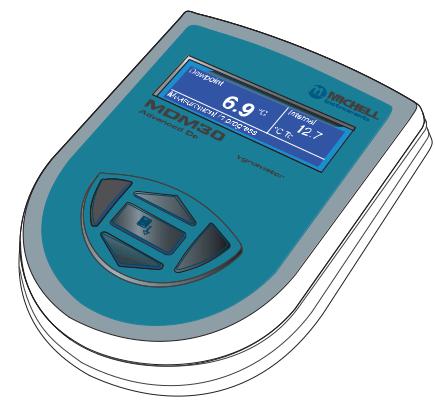
|
INTRODUCTION |
MDM300 I.S. User’s Manual |
Two versions of the instrument are available, an MDM300 (standard) version and an MDM300 I.S. (intrinsically safe) version.
This manual covers the MDM300 I.S. version only.
For information about the MDM300 contact your local Michell Instruments’ representative (contact information at www.michell.com).


 -I.S.
-I.S.


Figure 1 MDM300 I.S. Advanced Dew-Point Hygrometer
(for use in hazardous areas)
|
2 |
97213 Issue 5, October 2017 |
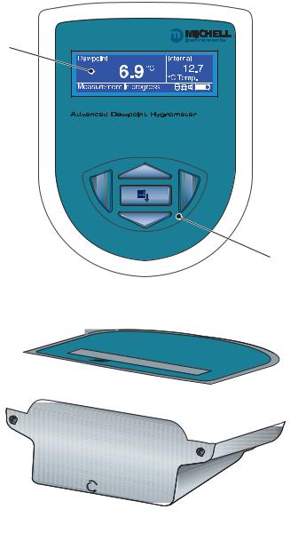
|
MDM300 I.S. User’s Manual |
INTRODUCTION |
1.1Controls and Indicators
The controls and indicators associated with the MDM300 I.S. instrument are located on the front panel of the instrument.
Connections to the MDM300 I.S. dew-point hygrometer, comprising the gas ports, battery charger input connector and input connector for the external sensor are all made to the top panel.
Figure 2 shows the layout of these controls and Table 1 describes their respective operational functions.
2


 — I.S.
1
.S.I- 

|
7 |
6 |
5 |
4 |
3 |
Figure 2 User Connections, Controls and Indicators

|
INTRODUCTION |
MDM300 I.S. User’s Manual |
|||
|
Item |
Panel |
Description |
||
|
1 |
Front |
Function keys. Refer to Section 1.2 for the details of these |
||
|
keys. |
||||
|
Instrument display, partitioned to show 3 main panels: |
||||
|
The primary display shows internal sensor parameters. |
||||
|
2 |
Front |
The |
secondary display indicates the external sensor |
|
|
parameter. |
||||
|
The status display area shows icons representing battery |
||||
|
charge state, initialization in progress, data logging in |
||||
|
progress, keyboard lock status and keyboard beep status. |
||||
|
Instrument ON/OFF switch. |
||||
|
3 |
Top |
NOTE: The instrument does not need be switched ON |
||
|
in order to charge the internal NiMH battery. |
||||
|
4 |
Top |
Gas Output port. Refer to Section 2.5. |
||
|
5 |
Top |
Gas Input port. Refer to Section 2.5. |
||
|
Analog input connector for external sensor. |
||||
|
By default, this signal is displayed in the secondary display |
||||
|
area but may be configured to be displayed as the primary |
||||
|
display. |
||||
|
6 |
Top |
If no external input is selected, the internal sensor |
||
|
temperature is shown, on the secondary display, by default |
||||
|
(refer to Section 3.4.6). |
||||
|
NOTE: The hinged rubber protection cover should be |
||||
|
kept closed when the connector is not in use. |
||||
|
Socket for connection of battery charger (located behind |
||||
|
secured cover). |
||||
|
Connection to the battery charger should |
||||
|
! |
always be made in a safe area — never in a |
|||
|
7 |
Top |
hazardous area environment |
||
|
The secured cover should be kept screwed on when the |
||||
|
connector is not in use. |
||||
|
! |
ONLY USE THE CHARGER PROVIDED |
|||
|
! |
Never allow the battery to fully discharge |
|||
Table 1 Controls and Indicators
|
4 |
97213 Issue 5, October 2017 |

|
MDM300 I.S. User’s Manual |
INTRODUCTION |
1.2Function Keys
The function keys, located on the front panel, are used to select operations from the menus and to select and enter parameter variables within those menu levels.
The function key described is shaded darker and the operation of the keys is as follows:
1.2.1Enter Key
The Enter key is used within the menus to highlight and select options and to accept entered values.
Operation of this key from the Main Display causes the Passcode entry page (for entry to the SET-UP Menu) to be displayed.
1.2.2Up () and Down () Keys
Within the SET-UP Menu and sub-menus these and keys are used to scroll down and highlight options.
Within sub-menu levels requiring the entry of alpha numeric values, these keys are used to change the values. Pressing the key once increases or decreases the selected field by one step. Pressing and holding the key will cause the selected field to be continuously increased or decreased until the key is released.
1.2.3Right () Key
Within sub-menu levels requiring the entry of alpha numeric values, this key is used to shift the insertion point right in the file name entry field.
From the Main Display, pressing this key moves to the Chart
Page.
From the Chart Page, pressing this key moves to the Logging
Pages.
1.2.4Left () / Escape Key
Within sub-menu levels requiring the entry of alpha numeric values, this key is used to shift the insertion point left in the file name entry field. As the insertion point is shifted to the left, the entry at the former position is deleted.
Within any menu or sub-menu level, pressing this key escapes to the previous menu above the current level.
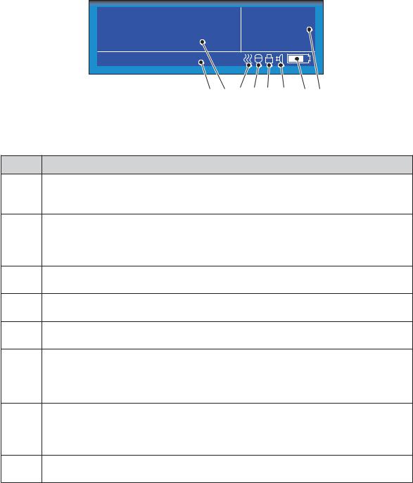
|
INTRODUCTION |
MDM300 I.S. User’s Manual |
1.3Instrument Display
The graphics display and the associated function keypad (Figure 2), form the operator interface of the equipment. Figure 3 shows all the elements of a typical display page after the instrument’s initialization period has completed.
Table 2 details the elements of the display:
|
8 |
7 |
6 |
5 |
4 |
3 |
2 |
1 |
Figure 3 Instrument Display
Item Description
Secondary display
1Shows reading from external sensor, if configured; or internal temperature if external sensor is not configured (refer to Section 3.4.6).
Battery charge indicator icon
2Flashes when the battery needs charging. A warning beep sounds when the battery charge level is critical — followed immediately by Shutdown Mode.
NOTE: The icon becomes animated when the charger is connected.
3Keyboard beep indicator
Indicates that the keyboard beep is switched on.
4Keyboard lock indicator
Indicates that the keyboard is locked.
5Datalog status indicator
Indicates that logging is enabled and running.
Sensor initializing indicator
6Indicates that the initialization process is in progress and that the sensor heating is on. The presence of this symbol is accompanied by Initializing internal sensor status message.
Primary display
7During normal operation, the internal sensor readings are shown in the primary display. If the external sensor has been configured then this reading can be shown in this display (refer to Section 3.4.6).
8Status message display area
Displays status and error messages.
Table 2 Instrument Display Descriptions
|
6 |
97213 Issue 5, October 2017 |
|
MDM300 I.S. User’s Manual |
INTRODUCTION |
1.3.1Display Units
The instrument can display the measured reading in the following units:
Absolute Humidity
•lb/MMscf
•g/m3
•g/m3 NG
Moisture Content
•ppmV NG
•ppmV
•ppmW (AIR, USER, H2, SF6, CO2 or N2)
Dew Point
•°C
•°F
•K
Relative Humidity (%)
Mixing Ratio
•g/kg (AIR, USER, H2, SF6, CO2 or N2)
To toggle between displayed units, press either the or key.
|
INTRODUCTION |
MDM300 I.S. User’s Manual |
1.3.2Status Display Indications
‘Initializing Internal Sensor’
This is displayed immediately after the instrument has been powered up, and indicates that the sensor is being heated up to accelerate equilibrium with the moisture in the sample gas. This has the effect of drying the sensor out, and results in the ‘undershoot’ seen in the first stage of the measurement process.
‘Measurement in Progress’
This is displayed after the sensor initialization has finished, and indicates that the sensor is running through the following initial measurement procedure:
1.Undershooting the dew-point
2.Making a first estimate
3.Running a QRA (Quick Response Algorithm), if necessary
Once the message has disappeared, this indicates that the instrument has finished its accelerated approach to the actual dew point. Depending on the conditions, it may continue to respond for a number of minutes more, before settling on (or tracking) the actual measured dew point.
Other Status Display Indications
|
Internal sensor |
Dew-point reading out of range (> +30 / < -120°C) |
||
|
error |
|||
|
Internal thermistor |
Sensor internal temperature reading out of range (> +100 / |
||
|
< -40°C) or |
|||
|
error |
Thermistor fault |
||
|
External sensor |
External Sensor Input out of range (< 4 mA / > 20 mA) |
||
|
error |
|||
|
Battery low |
Battery level low — recharge as soon as possible |
||
|
Battery |
low |
— |
Battery level critical — recharge immediately |
|
recharge now |
|||
|
Log finished |
Log file has reached the maximum of 10,000 logs and logging has |
||
|
been stopped |
|||
|
Internal sensor not |
Could not detect internal sensor on power up |
||
|
found |
|||
|
Default CONFIG file |
Config. file missing, new file created and default settings used |
||
|
used |
|
8 |
97213 Issue 5, October 2017 |
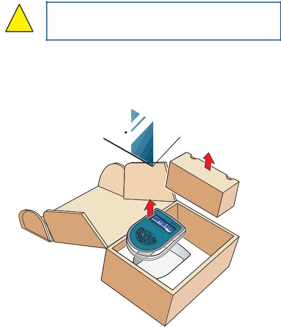
|
MDM300 I.S. User’s Manual |
INSTALLATION |
2 INSTALLATION
2.1Safety
It is essential that the installation of the electrical and ! gas supplies to this instrument be undertaken by qualified
personnel.
2.2Unpacking the Instrument
The MDM300 I.S. instrument is packed into a standard box and the method of unpacking is shown below:
|
I |
. |
Hygrometer |
|||
|
.S |
|||||
|
-PointManual |
|||||
|
MDM300 |
|||||
|
Dew |
|||||
|
Advanced |
User’s |
4 |
|||
|
3 |
Figure 4 Packing Method
1.Open the box (1) and unpack carefully.
2.Remove the MDM300 I.S. (2), the user’s manual (3) and the accessories box (4).
3.Save all the packing materials for the purpose of returning the instrument for re-calibration or any warranty claims.
4.If the optional carry bag has been ordered it will be located underneath the foam insert, in a cardboard box.
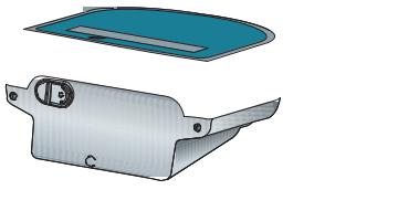
|
INSTALLATION |
MDM300 I.S. User’s Manual |
2.3MDM300 I.S. Accessories
The accessories for the MDM300 I.S. are shown in Figure 6. Items 1 to 7 are supplied as standard and item 8 is optional. Please check that all the standard components are present after unpacking. Report any shortages immediately.
1.Calibration certificate
2.User’s manual
3.Charger unit
4.Country specific mains lead
5.Gas Input/Output port adaptors
(three provided — two fitted to the instrument — see Figure 5)
6.Application Software CD
7.Quick-start card
8.Carrying case — made from anti-static materials suitable for use in hazardous areas (optional)
Three gas port adaptors are provided, two with a large bore orifice and one with a small bore orifice. Depending upon configuration, this permits the instrument to be run at either system pressure or atmospheric pressure and facilitates the connection of external flow monitoring and control.
NOTE: On delivery the two large orifice adaptors are fitted into the instrument’s gas ports (1 and 2) as shown in Figure 5. One small orifice adaptor is provided as a loose spare in the accessory pack (see Section 2.5).
.S.I —
Small orifice
Large orifice
21
Figure 5 Gas Port Adaptors
|
10 |
97213 Issue 5, October 2017 |
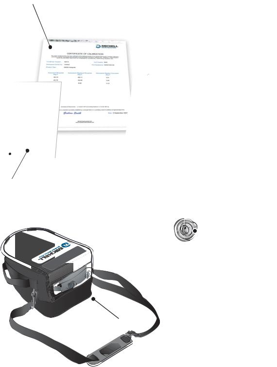
|
MDM300 I.S. User’s Manual |
INSTALLATION |
1
MDM300 & MDM300 I.S. Quick Start Guide
Typical MDM300 Sampling Arrangement
SAMPLE FLOW
 1
1
 2
2
3
4
VENT
1 Coalescing Filter
2Particulate Filter
3Inlet Flow Control Valve
4Outlet Flow Control Valve
HIGH PRESSURE! High pressure gases are potentially hazardous. Energy stored in these
! JDVHV FDQ EH UHOHDVHG VXGGHQO DQG ZLWK H[WUHPH IRUFH +LJK SUHVVXUH VVWHPV VKRXOG EH
DVVHPEOHG DQG RSHUDWHG RQO E SHRSOH ZKR KDYH EHHQ WUDLQHG LQ SURSHU VDIHW SUDFWLFHV
97244 Issue 02, July 2011
7
2
Hygrometer
. -I.S
|
4 |
. 1 |
||
|
Issue |
|||
|
97213 |
2013 |
||
|
June |
3
4
 5
5
Figure 6 Accessories
|
INSTALLATION |
MDM300 I.S. User’s Manual |
2.4Operational Requirements
Operational requirements are as follows:
|
Sample gas flow rate: |
0.2 to 0.5 Nl/min (0.5 to 1 scfh) |
|
Operating pressure: |
0 to 350 barg (0 to 5076 psig) |
2.4.1Environmental Requirements – MDM300 I.S. Instrument
Operating temperature range: -20 to +50°C (-4 to +122°F)
|
Humidity: |
0 to 100% RH (non-condensing) |
|
Altitude: |
Up to 2000m (6562 ft) |
2.4.2Charger Electrical Requirements
|
Charger supply voltage: |
100 to 240 V AC (+10%, -15%) |
|
50/60 Hz (±5%), 8 VA |
2.5Instrument Gas Connections
POSSIBLE INJURY! The tubing, valves and other apparatus ! attached to this instrument must be adequate for the
maximum pressure which will be applied, otherwise physical injury to the operator or bystander is possible.
Sample gas connections are made via the Gas In (2) and Gas Out (1) ports located on the rear of the instrument as shown in Figure 5.
The MDM300 I.S. is supplied with a large bore orifice fitting installed into the Gas In and Gas Out ports. These fittings have an 1/8” NPT female thread to allow the user to connect other components of their choice.
Atmospheric pressure or system pressure dew point can be measured depending on the configuration of the adaptor fittings as shown in Table 3.
For gas pressures outside the range 2.5 to 10 barg, the instrument requires external flow control components, as shown in Figure 8.
|
Dew point at |
Gas Inlet port |
Gas Outlet port |
Sample gas |
|
|
fitting |
fitting |
pressure |
||
|
Atmospheric |
Small bore orifice |
Large bore orifice |
2.5 to 10 barg |
|
|
(36 to 145 psig) |
||||
|
System |
Large bore orifice |
Small bore orifice |
2.5 to 10 barg |
|
|
(36 to 145 psig) |
||||
|
Either (using |
0 to 350 barg |
|||
|
other flow control |
Large bore orifice |
Large bore orifice |
||
|
(0 to 5076 psig) |
||||
|
components) |
||||
|
Table 3 |
Adaptor Fittings |
|
12 |
97213 Issue 5, October 2017 |
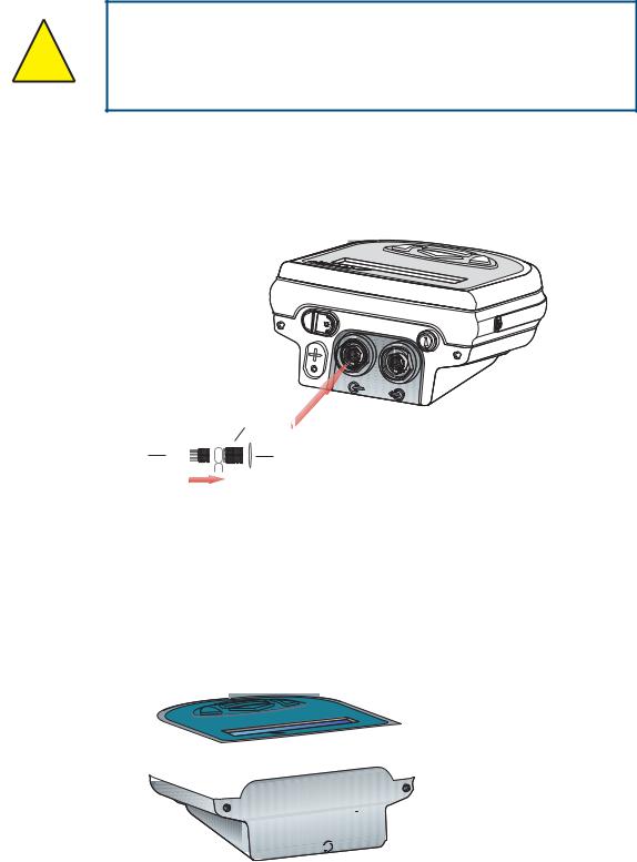
|
MDM300 I.S. User’s Manual |
INSTALLATION |
2.5.1Gas Inlet /Outlet Fittings
HIGH PRESSURE! High pressure gases are potentially hazardous. Energy stored in these gases can be released
! suddenly and with extreme force. High pressure systems should be assembled and operated only by people who have
been trained in proper safety practices.
Before making a measurement, the gas fittings should be attached to the instrument as shown in Table 3.
1.Fit the required orifice fittings with supplied bonded seals. Ensure bonded seals are correctly seated in recessed grooves.
PTFE tape here
h
Figure 7 Bonded Seal Fitting
2.Fit any other adaptors that might be required.
3.If the small bore orifice fitting is not being utilized then one of the optional application kits could be fitted (as shown below).
.S.I
Figure 8 Gas Coupling Examples for Atmospheric Pressure Measurement
NOTE: The application kit shown above (excluding the orifice fittings) is not supplied as standard, but is part of a range of kits which can be ordered from Michell Instruments, on request.
NOTE: The bonded seals used for the MDM300 I.S. are Dowty part number 400-228-4490-74 (from Michell Instruments, part number MDM300-DS).
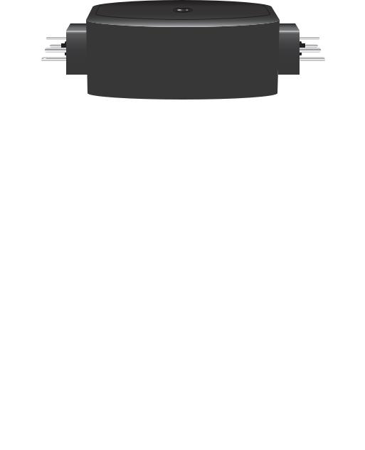
|
INSTALLATION |
MDM300 I.S. User’s Manual |
2.6Connect External Sensors
The MDM300 I.S. can be configured for connection to a Michell Instruments’ Easidew I.S. transmitter (ATEX Baseefa 06ATEX0330X, IECEx BAS06.0090X), via the MDM300 I.S. Remote Sensor Interface, when the Easidew I.S. transmitter is installed within a hazardous area.
The MDM300 I.S. Remote Sensor Interface is a passive device. The combined terminal parameters of the MDM300 I.S. and of the barrier used with the Easidew I.S. system must not exceed the input terminal parameters of the Easidew I.S. as specified in the System Drawing (System Certificate No. Baseefa 07Y0027).
To view any of these certificates go to: http://www.michell.com
 to Connect
MDM300 I.S.
REMOTE SENSOR INTERFACE
|
Connect to Easidew I.S. Sensor |
|
|
|
|
EASIDEW I.S. SYSTEM
Connect to
Figure 9 MDM300 I.S. Remote Sensor Interface
Refer to Appendix C (Hazardous Area Certification) for the MDM300 I.S. terminal parameters.
Figure 10 shows the connection of the MDM300 I.S. Remote Sensor Interface to the MDM300 I.S. and the Easidew I.S. transmitter.
|
HAZARDOUS AREA |
X |
||||||
|
REMOTE SENSOR |
h |
||||||
|
INTERFACE |
|||||||
|
W |
MDM300 I.S. |
Connectto |
W |
||||
|
toConnect .S.IMDM300 |
Connect to Easidew I.S. Sensor |
||||||
|
W |
REMOTE SENSOR INTERFACE |
W |
|||||
|
W |
W |
||||||
|
20mA0Hz28Vdc |
|||||||
|
EASIDEW.S.IDewPointTran |
|||||||
|
,5NmEly,CambsUK |
|||||||
X SAFE AREA
EASIDEW I.S. SENSOR BARRIER ASSEMBLY
SYSTEM CERT
Baseefa 07Y0027
h
MDM300 I.S.
Figure 10 External Sensor Connection
|
14 |
97213 Issue 5, October 2017 |