
-
Contents
-
Table of Contents
-
Troubleshooting
-
Bookmarks
Quick Links
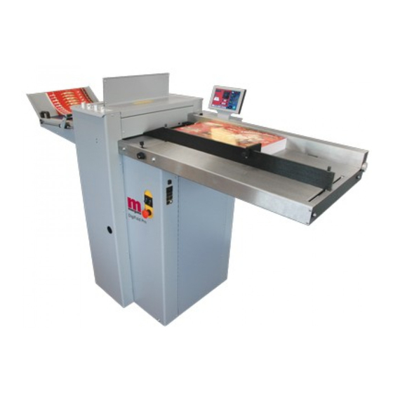
DigiFold Pro
DOCUMENT
FOLDING MACHINE
OPERATORS MANUAL
Morgana Systems Limited
Telephone:
( 01908 ) 608888
Website: www.morgana.co.uk
ISSUE 3
United Kingdom
Facsimile: ( 01908 ) 692399
March 2011
174-025
Related Manuals for Morgana DigiFold Pro
Summary of Contents for Morgana DigiFold Pro
-
Page 1
DigiFold Pro DOCUMENT FOLDING MACHINE OPERATORS MANUAL Morgana Systems Limited United Kingdom Telephone: ( 01908 ) 608888 Facsimile: ( 01908 ) 692399 Website: www.morgana.co.uk March 2011 ISSUE 3 174-025… -
Page 2: Table Of Contents
INDEX INTRODUCTION & SPECIFICATION The Morgana DigiFold Pro PAGE SAFETY Do’s & Don’ts THE Digifold Pro Labeled Photograph THE SWITCH PANEL Detailed diagram and description Features on the switch panel OPERATING THE DigiFold Pro Adjusting the Papergate Setting the Suction Slot…
-
Page 3
DigiFold Pro INDEX REPLACING CREASING BLADE SETS Installing new blade sets PAGE 38 Spare Blades PERFORATING Equipment, Spares Setting the machine Recommended Position of the Drive Wheels and Hubs REMOVING PAPER JAMS TROUBLE SHOOTING Paper crease out of square Crease Position Inaccuracy… -
Page 4
DigiFold Pro INTRODUCTION AND SPECIFICATION Digifold Pro is a registered trade mark of Morgana systems Ltd. The unique patented creasing and folding system, makes it possible to fold most delicate stocks from 0.11mm, up to 0.4mm thick. The DigiFold Pro… -
Page 5: Safety Do’s & Don’ts
DigiFold Pro Safety Do’s & Don’ts Safety Do’s & Don’ts REGLES DE SECURITE : « A FAIRE » ET « A NE PAS FAIRE » Do — read this operator manual fully before operating the machine. Lire ce mode d’emploi avant d’utiliser la machine.
-
Page 6
Warning Labels Do — be aware of any finger traps and rotating parts when operating the machine. Attention au risque de se coincer les doigts, et aux pièces en mouvement lors du fonctionnement de la machine. Do — read this operator manual fully before operating the machine. Lire ce mode d’emploi avant d’utiliser la machine. -
Page 7
DigiFold Pro DigiFold Pro DOCUMENT FOLDING MACHINE Key to photograph below Delivery assembly 6 Air Separation Knob 11 Paper Gate Vacuum bleed knob 7 Adjustable side lay 12 Top cover Suction slot knob 8 Back stop 13 Touchscreen Switch panel… -
Page 8
The Switch Panel The Switch Panel houses the Compressor switch, System switch, and an industry standard Emergency Stop switch which will stop all power going to the machine when activated. THE SWITCH PANEL Compressor Switch System Switch Emergency Stop Switch Page 8 FOLDING… -
Page 9: Features On The Switch Panel
DigiFold Pro The Switch Panel Features on the Switch Panel System switch When activated the system switch will operate the motors in order to begin the creasing sequence. Compressor switch Allows the operator to switch off the compressor unit in order to utilise the machine to manually feed sheets.
-
Page 10: Operating The Digifold Pro Adjusting The Papergate
Operating the DigiFold Pro Adjusting the Paper Gate Set the height of the Paper Gate to approximately two thicknesses of paper, by turning the disc j. An excessive gap is a most likely cause of double sheet feeding. This setting is only intended as a guide, for instance, sheets with an upward curl will require this setting to be increased.
-
Page 11: Setting The Vacuum Bleed
DigiFold Pro Operating the DigiFold Pro Setting the Vacuum Bleed Situated on the front of the feed table, the Vacuum Bleed Knob is used to allow more control of the suction on the vacuum drum. When light weight paper is being fed through the machine turn the knob clockwise to reduce the possibility of marking, or damage to the leading edge of the paper.
-
Page 12
Operating the DigiFold Pro Setting the positions of drive wheels and hubs It is important that the drive wheels and drive hubs, on the roller shafts, are arranged across the width of the media being creased; this is done to ensure that the media is accurately driven and supported through the rollers. -
Page 13
DigiFold Pro Operating the DigiFold Pro BLANK PAGE SYSTEM Page 13… -
Page 14
Select the green tick icon only if you have been trained to operate this machine. If you have not been trained to operate this machine and you select the green tick icon, Morgana Systems Ltd accept no responsibility for personal injury, damage to the machine or damage to materials being processed by the machine. -
Page 15: Paper Settings
DigiFold Pro Operating the DigiFold Pro Setting Pages. Paper settings Page Fold Selection — For quick setting of fold positions on standard size sheets. Highlighted fold is type currently selected, other folds may be selected. Paper Type — As a guide choose as Currently selected fold is shown in the status area.
-
Page 16
Operating the DigiFold Pro Batch size Selection. Pre-set Batch sizes for quick insertion. Paper Thickness input Paper Thickness Selection. Pre-set Paper Thickness sizes for quick insertion. Page 16 FOLDING… -
Page 17: Roller Gap Set & Tilt Mechanism
DigiFold Pro Operating the DigiFold Pro Roller Gap Set & Tilt Mechanism Page. To get to the roller gap setting page click the lower tab Roller gaps may be in the range of 0.05mm to 1.5mm, with increments of 0.05mm…
-
Page 18
Operating the DigiFold Pro The gap settings (Gap 1, Gap 2 & Gap 3) can then be adjusted by rotating the Roller Gap Set Knobs (see FIG 10.1 on page 10). IMPORTANT. When setting roller gaps, you must first adjust the gap to a value greater than that required and then decrease the value to the required setting. -
Page 19
DigiFold Pro Operating the DigiFold Pro Setting the Blade Tilt Mechanism The blade tilt mechanism has been designed to compensate for when the creasing position on the sheet is not square. This could be due to an inaccuracy in the media or if the blade tilt mechanism has been incorrectly set. -
Page 20: Creases In ‘Set By Fold’ Mode
Operating the DigiFold Pro Crease Settings Pages. To get to the crease setting page click the lower tab from the status area. If you have selected a predefined standard Fold Type from the paper settings page ± 0.1mm the crease positions will be set for you. These positions can be fine tuned by increments by pressing the arrow buttons for each crease.
-
Page 21: Creases In ‘Set By Position’ Mode
DigiFold Pro Operating the DigiFold Pro Creases in ‘Set By Position’ mode. Arrows may be selected Crease position — On selection the to increase or decrease status area is replaced with a The page size in 0.1mm calculator for inputting new values, a increments maximum of 9 creases can be added.
-
Page 22
Operating the DigiFold Pro Turn crease on/off. Status shows creasing off Greyed out area indicates icon the trim is not selectable This button toggles creasing on & off. Individual deletion of crease confirmation screen. Crease 230 mm from lead edge will be deleted. -
Page 23: Folds In ‘Set By Fold’ Mode
DigiFold Pro Operating the DigiFold Pro Fold Settings Pages. To get to the Fold setting page click the lower tab from the status area. If you have selected a predefined standard Fold Type from the paper settings page ± 0.1mm the crease positions will be set for you.
-
Page 24: Folds In ‘Set By Position-‘ Mode
Operating the DigiFold Pro Folds in ‘Set By Position’ mode. Fold distance from lead edge for knives (K1 & K2) increments of 0.1mm K1 deflect button K1 micro adjust selected Clicking this icon switches K1 in deflect position. deflect off &K1 returns to its original position.
-
Page 25
DigiFold Pro Operating the DigiFold Pro NOTES:- If a crease position is adjusted, the fold will move with it. If a fold position is adjusted, then only the fold will move. Adjust a fold only if the fold appears to be giving an out of square result or cracking appears. -
Page 26
Operating the DigiFold Pro Example of Set by Position. Paper Length = 350mm (13.8”) Feed Direction Leading Edge Crease 1 Crease 2 Crease 3 SETTINGS Fold 1 Fold 2 Crease 1 = 97.0mm (3.8”) Crease 2 = 179.0mm (7”) Crease 3 = 260.0mm (10.2”) All dimensions are from the leading edge of the paper Fold 1 = 179.0mm (7”) -
Page 27: Delivery Settings
DigiFold Pro Operating the DigiFold Pro Delivery Settings Page. To get to the Delivery setting page click the lower Roller position may be micro adjusted by clicking here. Shingle may be micro adjusted by clicking here. Roller adjustment calculator. Shingle adjustment calculator.
-
Page 28
Operating the DigiFold Pro Setting the Delivery Conveyor System. WARNINGS:- 1. The Machine will start if the delivery unit is not in its up position. 2. If the delivery is turned off the roller will feed to the far end of the belt conveyor and park there until turned on again. -
Page 29: Status Screen
DigiFold Pro Operating the DigiFold Pro Status Screen. Green icon indicates settings are Clicking in this area will take Clicking in this area will take saved — a red icon would show that you to the paper setting you to the store page settings have changed but page.
-
Page 30
Operating the DigiFold Pro Run Job. Click to run machine. System Switch Not On. Click to confirm System switch is on & then click run button again The machine running screen will appear. Run count Batch Count Job Count Click to stop machine. -
Page 31: Setting The Machine To Operate In Manual Sheet Feed Mode
DigiFold Pro Operating the DigiFold Pro Setting the machine to operate in manual sheet feed mode In order to feed heavy stock, very small or very large sheets, embossed or even irregular shaped sheets, it may be necessary to feed the sheets manually.
-
Page 32: Store
Operating the DigiFold Pro Store Pages. To get to the Store setting page click the lower tab from the status area. New Jobs. Having set up your job you can give the job a name and save it to a store. You can also retrieve previously saved jobs, modify them or delete jobs you no longer require.
-
Page 33
DigiFold Pro Operating the DigiFold Pro Save confirmation screen. To confirm saving of job click here. Search for current jobs to load or modify. You can search for jobs by clicking the search icon , this will bring up the search keyboard for text input. -
Page 34
Operating the DigiFold Pro Loading job confirmation screen. To cancel loading of Job press here To confirm loading of Job press here Loaded job may be modified and then re-saved as the same job name. Overwrite job confirmation screen. To cancel overwrite of Job press here. -
Page 35: Tools Menu
DigiFold Pro Operating the DigiFold Pro Tools Menu. To get to the Tools page click the lower tab Click on Up Arrow to put Anvil into Top Dead Centre position Inch paper in direction (TDC) of arrow to clear jams…
-
Page 36
Operating the DigiFold Pro BLANK PAGE Page 36 FOLDING… -
Page 37
DigiFold Pro The Blade Assembly Adjusting the blade pressure (no paper required) 1. (i) Switch the power ‘on’ by turning the Emergency stop button clockwise to release the safety latch. (ii) Select the Tools tab at the bottom of the touch screen, the display will change to that shown below. -
Page 38
Replacing Blade Sets 1. Before removing the blade assembly, ensure that the lower blade / anvil is at ‘Top Dead Centre’, see page 37. 2. Lift the top cover. 3. Using a 5mm allen key, remove the two socket head screws, one each end of the Blade Set, as shown in FIG 32.1 below. -
Page 39
DigiFold Pro Replacing Blade Sets 6. Insert the Blade Extractor Tools, one at each end of the Blade Set, as shown in FIG 33.1 below. Note The Position of The Blade Extractor Tool Under The Lip of The Blade Adjuster Assembly FIG 33.1… -
Page 40
Replacing Blade Sets 8. Slide the blade assembly out of the creasing unit and lay it on a flat surface. 9. Slide the blade adjustment cams and the blade adjustment assemblies away from the dowels located in the ends of the blades / anvils as shown in FIG 34.1 below. FIG 34.1 10. -
Page 41
Blade sets are individually set for each machine at the point of manufacture. Replacement Blade sets will therefore need to be set up by a factory trained service engineer. Do not attempt to use a Blade set from another Digifold Pro. SYSTEM Page 41… -
Page 42
Perforating Once the machine is set-up, the Machine can be used to perforate or crease. Notes 1. Perforating and creasing can be carried out simultaneously. However, if any adjustment is made to the roller tilt mechanism in order to compensate for the perforation line being ’out of square’, this may effect the accuracy of the crease. -
Page 43: Setting The Machine
DigiFold Pro Perforating All of the blades and anvils are supplied with fixings. *Perforator stripper Standard Part Number 177-05-01 *It is recommended that for multiple perforations, a separate perforator stripper is used for every perforating blade set fitted in the creasing unit.
-
Page 44
Perforating 12. Slide the drive hub towards the perforating drive wheel until there is a clearance of 0.5mm (0.020”). 13. To prevent damage to the blades or the anvils, do not force the drive wheel against the hub. 14. Fix the perforator stripper adjacent to the drive wheel and blade as shown. 15. -
Page 45: Removing Paper Jams
DigiFold Pro Removing Paper Jams Removing Paper Jams In the event of a paper jam occurring, whilst running the machine, follow the steps described below to allow access to remove the jammed paper. 1. Unlock and lower the delivery unit, open the top cover and the perforator unit; see FIG 39.1 below.
-
Page 46
BLANK PAGE Page 46 FOLDING… -
Page 47: Crease Position Inaccuracy
DigiFold Pro Trouble Shooting Paper crease out of square Check that the sheets are all square and exactly the same size before loading the stack on to the table. Check that the adjustable side lay has been correctly positioned ie. No further than 0.5mm (0.020”) from the paper stack.
-
Page 48: Machine Will Not Start
Trouble Shooting Machine will not start Check the power supply to the machine. Check that the emergency stop button has been released. Check that the top cover is down. Check that the perforator assembly is in its closed position. Check that the delivery unit is in the up position, and located correctly, (the machine will not start if the delivery unit is not in its up position).
-
Page 49: Using The Correct Blade Set
DigiFold Pro Trouble Shooting Using the Correct Blade Set. Two Blade sets are supplied with the machine. The Standard Blade set is suitable for material thicknesses of 0.25mm (0.010”) and greater. The Narrow Blade set is suitable for material thicknesses of 0.25mm (0.010”) and smaller.
-
Page 50: Paper Crunch
Trouble Shooting Error Screens Sheet did not arrive. If the machine stops and error message 01 is displayed on the touch screen, this indicates that the paper did not arrive at the end of the suck process; so the machine timed out.
-
Page 51: Blade Busy
DigiFold Pro Trouble Shooting Error Screens (Continued) Blade Busy If the machine stops and error message 05 is displayed on the touch screen, this indicates that the blade is busy. Try to operate the machine again, If this fails it is advised to contact a Service Engineer.
-
Page 52: Flying Home Failure
Trouble Shooting Error Screens (Continued) Flying Home Failure If the machine stops and error message 08 is displayed on the touch screen, this indicates that the home signal was missed during creasing. Check that the blade pressure is not too high. Clip 1 NOT clear (Back Sensor) If the machine stops and error message 09 is displayed on the touch screen, this…
-
Page 53: Clip 2 Not Blocked
DigiFold Pro Trouble Shooting Error Screens (Continued) Clip 2 NOT Blocked (Top Sensor) If the machine stops and error message 12 is displayed on the touch screen, this indicates that the sensor did not see the paper at the correct time.
-
Page 54: Trouble Shooting
Trouble Shooting Recommended weekly operator maintenance Clean all sensors. The lead edge sensor housing is located on the layedge side of the machine between the input roller shafts. With a slim brush the sensors can be cleaned when required. Pass the brush under the ball holder and push through until it passes the infeed rollers.
-
Page 55
DigiFold Pro BLANK PAGE SYSTEM Page 55… -
Page 56: Dispatch Kit
170-95-02 DISPATCH KIT ITEM PART NUMBER DESCRIPTION OPERATORS MANUAL — 174-025 DigiFold Pro 90-018 ROLLER CLEANING KIT 650-040 POWER CORD C19 UK 16A 2.5m 170-009-01 BLADE REMOVAL TOOL 601-167 DIGITAL THICKNESS GAUGE SCREW — SOCKET CAP HEAD — M3 x 6 LG…
-
Page 57: Accessories And Options
NARROW SHEET KIT 173-169-01 ETHERNET KIT 176-213-03 DYNAMIC BLADE SET — ULTRA NARROW 178-01-02 STACKER ASSEMBLY — DIGIFOLD PRO ACCESSORIES..OPTIONS..May be obtained from ..May also be obtained and your dealer and fitted to your fitted by your dealer. You should…
-
Page 58: Recommended Spares
RECOMMENDED SPARES PART NO. DESCRIPTION 125-21-02 Dual Stepper Driver Board 125-25-01 Small Stepper Driver — High Power 174-06-01 Small Stepper Driver — Low Power 174-01-02 Controller PCB Assembly + Chip 174-19-01 RS232 Adaptor PCB Assy. 75-472-01 Mini ITX Motherboard (Configured) 126-059-02 Link — Paper Guide 128-026-03 Delivery Belt…
-
Page 59: Recommended Spares
DigiFold Pro RECOMMENDED SPARES PART NO. DESCRIPTION 172-05-01 Paper Gate Assembly 175-21-01 Vacuum Roller Assembly 176-02-01 Blade Adjuster Assembly 176-081-01 Worm Wheel — Gap Set 176-213-01 Dynamic Blade Set — Narrow 176-213-02 Dynamic Blade Set — Standard 177-01-01 Perforator Assembly…
-
Page 60
MACHINE CALIBRATION HISTORY Serial Number:- Date:- Total Count:- Vac Suck Trim Vac Park Trim Stretch Lead Edge Trim Follow Stretch Del. Roller Trim Knife 1 Trim Knife 2 Trim K1 Deflect Trim K2 Deflect Trim K1 Travel K2 Travel Date:- Total Count:- Vac Suck Trim Vac Park Trim… -
Page 61: Fuse Positions & Ratings
DigiFold Pro FUSE POSITIONS & RATINGS (POSITION ET CLASSIFICATION DES FUSIBLES) PSUs (24V & 48V) PSU (5V / 24V) (FUSIBLE PSUs (24 V & 48 V) (FUSIBLE PSU (5V/24 V) T6.3AH 250 (681-019) F3.15AH 250 (613-023) SPARE FUSE ANTI-STATIC UNIT…
-
Page 62
PRODUCT RECYCLING & DISPOSAL European Union Disposal Information for Commercial Users Application of this symbol on your equipment is confirmation that you must dispose of this equipment in compliance with agreed national Procedures. In accordance with European legislation end of life electrical and electronic equipment subject to disposal must be managed within agreed procedures. -
Page 63
DigiFold Pro SYSTEM Page 61…

Технические характеристики:
Модель
DigiFold Pro
Максимальный формат
900 х 385 мм
Производительность
до 6000 А4 в час
Стоимость
звоните, будет СКИДКА
Наличие
уточняйте у продавца
- Data Sheet
Отправить заявку
Описание
MORGANA DigiFold Pro – уникальная машина, которая сочетает в себе функции биговки и фальцовки. Возможность пробиговать и автоматически сложить изделие, сделанное на плотной бумаге, делает эту машину незаменимой. Запатентованные компанией Morgana технологии биговки и фальцовки, высокая скорость работы и большой формат позволяют использовать эту машину, как в цифровых, так и в офсетных типографиях.
Соединив в одном устройстве функции биговки и фальцовки, компания MORGANA создала простой в обращении и обслуживании инструмент для обработки отпечатанной продукции. DigiFold Pro одинаково эффективен при работе с тонерными отпечатками, материалами со сложной структурой, заламинированными отпечатками и материалами высокой плотности. Эта машина позволяет автоматизировать участок послепечатной обработки и сократить количество ручного труда, а следовательно, брака.
Обработка цифровых отпечатков обычно вызывает сложности из-за того, что тонерный слой на отпечатке может растрескиваться по фальцу или на нем появляются полосы и царапины при фальцовке с помощью обычных фальц-кассет.
Также все изделия из мелованной бумаги плотностью свыше 160 гр/кВ. м. должны быть предварительно пробигованы перед фальцовкой для предотвращения излома поверхностного слоя мела.
Эти проблемы решены в MORGANA DigiFold Pro, что расширяет возможности послепечатной обработки.
С помощью MORGANA DigiFold Pro можно, например, за одну операцию получить бигованную и сфальцованную открытку на плотной бумаге. Владельцам офсетного печатного оборудования будет интересна высокая скорость работы MORGANA DigiFold Pro — 6000 А4 в час (независимо от количества бигов на листе) и большой рабочий формат – до 700 х 385 миллиметров. Среди преимуществ MORGANA DigiFold Pro нужно отметить возможность выполнения нескольких операции за один проход: биговка и фальцовка, биговка и перфорация, что позволяет на выходе получать полностью готовую продукцию (приглашения, буклеты-раскладушки, открытки, рекламные проспекты и т.п.). Машина позволяет выполнять следующие виды сложений: пополам, письмом, концертина, воротами, закрытыми воротами, инженерное, двойное параллельное.
В MORGANA DigiFold Pro используются две самые успешные технологии, разработанные компанией MORGANA : биговка «нож+матрица» и фальцовка с помощью «летающих ножей». Биговка с использованием ножа и матрицы DynaCrease позволяет сохранять скорость постоянной, независимо от количества бигов на листе. Фальцовка с помощью уникальных «летающих ножей» позволяет складывать материалы плотностью до 400 г/м2.
Для обеспечения стабильной подачи и повышения производительности при работе с цифровыми или мелованными материалами в Morgana DigiFold Pro используется система вакуумной подачи бумаги с воздушным разделением стопы, боковым равнением и возможностью дозагрузки автоподатчика «на ходу».
MORGANA DigiFold Pro можно легко интегрировать в автоматизированную систему управления рабочими потоками, благодаря поддержке стандарта JDF.
Машина стандартно поставляется с перфорационным диском для работы с плотными материалами — 28T SLITTER PERFORATOR BLADE (№ 1-99-12), позволяет сохранять в памяти машины до 9 часто используемых программ работы.
Преимущества Morgana DigiFold Pro:
- Биговка и фальцовка в одном устройстве
- Решение проблем с растрескиванием тонера на фальце или повреждением при сгибании поверхности фактурных или мелованных бумаг
- Работа с материалами плотностью до 400г/м2
- Работа с ламинированными материалами
- Биговка и перфорация за один проход
- Заменяет несколько «ручников»
- Поддержка стандарта JDF
- Высокая точность работы +/- 0,1 мм
- Стабильная и надежная подача материалов, благодаря вакуумной подаче
- Manuals
- Brands
- Morgana Manuals
- Folding Machines
- Digifold Pro CB
- Service manual
-
Contents
-
Table of Contents
-
Bookmarks
Quick Links
Digifold Pro
(CB/UL)
DOCUMENT
CREASING / FOLDING MACHINE
SERVICE MANUAL
Morgana Systems Limited
United Kingdom
Telephone: ( 01908 ) 608888 Facsimile: ( 01908 ) 692399
Website: www.morgana.co.uk
APRIL 2012
ISSUE 2
174-037
Related Manuals for Morgana Digifold Pro CB
Summary of Contents for Morgana Digifold Pro CB
-
Page 1
Digifold Pro (CB/UL) DOCUMENT CREASING / FOLDING MACHINE SERVICE MANUAL Morgana Systems Limited United Kingdom Telephone: ( 01908 ) 608888 Facsimile: ( 01908 ) 692399 Website: www.morgana.co.uk APRIL 2012 ISSUE 2 174-037… -
Page 2: Introduction
MORGANA DIGIFOLD Pro i ..Introduction The purpose of this manual is to explain the procedure for dis- mantling and re-assembly of the major assemblies on the Morgana Digifold machine. All the engineering adjustments are shown at the end of each relevant section.
-
Page 3: Identification
Digifold Pro Pan head and Cross-head countersunk screws all have metric Taptite threads and Pozi-drive recesses. Use No.2 point Pozidriv or Supadriv drivers for all screws M4 & above, and No.1 point drivers for M3 & below. WARNING WORK SHOULD BE CARRIED OUT BY A TRAINED AND COMPETENT ENGINEER AND ALL SAFETY PROCEDURES SHOULD BE ADHERED SWITCH OFF MAINS POWER BEFORE COMMENCING.
-
Page 4: Table Of Contents
INDEX Introduction ………………………………………………………………………..PAGE ¡ Introduction …………..2 ¡¡ Fasteners …………..2 ¡¡¡ Identification …………..3 New Machine Preparation ……….3 Section A …… Covers………….……………..Operator and Layedge Side Doors……. 9 Rear Cover…………..9 Control Cover and Top Cover ……..10 Delivery Conveyor Removal……… 11 Section B ………
-
Page 5
Digifold Pro PAGE Section H …..Optical Sensors…….……………………………………………………Cleaning Sensors — Creaser……..29 ……….Changing Sensors — Leading Edge……30 ……….Changing Sensors — Crunch……..30 ……….Changing Sensors — Folder Unit Clip 1&2….31 Section J ……Removing / Replacing Fold Knife Assembly……………….…… ….. -
Page 6
INDEX PAGE Section 15 ……..Sensors and Detectors …………65 Section 16 ……..Delivery Assembly …………..67 —————— Crease & Fold Setup Procedure ———————- Crease & Fold Setup Procedure Flow Chart ……… 73 Section 17 …..Primary Fold Setup …………… 74 Section 18 …..Crease Setup ……………. -
Page 7
Digifold Pro BLANK PAGE SYSTEM Page 7… -
Page 8
Digifold Pro DOCUMENT CREASING / FOLDING MACHINE Key to photograph below Delivery assembly Air separation knob Paper Gate Vacuum bleed knob Adjustable side lay Top Cover Suction slot knob Back stop Touchscreen Switch panel Fixed side lay Loading Table — Extension Air distribution knob Fuses (Optional) -
Page 9: Section A …… Covers
Digifold Pro SECTION A Covers: The Operator Side Door. The Operator Side Door cover which is situated adjacent to the operator, covers the Gap Set mechanism and Main Drive Pulley with its Belt. To remove this cover, first remove the two top fixing screws attaching the top plate, this must be lifted upwards to clear the gap set adjuster Knobs.
-
Page 10: Control Cover And Top Cover
SECTION A The Control Cover The Control Cover fixes to the front of the machine and supports the control cover door hinge, with the door attached. To remove completely wiil give very little access to anything, however opening the door beneath the feed table gives access to the main electric controls.
-
Page 11: Delivery Conveyor Removal
Digifold Pro SECTION A A.6 Delivery Conveyor To Remove the Delivery Conveyor the rear cover should be removed for access. Pivot the delivery down at 45 degrees using the handle on the end and turn the ‘delivery locking screw’ anti-clockwise to lock the delivery strut into this position. Shown in photo below.
-
Page 12: Section B
SECTION B B.1 Valve Setting. Removal of Butterfly Valve Assembly. The Butterfly Valve assembly is located inside the rear cover at the back of the machine. To remove the valve Assembly first unplug the cable from its control board. Remove the two pipe mounting clip plates (ITEM 6 on next page) so that the hoses can be detached from the valve.
-
Page 13: Valve Assembly Drawing
Digifold Pro SYSTEM Page 13…
-
Page 14: Section C
SECTION C REMOVAL OF CREASING UNIT: The creasing mechanism Assembly is located in the middle of the machine and can Be accessed by opening the top cover. First, access should be gained by removing the ‘Rear Cover Assembly’ and ‘Top Cover Assembly’.
-
Page 15
Digifold Pro When re-assembling the Tilt Control Mechanism, it is important to make sure that when you re-engage the upper and lower worms (C), the pins (A) on the upper and lower worm wheel assemblies (D) are in the same relative position as shown above. This will ensure the throw of each eccentric is in the same position at the top and the bottom. -
Page 16: Removal /Replacement Drive Belt
SECTION C REMOVAL/REPLACEMENT CREASING DRIVE BELT With the creasing mechanism out of the machine you can work on the bench to disassemble the unit. Remove the Blade/Anvil Assembly Unscrew the two countersunk head screws from the input and output guides and remove them.
-
Page 17
Digifold Pro BLANK PAGE SYSTEM Page 17… -
Page 18: Section D
SECTION D LOADING TABLE Removal of the Loading Table Remove the SideLay with the two locking Knobs. Remove the Choke Bleed Valve knob and the Choke Locking Knob. Remove the Choke Bleed Valve center shaft by unscrewing the soc. set screw beneath the loading table.
-
Page 19: Suction Drum Belt Removal/Replacement
Digifold Pro SECTION D SUCTION DRUM AND BELT REMOVAL REPLACEMENT Remove feed bed and side guide. Remove choke shaft by unscrewing the soc set screw from underneath, using a 2.5mm A/F allen key. Remove the bearing center support plate by unscrewing the two cap head screws. Remove suction drum and belt.
-
Page 20: Section E …….Infeed Roller Removal/Replacement
SECTION E REMOVAL/REPLACEMENT OF INPUT ROLLERS All side covers and the top cover should be removed to ease access to the infeed rollers. Remove the main creasing mechanism and tilt mechanism. TOP INPUT ROLLER Remove the lead edge sensor housing by unscrewing the two fixing screws from the rear of the machine and leave loose in situ.
-
Page 21
Digifold Pro Layedge Side Operator Side SYSTEM Page 21… -
Page 22: Section F …….Replacing The Touchscreen Assembly
SECTION F Replacing the Touch Screen Assembly Ensure the mains power is turned off but with the plug in the socket, this maintains an earth to reduce static damage. 1. Open the hinged Control cover located beneath the feed bed and open the rear cover to expose the mounting.
-
Page 23: Section G …….Electrics
SECTION G ELECTRICS: The PRO Control System. The Morgana PRO control system is essentially a computer system just like the PC you use at home. Unlike your Microsoft Windows PC, the PRO system uses a LINUX operating system and runs only one program, which is the machine control program for the particular machine that it is installed on.
-
Page 24: Removal/Refitting Control Pcb And Prog Board
SECTION G ELECTRICS: REMOVAL/REFITTING PCB’s REPLACEMENT OF MAIN CONTROL P.C.B. This PCB controls all functions of the machine and houses the Main Program PCB. The use of an antistatic wrist band should be used during work on the main control PCB. Switch the mains power off and disconnect from the mains supply.
-
Page 25: Installation Procedure
Digifold Pro Installation Procedure. 1. Note the current machine calibration settings. 2. Power down the machine and remove the power cord. 3. Change the USB Flash Drive (Red or Green depending on what is currently fitted). NOTE. It is important to choose the right colour in accordance with the machine you are upgrading.
-
Page 26: Removal/Replacement Itx Boards
SECTION G ELECTRICS: REMOVAL/REFITTING PCB’s ITX BOARD REPLACEMENT. The ITX mother board supplies the graphics to the touch screen display, to remove.- 1. Switch the mains power off. 2. Cut cable ties and unplug the all plugs. 3. Unscrew the four fixing screws attaching the board to the plate and remove from the machine.
-
Page 27: Removal/Replacement Stepper Drive Pcb
Digifold Pro SECTION G ELECTRICS: REMOVAL/REFITTING PCB’s REPLACEMENT OF STEPPER DRIVE BOARDS There is one Dual Stepper Driver Board, and three Single Stepper Driver Boards; which supply the drive motors with the correct power. These are located as above, and can be accessed in the same manner. Switch the mains power off and disconnect from the mains supply.
-
Page 28: Entering Engineers Tools
SECTION G DIAGNOSTICS and CALIBRATION TOOLS. To enter the engineers tools menu. Turn the Machine on. Insert the Engineers Plug into the Socket located at the rear of the machine. Select Tools on the Display and continue to select required tool. SET THE TOTAL COUNT TO ZERO.
-
Page 29
Digifold Pro SECTION H Cleaning Sensors Lead Edge Sensor The lead edge sensor housing is located on the layedge side of the machine between the input roller shafts. With a slim brush the sensors can be cleaned when required. Pass the brush under the ball holder and push through until it passes the infeed rollers, as can be seen in the picture below. -
Page 30
SECTION H Changing Sensors Lead Edge Sensor The Lead edge sensor assembly is positioned just after the input rollers and is housed in a black delrin machined block. To check the operation of this sensor, insert a piece of paper between the rollers and feed by hand until the sensor is covered, at which point the Red LED3 will illuminate on the main control PCB. -
Page 31
Digifold Pro SECTION H Changing Sensors on the Folder unit Clip Sensors. There are two sets of Clip sensors and both are located just after a set of fold rollers. They act as machine cutouts in cases of malfunction within the folding cycle. Clip 1 &… -
Page 32: Bottom Fold Knife
SECTION J REMOVING/ FITTING OF FOLD KNIFE ASSEMBLIES Remove the gap set assembly. Upper Fold Knife Remove the top curved guide by unscrewing the four posi pan head screws (2 each end). Loosen the sensor and allow to hang freely. Unscrew the two countersunk head screws (one each end) using a 4mm allen key and remove screws.
-
Page 33
Digifold Pro SECTION K Main Fold Rollers — Removal The folding unit has 3 main folding rollers that can be easily removed for replacement, the procedure for removing the rollers is as follows:- Rollers cannot be removed without removing the fold knives. Remove rear cover assembly and top guard. -
Page 34
SECTION K Main Fold Rollers — Removal Remove The 2nd Fold Roller Assembly as follows:- Remove the worm wheel from the shaft. Remove 3 off screws on access housing and 1 off on link plate. The roller assembly can now be withdrawn from the lay side of the machine. Remove The 1st Fold Roller Assembly as follows:- Remove 3 off screws on access housing. -
Page 35: Main Fold Rollers — Replacement
Digifold Pro SECTION K Main Fold Rollers — Replacement. The main rollers should be fitted into the folding unit in the reverse order of removal. Procedure for replacing the rollers is as follows:- Replace The 1st Roller Assembly as follows:- Insert the roller assembly into the frame from the operator side of the machine.
-
Page 36
SECTION L Perforator Unit Replacing the Gas Strut To Replace the gas strut first assemble the bottom shoulder bolt into its location and tighten using a 3mm allen key. With the dog point located in the shaft mark the shaft and the link plate such that you are able to realign the dog of the socket set screw when required. -
Page 37
Digifold Pro BLANK PAGE SYSTEM Page 37… -
Page 38
Digifold Pro Engineering Set-Up & Calibration Techniques Generally, Pre-Power Set-Up is made much easier if the Top Cover and the Entry Guard are removed. An adequate supply of DigiFold Pro Test Sheets (Part Number 170-004-01) should be made available for many of the set-up procedures. -
Page 39
Digifold Pro SYSTEM Page 39… -
Page 40: Section 1 ……………..Loading Table Alignment
Pre-Power Setup Procedure. The ‘Pre-Power Procedure’ does not require connection to the mains power supply so leave the machine disconnected if the covers have been removed. Loading Table Alignment:- The Loading Table Assembly effectively consists of the Loading Table itself, the Feed System & the Manifold Air Separation System which acts as the Fixed Sidelay for the initial alignment of the paper and therefore must be square to the input rollers.
-
Page 41
Digifold Pro It should be possible to visually check the parallel alignment of the lead edge of the 1.4. sheet with the Upper Input Roller. (See FIG.1.4). Fixed Side Lay (Manifold) Paper Upper Input Roller FIG.1.4 Lead Edge of Test Sheet If adjustment is required, loosen the two M8 Button Head Screws (see FIG.1.5 1.5. -
Page 42: Section 2 ……………..Dynacrease Alignment
Dynacrease Alignment:- The DynaCrease Unit has an adjustable Tilt Mechanism to enable Crease squareness adjustments to be made by the operator allowing for variations in Print & Paper Stock. To ensure that the operator has the full range of adjustment available, this unit needs to be centralized square to the Side Lay (&…
-
Page 43
Digifold Pro Remove the Balls from the Sidelay 2.2. Open the Input Roller gap fully by releasing the Locking Screw and using the 4mm 2.3. hexagon key to move it down towards the Loading Table. (See FIG.2.3 below). Locking Screw FIG.2.3 Operator Side Place a Test Sheet on the Loading Table with its Lay Edge against the Fixed Side Lay &… -
Page 44
If adjustment is required, loosen the two outside M8 Cap Head Screws securing the 2.6. Upper Pivot Block to the Frame, the two inside M8 Cap Head Screws securing the Lower Pivot Block to the top of the Blade Drive Stepper Motor Mounting Plate & the two outside M8 Cap Head Screws securing the Lower Pivot Block to the Frame. -
Page 45: Section 3 ……………..Belt Tension
Digifold Pro Belt Tension:- There are 5 Drive belts on the DigiFold Mechanism & 3 on the Delivery system. All Drive belts are XL Series Timing Belts of various widths and should be tensioned in accordance with the following notes. 3.1.
-
Page 46
Adjust the tension of the Blade Drive Belt on the DynaCrease Unit by loosening the four M5 3.5. fixings securing the Blade Drive Motor to the Stepper Mounting Plate. Access to these fixings is via the large clearance hole around the motor. Raise or lower the Motor until the correct tension is achieved &… -
Page 47
Digifold Pro 3.6. Adjust the tension of the Vacuum Drive Belt by loosening the four Cap Head fixings securing the Vacuum Drive Motor to the Vacuum Stepper Plate. Rotate the Motor about its top left hand fixing until the correct tension is achieved & tighten all fixings FIG.3.4A FIG.3.4B Vacuum… -
Page 48: Section 4 …………….Creasing Blade Installation
Creasing Blade Installation Creasing Blade & Anvil Sets are available in two sizes — Standard for sheets over 0.25mm thick & Narrow for sheets under 0.25. These figures are only a guide — good results can, in most cases, still be achieved outside a Blade Set’s range — see Trouble shooting Guide for more information.
-
Page 49
Digifold Pro 4.5. Place a Test Sheet on the Loading Table with its Lay Edge against the Fixed Side Lay & slide it through the open Input Rollers until the lead edge has passed through the DynaCrease Unit but not into the Fold Rollers. 4.6. -
Page 50
Input Transfer Shaft Gear Mesh The Lower Input Roller is driven by a pair of gears off the Input Transfer Shaft. To ensure Creasing accuracy, these two gears must mesh perfectly with little or no backlash. (See FIG.5.0 below). Loosen the Grub Screw which secures the Layside Access Housing for the Lower Input 5.1. -
Page 51
Digifold Pro Upper Input Roller — Setting the Parallelism & Pressure The Upper Input Roller is gear driven from the Lower Input Roller & should be adjusted for parallelism & pressure to ensure sheets are correctly aligned and controlled On the Layside end of this roller, there is an eccentric housing which enables adjustment. The housing is secured to the shaft using two M5 flat tip set screws. -
Page 52
FIG.6.1.B Shaft Flats 80gsm Test Strips Adjust the Layside Housing, using the shaft flats on the operator side, until a light 6.2. pressure is felt on the operator strip & then temporarily tighten one of the housing set screws on the op side. (the top one). Now adjust the operator side housing, using the M5 cap head screw, to give a very 6.3. -
Page 53
Digifold Pro BLANK PAGE SYSTEM Page 53… -
Page 54: Section 7 …………….Fold Rollers — Setting The Parallelism & Pressure
Fold Rollers — Setting the Parallelism & Pressure There are four Fold Rollers, one of which is fixed (Ø45) and has no adjustments This roller acts as the datum for the remaining three Fold Rollers (Ø60) which all have parallelism & pressure adjustments to ensure sheets are correctly aligned and controlled On the Layside end of each roller is an eccentric housing which enables adjustment of the parallelism.
-
Page 55
Digifold Pro SYSTEM Page 55… -
Page 56
Perforator Assembly The Perforator Assembly also acts as an outfeed unit to ensure that sheets are successfully ejected onto the delivery. It is gear driven off the 3rd Fold Roller and held in position by a Gas Strut. (The assembly can be swung away from the paper path to make clearing paper jams easier. -
Page 57
Digifold Pro Swing the Perforator back up into its operating position, set roller gap 3 to be a loose 8.3. pull on an 80gsm strip and check the mesh between the Idler Gear on the Perforator Assembly & the Drive Gear on the 3rd (Top) Fold Roller. (remove the 4 securing screws to remove the cover for better access) The gear mesh can be adjusted by rotating the Layside eccentric Adjuster Cam after 8.4. -
Page 58: Section 9 …………….Setting The Fold Knives
Setting The Fold Knives. The Fold Knives are driven by a stepper motor and are controlled by a cam follower and cam profile. The position of the black delrin cam is critical as it controls the start & stop positions of the Fold Knives.
-
Page 59
Digifold Pro downwards until the jig assembly fits correctly, adjust the 9.4. Rotate the Delrin cam eccentric shaft if required, tighten the two cap head screws on the ends of the eccentric shaft. Remove the Right Hand Shoulder Bolt from the Setting Jig, rotate the Jig (and the Knife 9.5. -
Page 60: Section 10 …………..Adjusting The Top Cover Safety Switch
10. Adjusting The Top Cover safety Switch 10.1. Open layside door. 10.2. Loosen the two fixings on the switch. 10.3 Adjust the switch position until lifting the top cover switches the machine when lifted by 6mm — 10mm. Page 60 CREASING / FOLDING…
-
Page 61
Digifold Pro SYSTEM Page 61… -
Page 62
Powered Setup Procedure. The «Powered Set-Up Procedure» does require connection to the Mains Power Supply so please ensure that all Covers & Guards are replaced & secure before proceeding. Adjustments to the Control System & Circuit Boards should only be carried out by fully trained & qualified personnel. -
Page 63: Section 12 ………….Fold Roller Gap Potentiometers
Digifold Pro Fold Roller Gap Potentiometers:- The Fold Roller Gaps are controlled by a mechanism which uses potentiometers to measure their positions. This information is then available to the Operator on the Gap Set Screen. These 3 Pots, which are located at the bottom of the Gap-Set Mechanism on the Operator Side of the machine, will all require calibrating:- Enter the Gap-Set Screen by operating the Touch screen.
-
Page 64: Section 13 ………….Dynacrease Tilt Potentiometer
DynaCrease Tilt Potentiometer:- The Dynacrease Tilt is controlled by a mechanism which uses a potentiometer to measure its position. This information is then available to the Operator on the Main Display Screen. This Pot, which is located at the bottom of the Tilt Mechanism on the Operator Side of the machine, will require calibrating:- Remove the Balls from the Sidelay.
-
Page 65: Section 15 …………Sensors And Detectors
Digifold Pro Repeat this procedure from 14.3 until the desired result is achieved and then 14.5. return to the Run Screen. With the motors running, operate the Compressor Switch to start the Compressor. 14.6. From the Run Screen start the Vacuum Drum & Suction. Hold a Test Sheet over the drum (do not allow the sheet to be fed) &…
-
Page 66
Crunch Sensor uses a beam projected across the machine just in front of the blade and above the paper path, when the beam is broken the machine will stop. The receiver is housed in the Side Plate of the machine and is on the Operator Side, whilst the transmitter is housed in the Side Plate of the machine on the Lay Side. -
Page 67: Section 16 …………Delivery Assembly
Digifold Pro Delivery Assembly The Delivery Assembly is there to provide a moving platform for the processed sheets to collect onto once finished. It consist of 2 main components, the delivery belt, and the delivery roller. Delivery Belt 16.1. To set the delivery Belt tension correctly it is imperative that the 2 ‘Roller Drive Belts’ are first loosened to prevent excessive loads to the drive roller bearings.
-
Page 68
Ensure the eccentric idlers are rotated to give little or no tension to the delivery 16.1.4. roller drive belts. Eccentric Idler (1 Each Side) FIG.16.1.4 Raise the delivery until it is fully up (ensure the gearbox is engaged first). 16.1.5. Turn on the ‘System Switch’. -
Page 69
Digifold Pro The ‘Delivery Roller’ drive belts need to be tensioned correctly (see previous section). NOTE — When adjusting the tension of the Lay Side ‘Delivery Roller Drive Belt’, notice that you are also providing the tension for the motor drive for this roller. Delivery Roller Squareness 16.2.1. -
Page 70
16.2.2. Delivery Potentiometer To position the roller correctly there is a potentiometer which provides the feedback to the processor. In order to set this correctly, you must follow this procedure; 16.2.2.1. Raise the delivery until it is fully up . 16.2.2.2. -
Page 71
Digifold Pro 6.2.2.5. Whilst holding the belt away from the pulley carefully rotate the potentiometer pulley until it reaches the end of its travel. 16.2.2.6. Continue to hold the belt away from the pulley and rotate the potentiometer pulley in the opposite direction for a full 5 turns (use a mark for reference if required). -
Page 72
NOTE — It may be necessary to re-tension the layside delivery roller drive belt. If so, do that now before proceeding to the next step. 16.2.2.10. See section 20. for calibration of the delivery roller. 16.3. Delivery Damping For the delivery to raise and lower correctly it is necessary to set the damping level of the supporting Gas strut that keeps it in position. -
Page 73
Digifold Pro SYSTEM Page 73… -
Page 74: Section 17 ………….Primary Fold Setup
Crease & Fold Setup Procedure Having completed the Pre-powered and Powered setup the digifold needs to have the crease and fold positions calibrated. This is primarily conducted using software adjustments within the ‘tools’ menu, however, during this process you may need to re- adjust the creasing matrix and Upper input roller in accordance with the descriptions stated below.
-
Page 75: Section 18 ………….Crease Setup
Digifold Pro Crease Setup Parallelism 18.1. The first part of this process confirms if the sheet steering has been corrected by checking the parallelism of the creases produced. If the creases are not parallel, then the upper input roller should be adjusted to compensate. (See FIG.18.1). Feed Direction Crease 3 Crease 1…
-
Page 76
NOTE — that although this procedure may have already been performed, it is critical the creases are parallel, even if this means the ‘Fold in Half’ test performed previously in the fold setup, is compromised slightly. To adjust the upper input roller follow this procedure. Loosen the two Operator side housing screws (M5 set screws). -
Page 77: Section 19 ………….Squareness
Digifold Pro Squareness Ensure the ’tilt’ is set to zero, and the ‘Dynacrease’ mechanism has been set square to the input rollers (see Pre-powered Setup). Using a test sheet, and keeping the sheet edge in contact with the fixed sidelay, manually feed the sheet through the input rollers and the creasing blades until the sheet can be seen just protruding from them.
-
Page 78
Crease Bias Crease bias is necessary to ensure the pre-programmed fold types give the best results. NOTE — The creasing matrix must be installed with the blade at the top, and test stock MUST be used. Do not used damaged test stock. To setup the crease bias, use the following procedure;… -
Page 79
Digifold Pro SYSTEM Page 79… -
Page 80: Section 21 ………….Delivery Roller
Calibration This is the final calibration procedure and closely follows the ‘Calibration’ flow chart. You must have completed all previous setup procedures leading up to this final calibration. If additional information is required for setting up the various crease and fold variations, please refer to the operators manual.
-
Page 81: Section 24 ………….Deflect Adjustments
Digifold Pro Deflect Adjustments The deflect trims need to be calibrated to allow the sheet to pass through the machine without damaging the lead edge. 24.1 K1 Double Deflect Trim In the tools menu Conduct this test with K2 turned off using the ‘Tools’ menu. If marking occurs on K1 then follow these general rules.
-
Page 82: Section 25 ………….Follow Stretch
Follow Stretch For creases that take place and don’t allow for the creasing blades to stop in between, an extra setting is required to account for roller diameter variations. Setup ‘Crease Only’ at 100, 170, 240, 310 and 370. Check the crease positions are pitched out correctly.
-
Page 83
Digifold Pro Section M Trouble Shooting Creasing Fault Reason Solution Erratic register of Too heavy crease profile. Adjust Blade depth to the creaser lower the pressure. Roller gap settings incorrect check with 80 gsm. adjust. (better to set tighter to drive) Damaged roller surface. -
Page 84
FAULT:- ‘NO SYNC’ appears on touchscreen. (Machine will not boot up). 1. CHECK THE ATX POWER SUPPLY AS FOLLOWS:- (i) Disconnect the 20/24 way ATX power supply connector from the ITX Motherboard. (ii) Using a piece of tinned copper wire, short out the GREEN and BLACK wires of the connector as shown in FIG.1 below FIG.1 TINNED COPPER WIRE LINK… -
Page 85
Digifold Pro PINS 3 & 4 FIG.2 IMPORTANT RECYCLING NOTE:- The ITX mother board has a lithium battery fitted, the board together with its battery must be in compliance with agreed national Procedures Please contact your local disposal recycled authority for information CAUTION. -
Page 86
Check 500mA fuse, below the Mains Input connector (See Page 90). IMPORTANT. If this fuse has blown replace it must be replaced with a T500mA fuse, Morgana part number 681-020. Is there a V DC output from the ATX PSU? (See page 84). Replace the ATX PSU. -
Page 87
Anti-static Transformer. FUSE YELLOW ORANGE T315mA Morgana Systems Ltd PUMP OVERLOAD BOARD WHITE WHITE If this fuse has blown it must be replaced with a T315mA fuse, Morgana part number 681-011. For Error messages see Operators Manual SYSTEM Page 87… -
Page 88
Section N Page 88 CREASING / FOLDING… -
Page 89
Digifold Pro 2 PSU ASSY. (76-272) 21 ENGINEERING LEAD (144-116) 3 DRIVE SIGNAL LEAD (173-56-01) 25 SENSOR BAR ASSY. (175-11-03) 4 BLADE SIGNAL LEAD (76-269) 26 SENSOR BAR ASSY. (175-11-01) 5 DELIVERY INPUT CONNECTOR LEAD (76-261) 27 HOME SLOT SENSOR LEAD (173-57-01) 6 SYSTEM SWITCH COIL LEAD (75-364) 28 VACUUM SLOT SENSOR LEAD (173-58-01) 7 DOUBLE SHEET DETECTION LEAD (75-354) -
Page 90: Fuse Positions & Ratings
FUSE POSITIONS & RATINGS PSUs (24V & 48V) TRANSFORMER ASSY. T6.3AH 250V (681-019) T500mAH 250V (681-020) MAINS IN ANTI-STATIC UNIT F15AH 250V (652-047) T315mAH 250V (681-011) SPARE FUSE POSITION Page 90 CREASING / FOLDING…
-
Page 91: Optional Double Sheet Detect Kit
Digifold Pro Optional Double Sheet Detect Kit (172-03-02). The optional Double Sheet Detect Kit, 172-03-02 , should be fitted in accordance with the installation instruction sheet 170-012-02 The double sheet detect feature can be turned ON or OFF as follows:- 1.
-
Page 92
REVISION HISTORY Rev. Mod No. Mod Description Date Mod By Page 92 CREASING / FOLDING…
DigiFold Pro
DOCUMENT
FOLDING MACHINE
OPERATORS MANUAL
Morgana Systems Limited
Telephone: ( 01908 ) 608888
United Kingdom
Facsimile: ( 01908 ) 692399
Website: www.morgana.co.uk
ISSUE 2
August 2010
174-025
INDEX
INTRODUCTION & SPECIFICATION
The Morgana DigiFold Pro
SAFETY Do’s & Don’ts
THE Digifold Pro
Labeled Photograph
THE SWITCH PANEL
Detailed diagram and description
Features on the switch panel
PAGE
OPERATING THE DigiFold Pro
Adjusting the Papergate
Setting the Suction Slot
Setting the Vacuum Bleed
Setting the Adjustable Side Lay
Setting the Back-Stop
Setting the Air Distribution
Setting the Air Separation Pressure
Setting the Positions of the Drive Wheels and Hubs
TOUCHSCREEN OPERATION
Touchscreen Layout
Paper Settings Page
Roller Gap Set & Tilt Mechanism Page
Crease Settings Pages
Creases in ‘Set By Fold’ mode
Creases in ‘Set By Position’ mode
Fold Settings Pages
Folds in ‘Set By Fold’ mode
Folds in ‘Set By Position-’ mode
Example of ‘Set By Position’ mode
Delivery Settings Page
Status Screen
Running the Job
Setting the machine to operate in manual sheet feed mode
Store Pages
Tools Menu
THE BLADE ASSEMBLY
Adjusting the blade pressure
4
5
7
8
9
37
11
11
11
12
10
10
11
11
14
15
17
20
21
29
30
31
32
35
23
24
26
27
Page 2
FOLDING
DigiFold Pro
INDEX
REPLACING CREASING BLADE SETS
Installing new blade sets
Spare Blades
PERFORATING
Equipment, Spares
Setting the machine
Recommended Position of the Drive Wheels and Hubs
REMOVING PAPER JAMS
PAGE 38
41
42
43
44
45
TROUBLE SHOOTING
Paper crease out of square
Crease Position Inaccuracy
Paper fold out of square
Paper Jamming
Machine will not start
Paper not feeding
Cracking of the printed material along the crease
Using the Correct Blade Set
ERROR SCREENS
01
Sheet did Not Arrive
02
03
04
05
Paper Crunch
Double Sheet Feed
Blade Not Home
Blade Busy
10
11
12
13
06
07
08
09
Blade Home Failure 1
Blade Home Failure 2
Flying Home Failure
Clip 1 NOT Clear
Clip 1 NOT Blocked
Clip 2 NOT Clear
Clip 2 NOT Blocked
Overlap
DISPATCH KIT
47
47
47
47
48
48
48
49
52
52
52
52
53
53
50
50
50
50
51
51
51
56
ACCESSORIES AND OPTIONS
RECOMMENDED SPARES
MACHINE CALIBRATION HISTORY SHEET
FUSE POSITIONS & RATINGS
PRODUCT RECYCLING AND DISPOSAL
57
58 — 59
60
61
62
SYSTEM
Page 3
INTRODUCTION
DigiFold Pro
INTRODUCTION AND SPECIFICATION
Digifold Pro
is a registered trade mark of Morgana systems Ltd. The unique patented creasing and folding system, makes it possible to fold most delicate stocks from 0.11mm, up to 0.4mm thick. The
DigiFold Pro
reduces the possibility of scratching, marking or cracking appearing on the substrate, as is often associated with conventional folding machine methods.
It is
IMPORTANT
to note that to prevent cracking, when using dry ink or toner based print engines, the material
must
be fully acclimatised for at least 48 hours before putting an image onto the paper.
IMPORTANT
the operating environment should be controlled to a temperature between
16° C and 27° C Maximum.
Specification
Feeding System ………………………………………… Bottom suction feed
Max. Sheet Size ………………………………………… 700mm x 385mm (27.5” x 15”) [900mm x
385mm (35.4” x 15”) with Optional extension table].
Min. Sheet Size …………………………………………. 210mm x 140mm (8.3” x 5.5”) (dependant on stiffness of paper and type of fold).
Max. Paper Thickness ……………………………..
0.40mm (varies according to hardness,
Min. Paper Thickness ………………………………… 0.11mm
type of fold, and substrate).
(varies according to hardness,
Max. No. Creases per Sheet…………………………9
Max. No. Folds per Sheet……………………………. 2
Max. No. Stored Programmes ………………………Unlimited
type of fold, and substrate).
Min. Repeat Crease Distance………………………..40mm (1.6”)
Min. Repeat Fold Distance …………………………..70
mm (2.75”) (depending on paper weight)
Min. Crease Distance from Leading Edge……….50mm (1.96”)
Min. Fold Distance from Leading Edge …………. 50mm (1.96”) (depending on paper weight)
Min. Crease Distance from Tail Edge……………..50mm (1.96”)
Min. Fold Distance from Tail Edge ……………….. 50mm (1.96”) (depending on paper weight)
Min. Fold Length ……………………………………….. 70mm (2.75”)
Speed per Hour (A4 in half)…………………………. 6000 sheets
Note: The production speed varies according to the material size and the fold type.
Dimensions ………………………………………………. L: 2020mm H: 1265mm W: 680mm
L: (79.5”) H: (49.8”) W: (26.8”)
Weight ……………………………………………………… 190Kgs (+50Kgs packing)
Power Requirement …………………………………… 1 phase 220 / 240v
*As part of our continued product improvement plan, specifications and information published in this manual are subject to change without notice.
All specifications are dependant on application, type of stock, temperature, RH and print engine used.
Specifications quoted were measured on uncoated and unprinted stock.
E & OE.
Page 4
FOLDING
DigiFold Pro
Safety Do’s & Don’ts
Safety Do’s & Don’ts
REGLES DE SECURITE : « A FAIRE » ET « A NE PAS FAIRE »
Do — read this operator manual fully before operating the machine.
Lire ce mode d’emploi avant d’utiliser la machine.
Do — operate with the designated AC current only. Use an exclusive outlet, as overloading may cause fire or an electric shock.
Respecter l’alimentation électrique indiquée. Brancher sur une prise séparée car une surcharge peut entraîner un incendie ou un choc électrique.
Do — install the power cord out of the way to avoid a tripping hazard.
Installer le cordon d’alimentation de manière à ne pas pouvoir trébucher par dessus.
Do — make sure that the mains inlet connector is always easily accessible.
Ménager un accès libre à la prise de courant.
Do not — install the machine in an unstable place such that it tilts or shakes.
Ne pas installer la machine sur une surface non plane, afin d’éviter qu’elle ne penche ou ne vibre.
Do not — unplug the plug or unplug the power cord from the outlet with a wet hand, this can cause an electric shock.
Ne pas installer la machine sur une surface non plane, afin d’éviter qu’elle ne penche ou ne vibre.
Do not — unscrew and remove any covers from the machine, as it can cause an electric shock or injury.
Ne démonter et enlever aucun carter de la machine, par crainte de décharge
électrique ou de blessure.
Do not — place receptacles containing liquids on any surface.
Ne pas placer de récipient contenant un liquide sur la machine.
Do not — adjust any part of the machine whilst rollers are running
N’effectuer aucun réglage pendant que les rouleaux fonctionnent.
Do not — operate the machine with loose or trailing clothing or loose hair.
Ne pas porter de vêtements flottants et rassembler les cheveux longs lors de l’utilisation de la machine.
Do not — under any circumstances adjust the paper gate when the machine is switched on.
En aucune circonstance, régler le séparateur de papier lorsque la machine est branchée.
SYSTEM
Page 5
Warning Labels
Do — be aware of any finger traps and rotating parts when operating the machine.
Attention au risque de se coincer les doigts, et aux pièces en mouvement lors du fonctionnement de la machine.
Do — read this operator manual fully before operating the machine.
Lire ce mode d’emploi avant d’utiliser la machine.
Do not — operate the machine with loose or trailing clothing.
Ne pas porter de vêtements flottants lors de l’utilisation de la machine
Do not — operate the machine with loose hair.
Rassembler les cheveux longs lors de l’utilisation de la machine.
Page 6
Do — be aware of any finger traps and rotating parts when operating the machine.
Attention au risque de se coincer les doigts, et aux pièces en mouvement lors du fonctionnement de la machine.
Do — be aware of sharp points and blades.
Attention aux éléments tranchants et aux couteaux.
Do — be aware of rotating rollers.
Attention aux rouleaux en fonctionnement
Do — be aware of low current anti-static shock.
Attention aux faibles chocs d’électricité statique
FOLDING
DigiFold Pro
DigiFold Pro
DOCUMENT FOLDING MACHINE
Key to photograph below
1 Delivery assembly
2 Vacuum bleed knob
3 Suction slot knob
4 Switch panel
5 Air distribution knob
6 Air Separation Knob
7 Adjustable side lay
8 Back stop
9 Fixed side lay
10 Fuses
11 Paper Gate
12 Top cover
13 Touchscreen
14 Optional Extension Table
1
12 11
6
13
7 9
8 5
3
2
SYSTEM
14
10
4
Page 7
The Switch Panel
The Switch Panel houses the Compressor switch, System switch, and an industry standard Emergency Stop switch which will stop all power going to the machine when activated.
THE SWITCH PANEL
Compressor Switch
Page 8
System Switch
Emergency Stop Switch
FOLDING
DigiFold Pro
The Switch Panel
Features on the Switch Panel
System switch
When activated the system switch will operate the motors in order to begin the creasing sequence.
Compressor switch
Allows the operator to switch off the compressor unit in order to utilise the machine to manually feed sheets.
SYSTEM
Page 9
Operating the DigiFold Pro
Adjusting the Paper Gate
Set the height of the Paper Gate to approximately two thicknesses of paper, by turning the disc j. An excessive gap is a most likely cause of double sheet feeding.
This setting is only intended as a guide, for instance, sheets with an upward curl will require this setting to be increased.
J
TWO THICKNESSES
OF PAPER
WARNING.
DO NOT ADJUST THE
PAPER GATE WHILE THE
MACHINE IS RUNNING OR
THE SUCTION DRUM MAY
BECOME DAMAGED.
Setting the Suction Slot
The suction slot is located inside the vacuum roller and can be adjusted by releasing and moving the suction knob horizontally in either direction to the required position.
For light stocks set the knob to the left and for heavier stocks set the knob to the right.
Roller Gap 3
Knob
Roller Gap 2
Knob
Air Seperation
Knob
Roller Gap 1
Knob
Page 10
Blade Tilt
Knob
Adjustable
Side Lay
Suction
Slot Knob
Vacuum
Bleed Knob
FOLDING
DigiFold Pro
Operating the DigiFold Pro
Setting the Vacuum Bleed
Situated on the front of the feed table, the Vacuum Bleed Knob is used to allow more control of the suction on the vacuum drum.
When light weight paper is being fed through the machine turn the knob clockwise to reduce the possibility of marking, or damage to the leading edge of the paper.
Setting the Adjustable Side Lay
Place the paper stack on to the loading table and slide up to the fixed side lay and paper
Gate. Release the clamps located at each end of the side lay and slide up towards the paper stack as demonstrated in fig 10.1. Allow a gap of approximately 0.5mm (1/64 inch) between the paper and the side lay.
Setting the Back Stop
Position the backstop and slide up towards the paper stack allowing a gap (as specified in the above step).
Setting the Air Distribution
Depending on the length of the sheet to be creased, the air distribution knob can be rotated to various positions in order to supply air to different ports. Position 2 is recommended for most sheet sizes. However, a better result may be obtained by using the settings below or by experimentation.
Position 1 —
2 —
3 —
4 —
5 —
0 —
For sheets longer than A3 (17”) in order to supply air to the centre of the stack, ports 2, 3 and 4 open.
For A5 sheets or 8 inches long, ports 1 and 2 open.
For A4 sheets or 11 inches long, ports 1 and 3 open.
For A3 sheets or 17 inches long, ports 1 and 4 open.
For sheets longer than A3 (17”) in order to supply air to the ends of the stack, ports 1 and 5 open.
For sheets longer than A3 (17”) in order to supply air evenly along the stack, ports 1, 3 and 5 open.
Port 1 Port 5
Air Distribution
Knob Shown
Set To Posn. 1
Setting the Air Separation Pressure
To control the amount of air supplied to the ports, the air separation knob can be rotated clockwise to decrease the pressure or anti-clockwise to increase the pressure.
SYSTEM
Page 11
Operating the DigiFold Pro
Setting the positions of drive wheels and hubs
It is important that the drive wheels and drive hubs, on the roller shafts, are arranged across the width of the media being creased; this is done to ensure that the media is accurately driven and supported through the rollers. A suggested layout, below (see FIG 15.1). The suggested layout,
when perfing, when Folding
, is shown is different, and is shown on page 44 (see FIG 38.1).
The drive wheels and hubs are fixed to the rollers by grub screws.
FIG 15.1
Page 12
WHEEL & HUB ARRANGEMENT, (WHEN FOLDING)
FOLDING
DigiFold Pro
Operating the DigiFold Pro
BLANK
PAGE
SYSTEM
Page 13
Operating the DigiFold Pro
TOUCHSCREEN OPERATION
1. Turn the Emergency Stop button clockwise to switch the power on. After the system start up procedure the touch screen will be displayed as shown below.
IMPORTANT.
If you have not been trained to operate this machine, we strongly advise that you select the red cross icon.
We recommend that you either seek training or ask a trained operator to run the machine for you.
Select the green tick icon only if you have been trained to operate this machine.
If you have not been trained to operate this machine and you select the green tick icon,
Morgana Systems Ltd accept no responsibility for personal injury, damage to the machine or damage to materials being processed by the machine.
WARNING:-
Wait at least 10 seconds, after making any selection on the Touchscreen panel, before switching the machine OFF. Failure to do so could result in the data storage being corrupted, and the machine not operating.
The touch screen is laid out into 3 main areas as shown below:
Setting page
Status of machine & data entry area. Also used for quick links to setting pages.
Tabs to enable switching between setting pages — choose either Paper Settings, Gap settings, Crease Setting, Fold settings,
Delivery settings, Store and Tools.
Page 14
FOLDING
DigiFold Pro
Operating the DigiFold Pro
Setting Pages.
Paper settings Page
Paper Type — As a guide choose as follows:
0 — approx 0.1 thk
1 — approx 0.2 thk
2 — approx 0.3 thk
3 — approx 0.3+ thk
See Page 25
Batch Button — Image is identical to that shown in the status area. On selection the status area is replaced with a calculator for inputting new values.
Batch sizes of 1 to
998 may be set.
Fold Selection — For quick setting of fold positions on standard size sheets.
Highlighted fold is type currently selected, other folds may be selected.
Currently selected fold is shown in the status area.
NOTE:-
Select the Ruler Icon to set Fold positions manually (’Set by Position’ mode).
Page Thickness — On selection of status area is replaced with a calculator for inputting new values
Range = 0.1 to 0.4mm
Increments of 0.01mm
Paper Length — On selection the status area is replaced with a calculator for inputting new values. Length range = 190mm — 900mm
Arrows may be selected to increase or decrease the page size in 0.1mm
increments
Paper size Selection.
Pre-set Paper sizes for quick insertion — Standard sizes for country origin would be shown.
Paper input
SYSTEM
Page 15
Operating the DigiFold Pro
Batch size Selection.
Paper Thickness Selection.
Pre-set Batch sizes for quick insertion.
Paper Thickness input
Pre-set Paper Thickness sizes for quick insertion.
Page 16
FOLDING
DigiFold Pro
Operating the DigiFold Pro
Roller Gap Set & Tilt Mechanism Page.
To get to the roller gap setting page click the lower tab
Roller gaps may be in the range of 0.05mm to 1.5mm, with increments of 0.05mm
Current gap setting for 2nd Fold Roller
Current gap setting for 1st Fold Roller
Current gap setting for 3rd
Fold Roller
Recommended gap values based on paper thickness.
Current set Tilt Angle
Setting the Roller Gaps (Gap 1, Gap 2 & Gap 3)
The roller gaps can be adjusted to suit the thickness of the material being creased or folded; and the type of fold being produced. The roller gaps may also require adjustment if cracking of the print is noticeable. (see Fig 13.1 below).
FIG 13.1
K2
Roller Gap 3
Roller Gap 2
INFEED
K1
Roller Gap 1
SYSTEM
Page 17
Operating the DigiFold Pro
The gap settings (Gap 1, Gap 2 & Gap 3) can then be adjusted by rotating the Roller
Gap Set Knobs (see FIG 10.1 on page 10).
IMPORTANT.
When setting roller gaps, you
must
first adjust the gap to a value greater than that required and then decrease the value to the required setting. (Do not set the gap, from a value lower than that required).
PROCEDURE.
(i) Measure the thickness of the sheet using a Digital Vernier Calliper.
(ii) Set roller GAP 1 to the vernier reading.
(iii) Set roller GAP 2 and roller GAP 3, (for the type of fold being produced), using the
GAP SET GUIDE table shown below.
Half Fold on Knife 1
Half Fold on Knife 2
GAP SET GUIDE
FOLD TYPE GAP 3 GAP 2
Half K1
Half K2
Letter
Concertina
Gate
Closed Gate
Engineering
Double
3X
3X
3X
4X
2X
2X
3X
3X
X
2X
X
X
2X
X
X
X
GAP 1
X
X
X
X
X
X
X
X
Example 1:- When producing a
Half K1
fold, if GAP 1 is 0.2 (X) then set GAP 2 to 0.4
(2 x X) and set GAP 3 to 0.4 (2 x X).
Example 2:- When producing a
Gate
fold, if GAP 1 is 0.3 (X) then set GAP 2 to 0.3 (X) and set GAP 3 to 0.9 (3 x X).
FOLD TYPES
HALF
GATE
DOUBLE
LETTER
CLOSED GATE
CONCERTINA
ENGINEERING
Page 18
FOLDING
DigiFold Pro
Operating the DigiFold Pro
Setting the Blade Tilt Mechanism
The blade tilt mechanism has been designed to compensate for when the creasing position on the sheet is not square. This could be due to an inaccuracy in the media or if the blade tilt mechanism has been incorrectly set. The mechanism will be set to zero
(square) when the machine is supplied. The Blade Tilt Mechanism can be adjusted if necessary by rotating the Blade Tilt Knob (see FIG10.1 on page 10).
SYSTEM
Page 19
Operating the DigiFold Pro
Crease Settings Pages.
To get to the crease setting page click the lower tab status area.
or from the
If you have selected a predefined standard Fold Type from the paper settings page the crease positions will be set for you. These positions can be fine tuned by
± 0.1mm
increments by pressing the arrow buttons for each crease.
Creases in ‘Set By Fold’ mode.
Crease trim — On selection the status area is replaced with a calculator for inputting new values.
Crease on/off selector green is on & red is off.
This is also indicated in the status area.
Trimming creases in ‘Set By Fold’ mode.
Creases may be trimmed by 0.1mm increments within the range of
5.0mm to +5.0mm.
Turn creasing off.
Greyed out area indicates the trim is not selectable
Page 20
Status shows creasing off icon
This button toggles creasing on & off.
FOLDING
DigiFold Pro
Operating the DigiFold Pro
Creases in ‘Set By Position’ mode.
Arrows may be selected to increase or decrease
The page size in 0.1mm
increments
Crease position — On selection the status area is replaced with a calculator for inputting new values, a maximum of 9 creases can be added.
Number of creases — if more than 6 creases are added a scroll bar will appear for to enable viewing of all creases.
Also shown in status area.
Cross box for deletion of crease. On deletion of crease following creases will move up by one place. You will be asked to confirm deletion of the crease.
Press to remove all creases — you will be asked to confirm deletion.
Plus box for inserting additional creases. On selection following creases will move down by one place a maximum number of 6 creases can be seen at any one time further creases can be accessed by use of the scroll bar.
Additional creases added — scroll bar appears for more than six creases.
Trimming creases in ‘Set By Position’ mode.
Creases may be trimmed by 0.1mm increments within the range of
5.0mm to +5.0mm.
SYSTEM
Page 21
Operating the DigiFold Pro
Turn crease on/off.
Greyed out area indicates the trim is not selectable
Individual deletion of crease confirmation screen.
Status shows creasing off icon
This button toggles creasing on & off.
Crease 230 mm from lead edge will be deleted.
Remove all creases confirmation screen.
All creases — in this case 7 off will be deleted.
Page 22
FOLDING
DigiFold Pro
Operating the DigiFold Pro
Fold Settings Pages.
To get to the Fold setting page click the lower tab status area.
or from the
If you have selected a predefined standard Fold Type from the paper settings page the crease positions will be set for you. These positions can be fine tuned by
± 0.1mm
increments by pressing the arrow buttons for each crease.
Folds in ‘Set By Fold’ mode.
K1 Fold trim — On selection the status area is replaced with a calculator for inputting new values.
Trim range is -5.0 to +5.0
with increments of 0.1mm
With Folding turned off the deflect positioned can be trimmed.
Trim range is -5.0 to +5.0
with increments of 0.1mm
SYSTEM
Folding can be trimmed for fine adjustments.
Trim range is -5.0 to +5.0
with increments of
0.1mm
Folding on/off selector green is on & red is off.
This is also indicated in the status area.
Page 23
Operating the DigiFold Pro
Folds in ‘Set By Position’ mode.
Fold distance from lead edge for knives (K1 & K2) increments of 0.1mm
K1 deflect button
K1 micro adjust selected
Clicking this icon switches deflect off &K1 returns to its original position.
K1 in deflect position.
This can be micro adjusted.
Trim range is -5.0 +5.0
with increments of 0.1mm
K1 & K2 in deflect position.
This can be micro adjusted.
Trim range is -5.0 +5.0
with increments of 0.1mm
Page 24
FOLDING
DigiFold Pro
Operating the DigiFold Pro
NOTES:-
If a crease position is adjusted, the fold will move with it.
If a fold position is adjusted, then only the fold will move.
Adjust a fold only if the fold appears to be giving an out of square result or cracking appears.
The fold is probably too close to the centre of the crease and will be trying to fold from one side of the crease to the opposite side of the crease (see below for explanation).
Paper Type — 0, 1, 2 and 3, is a fold compensation for variations in paper thickness, hardness and substrate.
l
Paper type
‘0’
— The crease and fold are set at exactly the same position. This may be used but beware some thin stocks will allow the fold to wander from one side of the crease to the other.
l
Paper type ‘1’ ‘2’
and
‘3’
will move the fold relative to the crease and should be tried out with the stock in use.
Generally a higher number will be best for a thicker stock, but some settings will swap the fold from one side to the other side of the crease, this enables the user to choose the side that the crease will be seen. For example, on a front cover.
.
SET BY POSITION
IMPORTANT NOTES.
1. If the fold is too near, or on the center line of the crease; the fold will try to fold diagonally across the crease profile and pull the fold out of square to the paper.
The best fold squareness is achieved when the fold is not on the center line of the crease, it should be to one side of the crease center line as shown below.
Thus for a crease setting of 100 for example, the fold should be set to a figure slightly smaller or greater than 100.
ideal fold line center line of crease ideal fold line
2. When using
Set By Position,
all dimensions are from the leading edge of the paper as shown in the example on page 26.
SYSTEM
Page 25
Operating the DigiFold Pro
Example of Set by Position.
Paper Length = 350mm (13.8”)
Feed Direction
Leading Edge
Crease 1
SETTINGS
Crease 1 = 97.0mm (3.8”)
Crease 2 = 179.0mm (7”)
Crease 3 = 260.0mm (10.2”)
Fold 1 = 179.0mm (7”)
Fold 2 = 260mm (10.2”)
Crease 2 Crease 3
Fold 1 Fold 2
All dimensions are from the leading edge of the paper
Crease 2
Fold 1
= 179.0
(7”)
Crease 3
Fold 2
= 260.0
(10.2”)
9mm
(0.35”)
Leading Edge
First Fold
Leading Edge
Second Fold
Page 26
9mm (0.35”)
Leading Edge
9mm (0.35”)
Finished Document
FOLDING
DigiFold Pro
Operating the DigiFold Pro
Delivery Settings Page.
To get to the Delivery setting page click the lower
Roller position may be micro adjusted by clicking here.
Shingle may be micro adjusted by clicking here.
Roller adjustment calculator.
Shingle adjustment calculator.
The Delivery can be toggled On or Off by clicking here.
SYSTEM
Delivery on/off status red is off green is on.
Page 27
Operating the DigiFold Pro
Setting the Delivery Conveyor System.
WARNINGS:-
1. The Machine will not start if the delivery unit is not in its up position.
2. If the delivery is turned off the roller will feed to the far end of the belt conveyor and park there until turned on again.
3. If the delivery is turned on when using the ‘Set by Fold’ mode of operation; the Roller
Position and Shingle Length are automatically set, relative to the paper length and type of fold selected.
4. When using the ‘Set by Position’ mode of operation; the Roller Position and Shingle
Length must be adjusted manually to suit the job. (See FIG 17.1 below).
5. When the optimum settings for the roller position and shingle length are achieved they can be stored with the job.
NOTE.
When setting the machine to do a Double Fold or Engineering Fold, with a paper length of
279mm (11”) or less, the stacker roller will travel to the far end of the conveyor and stop.
This is due to the shortness of the folded paper exiting from the machine.
FIG 17.1
Page 28
FOLDING
DigiFold Pro
Operating the DigiFold Pro
Status Screen.
Green icon indicates settings are saved — a red icon would show that settings have changed but the job has not been saved.
Paper length & Paper
Type — input from the paper setting screen.
Number of creases — this may alter automatically if a pre-defined fold is selected. Adjustments may be made in the crease setting screen.
Indicator for status of knives.
K1 & K2 On.
K1 Off & K2 On
K1 On & K2 Off
K1 & K2 Off
Clicking in this area will take you to the delivery setting page.
Clicking in this area will take you to the store page
Clicking in this area will take you to the paper setting page.
Currently selected fold type
— can be one of the following.
Clicking in this area will take you to the crease setting page.
Fold Positions & Trim settings
Clicking in this area will take you to the Fold setting page.
Batch quantity — this is input from the batch calculator on the paper setting screen — max. 999
Current job count — click to zero
A screen will appear to confirm that you want to reset the count.
Click to start machine with settings currently shown — you will receive a notification if system switch is not on. Press again to stop
Job
SYSTEM
Page 29
Run Job.
Operating the DigiFold Pro
Click to run machine.
System Switch Not On.
The machine running screen will appear.
Page 30
Click to confirm System switch is on & then click run button again
Run count
Batch Count
Job Count
Click to stop machine.
FOLDING
DigiFold Pro
Operating the DigiFold Pro
Setting the machine to operate in manual sheet feed mode
In order to feed heavy stock, very small or very large sheets, embossed or even irregular shaped sheets, it may be necessary to feed the sheets manually.
The machine can be programmed and set up in exactly the same way as explained when operating the machine automatically. However, the paper gate must be raised to its highest position for the sheets to be fed freely.
The machine can now be started by activating the System switch to ‘on’.
the Compressor switch.
Do not activate
Select the icon on the touch screen and begin to slide the sheets individually through the paper gate until they are driven by the drive belts.
To stop feeding the sheets, select the
System Switch off.
icon on the touch screen and switch the
NOTE.
If the delay between feeding sheets is excessive, the system will time out.
SYSTEM
Page 31
Operating the DigiFold Pro
Store Pages.
To get to the Store setting page click the lower tab status area.
New Jobs.
or from the
Having set up your job you can give the job a name and save it to a store. You can also retrieve previously saved jobs, modify them or delete jobs you no longer require.
To create a new job name click in text area & keyboard will open to input job name.
Load existing job from store
Clicking to search currently stored jobs
Clicking to delete currently stored jobs
Clicking to save job shown.
Keyboard for entering job name.
Page 32
Return to Store Menu & click save icon job to store to save
FOLDING
DigiFold Pro
Operating the DigiFold Pro
Save confirmation screen.
To confirm saving of job click here.
Search for current jobs to load or modify.
You can search for jobs by clicking the search icon search keyboard for text input.
, this will bring up the
Type in job description or first few characters
To change your mind & return to the previous screen click here.
Jobs matching characters in text box will be shown in this area — selecting job from this area will show job settings in the right hand status area. Job selected will be shown in text box.
Press search icon to start search
Toggle between search results & full list of jobs
Press to load job shown in text box.
SYSTEM
Page 33
Operating the DigiFold Pro
Loading job confirmation screen.
To cancel loading of
Job press here
To confirm loading of
Job press here
Loaded job may be modified and then re-saved as the same job name.
Overwrite job confirmation screen.
To cancel overwrite of
Job press here.
To confirm overwrite of Job press here
Delete job confirmation screen.
To cancel deletion of
Job press here
To confirm deletion of
Job press here
Page 34
FOLDING
DigiFold Pro
Operating the DigiFold Pro
Tools Menu.
To get to the Tools page click the lower tab
Inch paper in direction of arrow to clear jams
Click on Up Arrow to put Anvil into Top
Dead Centre position
(TDC)
Inch paper in direction of arrow to clear jams
Clicking this icon will show Machine programme revision &
Touch Screen software revision.
Machine main board software revision
Touch screen software revision
SYSTEM
Page 35
Operating the DigiFold Pro
BLANK
PAGE
Page 36
FOLDING
DigiFold Pro
The Blade Assembly
Adjusting the blade pressure (no paper required)
1. (i) Switch the power ‘on’ by turning the Emergency stop button clockwise to release the safety latch.
(ii) Select the Tools tab change to that shown below.
at the bottom of the touch screen, the display will
(iii) Activate the system switch to ‘ON’
(iv) Select the up arrow to move the blade to the Top Dead Centre position.
Click on Up Arrow to put Anvil into Top
Dead Centre position
(TDC)
2. Raise the exit guard
3. Using a 5mm allen key, unlock the socket head screws positioned at each end of the creasing blade.
4. Rotate the blade adjustment cams until they are just tight, and then back off slightly before tightening the socket head screws.
The diagram below demonstrates the adjustment of the blade pressure
5
SYSTEM
Page 37
Replacing Blade Sets
1. Before removing the blade assembly, ensure that the lower blade / anvil is at ‘Top Dead
Centre’, see page 37.
2. Lift the top cover.
3. Using a 5mm allen key, remove the two socket head screws, one each end of the Blade
Set, as shown in FIG 32.1 below.
FIG 32.1
4. Remove the Sheet Guide Assembly, by pulling upwards on the two flanges, one each end, as shown in FIG 32.2 and FIG 32.3 below.
Flange
Sheet Guide Assembly
FIG 32.2
FIG 32.3
5. The Blade Set can now be removed from the machine using the Blade Extractor Tools shown in FIG 32.4 below.
Blade Extractor Tools
FIG 32.4
Page 38
FOLDING
DigiFold Pro
Replacing Blade Sets
6. Insert the Blade Extractor Tools, one at each end of the Blade Set, as shown in
FIG 33.1 below.
Note The Position of The
Blade Extractor Tool
Under The Lip of The
Blade Adjuster Assembly
FIG 33.1
7. Lever the Blade Assembly in the direction shown in FIG 33.2 to unclip and release the
Blade Set.
FIG 33.2
SYSTEM
Page 39
Replacing Blade Sets
8. Slide the blade assembly out of the creasing unit and lay it on a flat surface.
9. Slide the blade adjustment cams and the blade adjustment assemblies away from the dowels located in the ends of the blades / anvils as shown in FIG 34.1 below.
FIG 34.1
10. Slide the blade adjustment assemblies and the blade adjustment cams onto the dowels of the new blade set.
11. Slide the new blade set into the slots of the creasing unit as shown in FIG. 34.2.
12. Rotate the blade adjustment cams until they are just tight, and then back off slightly.
Reset blade to ‘Top Dead Centre’ and make final adjustments.
FIG 34.2
Page 40
FOLDING
DigiFold Pro
Replacing Blade Sets
13. Refit the Sheet Guide Assembly
14. Close the top cover
15. Switch the machine on and test the crease for form.
The following Blade sets are supplied with the Digifold 5000P as standard.
Standard Blade set Part number 176-213-02
Consisting of a standard blade and anvil, pre-set for your machine.
Narrow Blade set Part number 176-213-01
Consisting of a standard blade and a narrow anvil, pre-set for your machine.
NOTE.
Blade sets are individually set for each machine at the point of manufacture.
Replacement Blade sets will therefore need to be set up by a factory trained service engineer.
Do not attempt to use a Blade set from another Digifold Pro.
SYSTEM
Page 41
Perforating
Once the machine is set-up, the Machine can be used to perforate or crease.
Notes
1. Perforating and creasing can be carried out simultaneously. However, if any adjustment is made to the roller tilt mechanism in order to compensate for the perforation line being ’out of square’, this may effect the accuracy of the crease. If this occurs creasing and perforating must be carried out as separate operations.
2. By adjusting the outfeed drive tyres relative to the drive hubs it is possible to stear the sheet, (i.e. By placing the tyre on top of the hub one side of the paper will stear faster on that side).
The components and tools required to install the perforator are contained in the despatch kit supplied with the machine, they are listed below.
1 off Set of standard perforation ‘28 tooth’ blades.
1 off Set of standard hardened anvils.
1 off 3mm bondhus wrench / allen key
1 off 2mm bondhus wrench / allen key
The perforator blades are split into two matching halves and are fitted to the drive wheels as shown in the photograph using the four screws supplied.
A hardened anvil is fitted to the drive hub as shown in the photograph also using the four screws supplied. Again the anvils are made from matching halves.
Important: The perforator blades are very sharp and care must be taken whilst handling.
Do not mix the matching pairs of blades or anvils.
Perforating ‘Spares’ kits
For perforating and other types of paper, various spares kits are available which can be assembled to the machine in the same fashion. They are listed below along with a range of scoring wheels,
Perforating blades
56 teeth Part Number
1-99-41
— Standard stock / fine perforations.
28 teeth Part Number
1-99-12
— Medium stock /
Medium perforations.
Anvils
20 teeth Part Number
1-99-10
— Heavy stock / coarse perforations.
Standard Part Number
1-99-35
— For all blade types
Page 42
FOLDING
DigiFold Pro
Perforating
All of the blades and anvils are supplied with fixings.
*Perforator stripper
Standard Part Number
177-05-01
*It is recommended that for multiple perforations, a separate perforator stripper is used for every perforating blade set fitted in the creasing unit.
Setting the machine
1. Turn the mains supply to the machine ‘off’.
2. Open the perforator assembly to get access to the drive wheels and hubs.
3. Locate and remove the blades / anvils from the despatch kit supplied with the machine.
4. Using the 2mm allen key (supplied), loosen the drive wheel that is to accommodate the blades.
5. Slide the drive wheel away from any obstructing drive wheels or hubs in order to mount the blades.
FIG 37.1
FIG 37.2
6. Using the 2.5mm allen key (supplied), take one half of the matching pair of blades and mount on to the drive wheel. Do not secure the blade.
7. Mount the other half of the blade to the drive wheel as shown (FIG 37.1). Secure the blades to the wheel ensuring not to over tighten grub screw.
8. Mark on a single sheet the desired perforating position. Feed the sheet through the machine manually until the mark can be seen. Use this mark to assist in fixing the position of the perforating drive wheel to the roller drive shaft.
9. Using the 2mm allen key, loosen the drive hub nearest the perforating drive. Slide the drive hub away from any obstructing drive wheels or hubs in order to mount the anvils.
10. Using the 2.5mm allen key, take one half of the matching pair of anvils and mount to the drive hub. Do not secure the anvil.
11. Mount the other half of the anvil to the drive hub as shown (FIG 37.2). Secure the anvils to the drive hub ensuring not to over tighten the grub screws.
SYSTEM
Page 43
Perforating
12. Slide the drive hub towards the perforating drive wheel until there is a clearance of 0.5mm (0.020”).
13. To prevent damage to the blades or the anvils, do not force the drive wheel against the hub.
14. Fix the perforator stripper adjacent to the drive wheel and blade as shown.
15. Operate the machine and test the perforations for form.
It is important that the drive hubs are arranged evenly across the width of the paper in order to reduce the risk of jamming.
For multiple perforations repeat the above procedure.
1
4
3
5
2
FIG 38.1
Fig 38.1
Demonstrates a typical set-up for perforating sheets.
1
2
3
— Perforating drive wheel with mounted blades
— Perforator stripper
— Standard drive wheel
4
5
— Drive hub with mounted anvils
— Standard drive hub
Always remove blades and anvils once the perforating operation has been completed to avoid marking on digital or delicate media.
Page 44
FOLDING
DigiFold Pro
Removing Paper Jams
Removing Paper Jams
In the event of a paper jam occurring, whilst running the machine, follow the steps described below to allow access to remove the jammed paper.
1. Unlock and lower the delivery unit, open the top cover and the perforator unit; see
FIG 39.1 below.
2. If the paper is jammed in the fold rollers; try to rotate the top fold roller, using both hands. Position the thumbs under the tie bar and spread the fingers out above the tie bar.
Tie Bar
Top Fold Roller
FIG 39.1
Top Cover
Delivery Unit
Perforator Unit
SYSTEM
Page 45
BLANK
PAGE
Page 46
FOLDING
DigiFold Pro
Trouble Shooting
Paper crease out of square
Check that the sheets are all square and exactly the same size before loading the stack on to the table.
Check that the adjustable side lay has been correctly positioned ie. No further than
0.5mm (0.020”) from the paper stack.
Check that the blade tilt mechanism is correctly set.
Crease Position Inaccuracy
Check that the crease profile has not been set too deep.
Check that the correct Blade Set is fitted. (Standard Blade Set for material thickness of 0.25mm (0.010”) and above, Narrow Blade Set for material thickness of
0.25mm (0.010”) and below).
Paper fold out of square
Note:- the best fold squareness is achieved when the fold is not on the center of the crease, but to one side or the other.
Check that the fold is to one side of the crease center line.
Check that the roller gaps are not too tight and squashing the crease.
Check that the roller gaps are not too large and allowing the paper to slide
(especially so on glossy paper).
Paper jamming
Check that the leading edge of the paper is not being damaged by the paper gate.
If this is occurring, check that the suction slot and the paper gate have been correctly set.
Check that the first crease / fold position is not too close to the leading edge of the paper. A minimum distance of 50mm (1.96”) is recommended.
If jamming is occurring in the Perforator — adjust the Hubs (see Pages 12 & 44).
SYSTEM
Page 47
Trouble Shooting
Machine will not start
Check the power supply to the machine.
Check that the emergency stop button has been released.
Check that the top cover is down.
Check that the perforator assembly is in its closed position.
Check that the delivery unit is in the up position, and located correctly, (the machine will not start if the delivery unit is not in its up position).
Paper not feeding
Check that the paper stack is not too high or too heavy for the feeder. The height of the paper stack should be defined by the weight and the size of the stock being creased.
Ensure that the adjustable side lay is not pressed against the paper stack. However, if the clearance between the adjustable side lay and the paper stack is too great, the air supply will escape instead of blowing through the paper thus making it difficult to feed.
Check that the clearance between the paper gate and the suction roller is not set too low.
On digital media, the feeding performance may be improved if the leading edge of the stack is trimmed before loading onto the Digifold.
Check that the air distribution has been correctly set.
Check that the air separation has been set high enough to feed the sheets.
For heavy stocks, very small or very large sheets, embossed or even irregular stock, it may be necessary to feed the sheets manually — see page 31.
Cracking of the Printed Material along the Crease.
Cracking of the material along the crease may be caused by the following:-
Pressure too heavy on the top blade — reduce pressure.
Cracking on one edge caused by misalignment of the anvil and blade.
When using dry ink or toner based print engines, the material must be fully acclimatised for at least 48 hours before putting an image onto the paper.
Page 48
FOLDING
DigiFold Pro
Trouble Shooting
Using the Correct Blade Set.
Two Blade sets are supplied with the machine.
The Standard Blade set is suitable for material thicknesses of 0.25mm (0.010”) and greater.
The Narrow Blade set is suitable for material thicknesses of 0.25mm (0.010”) and smaller.
If the Standard Blade Set is used to crease and fold materials less than 0.25mm
(0.010”) inaccurate results can be produced.
If the Narrow Blade Set is used to crease and fold materials greater than 0.25mm
(0.010”) cracking can occur. More importantly this could cause the main motor to temporarily stall. This probably won’t be that noticeable until you look at the results, whereby the crease position will vary.
SYSTEM
Page 49
Trouble Shooting
Error Screens
Sheet did not arrive.
If the machine stops and error message 01 is displayed on the touch screen, this indicates that the paper did not arrive at the end of the suck process; so the machine timed out. Press the green tick button and then press the start button.
Paper Crunch
If the machine stops and error message 02 is displayed on the touch screen, this indicates that a paper jam has been detected.
Press the system switch down and then select the right or left arrows, to inch the paper forwards or backwards. See page 39 that describes how to remove paper jams.
Press the green tick button and then press the start button.
Double Sheet Feed
If the machine stops and error message 03 is displayed on the touch screen, this indicates that a double sheet feed has been detected. Check that the paper gate has been set correctly. Press the green tick button and then press the start button.
Blade Not Home
If the machine stops and error message 04 is displayed on the touch screen, this indicates that the lower blade / anvil has not made contact with the HOME switch.
i.e. blade still in top position. Switch the machine off and remove the blade set and ensure that the area is free from obstructions. Return the blade set to the creasing unit and switch the machine on. Operate the machine in the normal sequence, if the display continues to read error message 04 it is advised to contact a Service Engineer immediately.
Page 50
FOLDING
DigiFold Pro
Trouble Shooting
Error Screens (Continued)
Blade Busy
If the machine stops and error message 05 is displayed on the touch screen, this indicates that the blade is busy. Try to operate the machine again, If this fails it is advised to contact a Service Engineer.
Blade Home Failure 1
If the machine stops and error message 06 is displayed on the touch screen, this indicates that there may be some creasing errors, and that the creasing pressure should be checked, (also check for a double that may have got through, causing this error).
Blade Home Failure 2
If the machine stops and error message 07 is displayed on the touch screen, this indicates that the crease blade did not get back to its home position correctly or at the correct time. Causes, can be excessive blade pressure (suspect a double), or
Some kind of jam which caused more than one sheet thickness to be creased.
SYSTEM
Page 51
Trouble Shooting
Error Screens (Continued)
Flying Home Failure
If the machine stops and error message 08 is displayed on the touch screen, this indicates that the home signal was missed during creasing. Check that the blade pressure is not too high.
Clip 1 NOT clear
(Back Sensor)
If the machine stops and error message 09 is displayed on the touch screen, this indicates that the sensor is or was blocked when it should have been clear.
i.e. A jam in the paper path or the wrong length of paper has passed through the sensor.
To correct — check if paper is present and check that the paper path is clear before restarting. See page 39 that describes how to remove paper jams.
Clip 1 NOT Blocked
(Back Sensor)
If the machine stops and error message 10 is displayed on the touch screen, this indicates that the sensor did not see the paper at the correct time.
i.e. A jam in the paper path.
To correct — Check if paper has jammed in the machine prior to the sensor.
See page 39 that describes how to remove paper jams.
Clip 2 NOT clear
(Top Sensor)
If the machine stops and error message 11 is displayed on the touch screen, this indicates that the sensor is or was blocked when it should have been clear.
i.e. A jam in the paper path or the wrong length of paper has passed through the sensor.
To correct — check if paper is present and check that the paper path is clear before restarting. See page 39 that describes how to remove paper jams.
Page 52
FOLDING
DigiFold Pro
Trouble Shooting
Error Screens (Continued)
Clip 2 NOT Blocked (Top Sensor)
If the machine stops and error message 12 is displayed on the touch screen, this indicates that the sensor did not see the paper at the correct time.
i.e. A jam in the paper path.
To correct — Check if paper has jammed in the machine prior to the sensor.
See page 39 that describes how to remove paper jams.
SENSOR POSITIONS
Clip 2
(Top Sensor)
Clip 1
(Back Sensor)
Overlap
If the machine stops and error message 13 is displayed on the touch screen, this indicates that the ‘Lead Edge Sensor’ has seen a sheet subsequent to the first one as being longer. Again this could actually be a longer sheet, OR it could be a sensor problem (if it is a recurring problem). Check that the paper gate has been set correctly.
SYSTEM
Page 53
Trouble Shooting
Recommended weekly operator maintenance
Clean all sensors.
The lead edge sensor housing is located on the layedge side of the machine between the input roller shafts. With a slim brush the sensors can be cleaned when required. Pass the brush under the ball holder and push through until it passes the infeed rollers. Alternatively it can be blown with compressed air.
The Jam Sensor is situated just after the edge sensor and is inline across the paper path with the receiver in the operator side sideplate. This is not usualy sensitive to dust but if required can be blown with compressed air.
Clip 1 sensor is situated on the lower guides beneath the delivery conveyor and can be cleaned when required using a slim brush.
Clip 2 sensor is situated on the upper guides inside the top cover and can be cleaned when required using a slim brush.
Clean in feed rollers and output drive hubs using the cleaning kit supplied
(cleaning kit part number 90-018).
Remove and clean the blade assembly.
Technician Maintenance
It is recommended that your Machine is fully serviced at least once every six months by a factory trained Service Engineer.
Page 54
FOLDING
DigiFold Pro
BLANK
PAGE
SYSTEM
Page 55
170-95-02
DISPATCH KIT
ITEM PART NUMBER QTY
1
174-025
DESCRIPTION
1 OPERATORS MANUAL DigiFold Pro
2 90-018
3 650-040
4
170-009-01
5
601-167
1 ROLLER CLEANING KIT
1 POWER CORD C19 UK 16A 2.5m
2 BLADE REMOVAL TOOL
1 DIGITAL THICKNESS GAUGE
6
7
403-01-030-006
409-01-040-004
8
9
620-007
620-020
10
11
620-026
620-027
12
13
624-025
170-002-01
14 624-018
15
16
17
18
1-99-35
1-99-12
613-229
65-104
12 SCREW — SOCKET CAP HEAD — M3 x 6 LG
1 SCREW — SKT. SET FLAT PT. — M4 x 4 LG
1 HEXAGON BALL DRIVER 2mm
1 HEXAGON BALL DRIVER 2.5mm
1 BONDUS L WRENCH 4mm
1 BONDUS L WRENCH 5mm
1 STATIONERY TUBE 330MM X 50MM
1
QUICK START CHART
1 DISPATCH BOX
1 SLITTING ANVIL SET
1 SLITTER PERF BLADE 28T
1 WRITE-ON SERIAL NO. LABEL
1 SPECIFICATION LABEL MSL/CE
Page 56
FOLDING
DigiFold Pro
ACCESSORIES AND OPTIONS
ITEM
6
7
4
5
8
9
1
2
3
PART NUMBER
172-022-01
1-99-10
1-99-12
1-99-41
1-99-35
172-03-01
172-04-01
173-169-01
176-213-03
DESCRIPTION
LOADING TABLE EXTENSION
PERFORATING BLADE SET 20T (Card)
PERFORATING BLADE SET 28T (Single Sheets)
PERFORATING BLADE SET 56T (Fine Perforations)
ANVIL SET USED WITH ABOVE BLADE SETS
DOUBLE SHEET DETECTOR KIT
NARROW SHEET KIT
ETHERNET KIT
DYNAMIC BLADE SET — ULTRA NARROW
ACCESSORIES….
….May be obtained from your dealer and fitted to your machine using the instructions supplied, or by reading your operators manual.
OPTIONS….
….May also be obtained and fitted by your dealer. You should not attempt to fit options as specialist tools and knowledge are required.
SYSTEM
Page 57
RECOMMENDED SPARES
PART NO.
DESCRIPTION
125-21-02 Dual Stepper Driver Board
125-25-01 Small Stepper Driver — High Power
174-06-01 Small Stepper Driver — Low Power
174-01-02 Controller PCB Assembly + Chip
174-19-01 RS232 Adaptor PCB Assy.
75-472-01 Mini ITX Motherboard (Configured)
126-059-02 Link — Paper Guide
128-026-03 Delivery Belt
145-093-02 Knife Driver Pin — M8
76-261 Lead — Delivery Input Connector
173-57-01 Lead — Blade Position Sensor
173-45-01 Lead — Tilt Pot
173-46-01 Lead — Gap Set 3 Pot
173-47-01 Lead — Gap Set 2 Pot
173-48-01 Lead — Gap Set 1 Pot
173-06-01 Power Supply — 48V
173-06-02 Power Supply — 24V
76-272 PSU Assembly — ATX12V — 300W
173-49-01 Stepper Motor — Dynacrease
76-240
76-257
Stepper Motor — Drive
Stepper Motor — Fold Knives
175-31-01 Input roller Assembly — Lower
175-31-04 Input Roller Assembly — Upper
175-042-01 Feed Belt
175-10-01 Edge Sensor Assembly
75-06-01 Touch Screen Assembly — 7”
175-11-01 Sensor Bar Assembly
175-11-02 Sensor Bar Assembly — Clip
175-11-03 Sensor Bar Assembly
175-12-01 1st Blade Assembly
175-12-02 2nd Blade Assembly
175-125-01 Connecting Link Assembly — Drive
175-125-02 Connecting Link Assembly — Knife Hubs
175-29-01 Fold Roller — 1st
175-29-02 Fold Roller — 2nd
175-29-03 Fold Roller — 3rd
175-29-04 Fold Roller — Fixed
Page 58
FOLDING
DigiFold Pro
RECOMMENDED SPARES
PART NO.
DESCRIPTION
172-05-01 Paper Gate Assembly
175-21-01 Vacuum Roller Assembly
176-02-01 Blade Adjuster Assembly
176-081-01 Worm Wheel — Gap Set
176-213-01 Dynamic Blade Set — Narrow
176-213-02 Dynamic Blade Set — Standard
177-01-01 Perforator Assembly
602-160 Plain Bush — Dynacrease Guide Block
604-100
604-103
Gas Spring — Perf. Unit
Gas Spring — Delivery
607-005
607-045
Belt — Vacuum Roller
Multi Beam Coupler
607-171
607-175
607-183
613-023
681-011
681-019
613-351
613-365
Timing Belt — Drive
Belt — Drive
Timing Belt — 190XL 062
Fuse 3.15A — 20 x 5mm Fast Blow Ceramic
Fuse — 315mA — 20 x 5mm Anti-surge — Ceramic
Fuse — 6.3A — 20 x 5mm — Anti-surge Ceramic
Micro Switch — Guard
Emergency Stop Switch — Double Pole
626-007
652-011
652-043
Anti-Static Sensor Bar
Switch — Low Current Coil — Black
Switch Thermal O/Load 20A Black
75-258 Anti — Static Transformer
175-28-01 Butterfly Valve — Stepper
76-262
76-258
76-259
76-266
Stepper Motor — Roller Drive
Stepper Motor — Belt Drive
Stepper Motor — Roller Position
Lead — Fold Knives Sensor
124-01-27 Lead — Delivery Roller Pot
175-072-01 Lead — Jam Detector — Emitter
175-072-02 Lead — Jam Detector — Receiver
NOTE…..
The items listed above represent parts which are subject to wear, loss, or accidental damage, and is included for your guidance only.
Replacement of parts fitted to your machine require specialist knowledge and should therefore be entrusted to your dealer.
SYSTEM
Page 59
MACHINE CALIBRATION HISTORY
Serial Number:-
Date:-
Total Count:-
Vac Suck Trim
Vac Park Trim
Stretch
Lead Edge Trim
Follow Stretch
Del. Roller Trim
Knife 1 Trim
Knife 2 Trim
K1 Deflect Trim
K2 Deflect Trim
K1 Travel
K2 Travel
Date:-
Total Count:-
Vac Suck Trim
Vac Park Trim
Stretch
Lead Edge Trim
Follow Stretch
Del. Roller Trim
Knife 1 Trim
Knife 2 Trim
K1 Deflect Trim
K2 Deflect Trim
K1 Travel
K2 Travel
Date:-
Total Count:-
Vac Suck Trim
Vac Park Trim
Stretch
Lead Edge Trim
Follow Stretch
Del. Roller Trim
Knife 1 Trim
Knife 2 Trim
K1 Deflect Trim
K2 Deflect Trim
K1 Travel
K2 Travel
Page 60
FOLDING
DigiFold Pro
FUSE POSITIONS & RATINGS
(POSITION ET CLASSIFICATION DES FUSIBLES)
PSU (5V / 24V)
(FUSIBLE PSU (5V/24 V)
F3.15AH 250 (613-023)
SPARE FUSE
POSITION
(POSITION PORTE
FUSIBLE)
SPARE FUSE
POSITION
(POSITION PORTE
FUSIBLE)
PSUs (24V & 48V)
(FUSIBLE PSUs (24 V & 48 V)
T6.3AH 250 (681-019)
ANTI-STATIC UNIT
(FUSIBLE ANTI-STATIQUE)
T315mAH 250 (681-011)
SYSTEM
Page 61
PRODUCT RECYCLING & DISPOSAL
European Union
Disposal Information for Commercial Users
Application of this symbol on your equipment is confirmation that you must dispose of this equipment in compliance with agreed national
Procedures.
In accordance with European legislation end of life electrical and electronic equipment subject to disposal must be managed within agreed procedures.
Prior to disposal please contact your local dealer or representative for end of life take back information.
Disposal Information for Domestic Users
Application of this symbol on your equipment is confirmation that you should not dispose of the equipment in the normal household waste stream.
In accordance with European legislation, end of life electrical and electronic equipment subject to disposal must be segregated from household waste.
Private households within EU Member States may return used electrical and electronic equipment to designated collection facilities free of charge. Please contact your local disposal authority for information.
In some Member States when you purchase new equipment your local retailer may be required to take back your old equipment free of charge. Please ask your retailer for information.
Other Countries
Please contact your local waste authorities and request disposal information.
Page 60
FOLDING
DigiFold Pro
SYSTEM
Page 61