
- Manuals
- Brands
- Nice Manuals
- Other
- M3BAR
- Instructions and warnings for installation and use
-
Contents
-
Table of Contents
-
Troubleshooting
-
Bookmarks
Quick Links
Nice
M3BAR
M5BAR
M7BAR
L9BAR
Automatic barrier
EN — Instructions and warnings for installation and use
Related Manuals for Nice M3BAR
Summary of Contents for Nice M3BAR
-
Page 1
Nice M3BAR M5BAR M7BAR L9BAR Automatic barrier EN — Instructions and warnings for installation and use… -
Page 2: Table Of Contents
ENGLISH GENERAL SAFETY WARNINGS AND PRECAUTIONS Translation of the original instructions in full GENERAL SAFETY WARNINGS AND PRECAUTIONS 1.1 GENERAL WARNINGS WARNING! Important safety instructions. Observe CONTENTS all the instructions as improper installation may cause serious damages. GENERAL SAFETY WARNINGS AND PRECAUTIONS ..2 1.1 General warnings .
-
Page 3: Installation Warnings
The control unit is configured for being connected to the var- needs to be repaired or adjusted, because defective ious devices belonging to the Nice Opera System and to the installation or incorrect balancing of the automation can “Solemyo” solar power system (see paragraph “Connecting lead to injuries.
-
Page 4: List Of Constituent Parts
– check that the surface chosen for installing the boom gate is 2.1 LIST OF CONSTITUENT PARTS solid and can ensure stable anchorage “Figure 1” shows the main parts making up the M/L-BAR. – make sure that the installation area is not subject to flooding; if necessary, the product must be installed appropriately raised above ground level –…
-
Page 5: Product Identification And Overall Dimensions
Table 2 M-BAR PRODUCT DURABILITY 464,5 mm Severity index M3BAR M5BAR M7BAR L9BAR Joint for boom (XBA11) Level 3 speed Level 2 speed Manoeuvre interrupted by photocell > 10% Manoeuvre interrupted by Stop > 10% Mobile support (WA12) Force equal to 5 or 6…
-
Page 6: Pre-Installation Works
3.5 PRE-INSTALLATION WORKS The figure shows an example of an automation system, constructed using Nice components. A Photocells These above-mentioned components are positioned according B Photocells on column to a typical standard layout. Using the layout in “Figure 5” as a…
-
Page 7: Adjusting The Boom Gate
M3BAR M5BAR M5BAR M7BAR L9BAR L9BAR M3BAR M7BAR M3BAR / M5BAR 2,65 m 3,15 m 3,50 m 4,15 m 5,15 m 7,33 m 9,33 m XBA15 XBA15…
-
Page 8
(A) of the boom gate cubicle spring (C) clockwise – for L-BAR turn nut (B) clockwise M3BAR-M5BAR-M7BAR L9BAR loosen the two screws fastening the cubicle panel loosen the bolt (D) fastening the spring to the balancing… -
Page 9
M3BAR-M5BAR M3BAR-M5BAR M7BAR-L9BAR M7BAR-L9BAR to set the boom’s closing manoeuvre on the right of the cubicle, unlock the gearmotor (refer to the “Manually… -
Page 10: Installing The Gearmotor
3.7 INSTALLING THE GEARMOTOR Incorrect installation may cause serious physical injury to the person working on the system or to its future users. Before starting to assemble the automation, com- plete the preliminary checks described in the “Pre- installation checks” and “Product usage limits” paragraphs.
-
Page 11: Installing The Boom
pour the concrete and, before it starts to set, place the position the cover (C) of the support and fasten it with the foundation plate flush with the surface, parallel to the 6 screws provided; leave the screws loose boom and perfectly level wait for the concrete to set completely, which generally takes two weeks remove the four upper nuts and washers (B) from the an-…
-
Page 12
only for booms made up of two pieces: connect the uni- put on the boom cap (H) and secure it with the two screws versal joint (E) into the free ends of the two booms, align- position and fit together the two rubber protector caps (I) ing the holes correctly;… -
Page 13: Adjusting The Mechanical Limit Switches
3.9 ADJUSTING THE MECHANICAL LIMIT SWITCHES To adjust the limit switches, proceed as follows: unlock the gearmotor with the relevant key provided (refer to the “Manually unlocking and locking the gearmotor” paragraph) manually move the boom so that it completes a full open- ing and closing manoeuvre turn the screws of the mechanical stops (A — B) to adjust 45°…
-
Page 14: Manually Unlocking And Locking The Gearmotor
repeat the operation by positioning the boom also at To shift the lock cylinder to the opposite side of the gear- roughly 20° and 70°. If the boom remains stationary in its motor: position, it means that it is correctly balanced; a slight im- insert the key (A) and turn it by 180°…
-
Page 15: Electrical Connections
feed the electrical cables inside the cubicle towards the ELECTRICAL CONNECTIONS left, starting from the base and moving towards the control unit feed the power supply cable through the cable clamp and ELECTRICAL CONNECTIONS connect it to the 3-contact terminal with fuse 4.1 PRELIMINARY CHECKS tighten the screw of the cable clamp All electrical connections must be made with the…
-
Page 16: Wiring Diagram And Description Of Connections
It can also be programmed for other functions (refer to the “PROGRAMMING” chapter) or reconfigured through LIGHT the Oview programmer. Output for warning light; it is possible to connect 12 V max 21 W lamps or a Nice LUCY B, MLB or MLBT warning light. FLASH It can also be programmed for other functions (refer to the “PROGRAMMING”…
-
Page 17: Final Checks And Start-Up
Step-by-Step mode and move the automation even HP Sbs if when it is in the stalled status; it is possible to connect “Normally Open”-type contacts. input for connecting the radio receiver antenna; the antenna is incorporated in Nice LUCY B, MLB and MLBT ANTENNA warning lights.
-
Page 18: Learning Of The Mechanical Stop Positions
during the manoeuvre, check that the LED warning light, if Start the procedure by activating parameter Set 1 (refer to the chapter “PROGRAMMING“). present, flashes alternatively on and off every 0.5 seconds open and close the gate several times to make sure that The self-learning phase of the connected devices can be re- peated at any time also after the installation, for example when- there are no points of excessive friction and that there are…
-
Page 19
verify the correct operation of all the safety devices pres- – during these tests, the testing block must be detected ent, one-by-one (photocells, sensitive edges, etc.) by the photocells in any position it lies along the entire verify the correct operation of the photocells in the follow- length of the boom ing way: check that there are no interferences between the photo-… -
Page 20: Commissioning
“Maintenance schedule”, containing the maintenance in- structions for all the automation’s devices. For all the above-mentioned documentation, Nice – through its technical assistance service – provides the following: pre-completed forms. 20 – ENGLISH…
-
Page 21: Programming
PROGRAMMING The control unit can be programmed by rotating the incremental PROGRAMMING encoder (A), pressing the same encoder vertically and using the display (B). Refer to “Table 5” for the complete list of parame- ters and the relative selectable values. 7.1 PROGRAMMING THE CONTROL UNIT Turning clockwise or anti-clockwise the encoder (A) allows for scrolling on the display (B) the parameters shown in “Table 5”, which identify the Level 1 menu.
-
Page 22
PROGRAMMING PARAMETERS Level I Level II Meaning Effect after pressing the encoder (A) parameters parameters “Close always” excluded O F F Standard: when the power supply is restored after a blackout, if the boom is not closed, a closing manoeuvre starts immediately, preceded by a pre-flashing period equal to the “Close always”… -
Page 23
PROGRAMMING PARAMETERS Level I Level II Meaning Effect after pressing the encoder (A) parameters parameters 1 (min) Closing manoeuvre slowdown 2 (med) S L C speed 3 (max) Opening slowdown position 0° Difference between the opening roughly 10° P L O position and the point in which roughly 20°… -
Page 24
PROGRAMMING PARAMETERS Level I Level II Meaning Effect after pressing the encoder (A) parameters parameters No command Step-by-step Open Close High-priority Step-by-Step: it moves the automation even if it is locked by a lock command Opens and locks the automation Closes and locks the automation Courtesy light timer: causes the courtesy light to switch on, which then switches off once the courtesy light time has elapsed… -
Page 25
PROGRAMMING PARAMETERS Level I Level II Meaning Effect after pressing the encoder (A) parameters parameters No command Step-by-step Open Close High-priority Step-by-Step: it moves the automation even if it is locked by a lock command Opens and locks the automation Closes and locks the automation Courtesy light timer: causes the courtesy light to switch on, which then switches off once the courtesy light time has elapsed… -
Page 26
PROGRAMMING PARAMETERS Level I Level II Meaning Effect after pressing the encoder (A) parameters parameters Opens, with open-open sequence (normally open – NA – input) Loop 2 input function Closes, with close-close sequence (normally open – NA – input) L O 2 Photo (normally closed –… -
Page 27
PROGRAMMING PARAMETERS Level I Level II Meaning Effect after pressing the encoder (A) parameters parameters 24 V warning light Boom closed Boom open Internal Light output function Courtesy light Consult “Table 6” for information O U 4 Red traffic light on the single parameters Green traffic light One-way traffic light… -
Page 28
ADDENDUM — PARAMETER LEGEND Parameter Description Activates the output when command 1 is sent with the transmitter, the command sent to the control unit is ignored Radio channel 1 Output active 24 V DC / max 10 W Activates the output when command 2 is sent with the transmitter, the command sent to the control unit is ignored Radio channel 2 Output active 24 V DC / max 10 W… -
Page 29: Special Functions
7.2 SPECIAL FUNCTIONS 7.2.3 Verifying the number of manoeuvres completed The number of manoeuvres completed can be checked through the control unit (refer to “Table 5”) or with the Oview program- 7.2.1 “Move anyway” function mer, under “Maintenance”. This function can be used to operate the automation even one or more some safety devices fail to work properly or are out of 7.2.4 Manoeuvre counter resetting order.
-
Page 30: Diagnostics
Table 8 TROUBLESHOOTING Problems Recommended checks The radio transmitter does not control the gate and the LED on the Check whether the transmitter batteries are exhausted and replace them if necessary. transmitter does not light up The radio transmitter does not Check whether the transmitter has been memorised correctly in the radio receiver.
-
Page 31: Display Diagnostics
TERMINAL LEDS ON THE CONTROL UNIT Status Meaning Possible solution CLOSE LED Everything normal CLOSE input not active. Intervention of the CLOSE input This is normal if the device connected to the CLOSE input is actually active. HP SbS LED Everything normal Hp SbS input not active.
-
Page 32: Signals With The Display
8.3.2 Signals with the display In case of anomalies, the display can visualise an error code both during the boom’s movement and when the manoeuvre stops. The following table shows the error codes that can be displayed. Table 13 SIGNALS WITH THE DISPLAY Error code Description Cause…
-
Page 33: Signalling Through Warning Light
8.4 SIGNALLING THROUGH WARNING LIGHT If a warning light (or a LED warning light is used – optional accessory) is connected to the control unit’s FLASH output, it will flash once a second during manoeuvres. If any anomalies occur, the warning light will emit shorter flashes which are repeated twice with a 1-second pause between each pair.
-
Page 34: Bluebus
9.2.1 BlueBUS BlueBUS is a technique that allows for connecting compatible devices with only two wires which carry the electrical power and the communication signals. All devices are connected in paral- 1 I I F O T O lel on the same 2 BlueBUS wires and without having to observe the polarities;…
-
Page 35: Learning Of Other Devices
9.2.5 Learning of other devices Bear in mind that during operation all the settings made on the SLAVE barrier are ignored, since those Normally the learning of devices connected to “BlueBUS” and made on the MASTER barrier prevail, with the ex- the “STOP”…
-
Page 36
MOTB/MOFB 24V 4W Bluebus Bluebus Bluebus FLASH Light Flash OGI Bluebus Stop SbS Open Close HPSbS MASTER LOOP1 LOOP2 24V 4W FLASH Light Flash OGI Bluebus Stop SbS Open Close HPSbS LOOP1 SLAVE LOOP2 36 – ENGLISH… -
Page 37: Connecting An Sm-Type Radio Receiver
9.4 CONNECTING AN SM-TYPE RADIO RECEIVER Table 17 The control unit has a slot for mounting radio receivers with SM OXI / OXIFM /OXIT / OXITFM IN MODE 2 EXTENDED connector (optional accessories) belonging to the SMXI, OXI, Command Description etc.
-
Page 38: Connecting And Installing The Back-Up Battery
To install the interface: 9.5 CONNECTING AND INSTALLING THE BACK- remove the cover (A) UP BATTERY remove the plastic pre-cut element (B) and check that there are no burrs The electrical connection of the battery to the con- trol unit must be made only after completing all the installation and programming stages, as the battery is an emergency power supply.
-
Page 39: Connecting The Solemyo Solar Energy System
9.8 CONNECTING THE SOLEMYO SOLAR ENERGY SYSTEM When the automation is powered by the “Solemyo” system, IT MUST NOT BE POWERED by the elec- tricity grid at the same time. For information on the “Solemyo” system, consult the relevant instruction manual. To connect the “Solemyo”…
-
Page 40: Connecting The Boom Lights (Optional Accessory)
if necessary, shorten the lights cable by cutting it only in 9.9 CONNECTING THE BOOM LIGHTS (OPTIONAL one of the points indicated by an appropriate mark. After ACCESSORY) cutting the cable, the cap of the cut end must be shifted To perform the installation: to close the new end put the boom in the vertical position…
-
Page 41: Connecting The Warning Light Or Traffic Light
position and lock the connector inside the slot on the boom 9.10 CONNECTING THE WARNING LIGHT OR TRAFFIC LIGHT On the boom cover it is possible to insert a LED warning light model XBA7 or a traffic light with red and green LEDs model XBA8.
-
Page 42: Product Maintenance
PRODUCT MAINTENANCE PRODUCT DISPOSAL The automation must be subjected to regular maintenance to PRODUCT MAINTENANCE PRODUCT DISPOSAL This product is an integral part of the operator and keep its safety level constant and guarantee long-lasting opera- must therefore be disposed of with it. tion;…
-
Page 43: Technical Specifications
TECHNICAL SPECIFICATIONS TECHNICAL SPECIFICATIONS All technical specifications stated in this section refer to an ambient temperature of 20°C (± 5°C). Nice S.p.A. reserves the right to apply modifications to the product at any time when deemed necessary, without altering its functions and intended use.
-
Page 44: Conformity
“partly completed machinery” Note — The contents of this declaration correspond to declarations in the official document deposited at the registered offices of Nice S.p.a. and in particular to the last revision available before printing this manual. The text herein has been re-edited for editorial purposes. A copy of the original declaration can be requested from Nice S.p.a. (TV) I.
-
Page 45: Instructions And Warnings For The User
INSTRUCTIONS AND WARNINGS FOR THE USER Before using the automation for the first time, ask the installer to Safety devices out of order: the automation can also be used explain the origin of any residual risks and take a few minutes when one or more safety devices are defective or out of order.
-
Page 46
Unlocking and manual movement To unlock the device: insert the key (A) and turn it by 180° towards the left or right the gate leaf can now be moved manually to the desired position. To lock the device: turn the key (A) back to its initial position remove the key. -
Page 47: User)
MAINTENANCE SCHEDULE (to be handed to the end user) This maintenance register must be passed on to the new owner of the automation, after having filled in the relevant sections. This register must contain a list of all the maintenance activities, repair work and alterations to the automation. The register must be updated every time work is carried out and must be stored carefully so that it is available for any inspections that may be required by the relative authorities.
-
Page 48
Table 19 TABLE ON INTERVENTIONS Description of intervention performed Signature of Date Signature of Owner (Description of checks, adjustments, repairs, modifications, etc.) Technician All the phases envisaged in the maintenance schedule have been carried ___YES ___NO 48 – ENGLISH… -
Page 49
NOTES ENGLISH – 49… -
Page 50
NOTES 50 – ENGLISH… -
Page 51
NOTES ENGLISH – 51… -
Page 52
Nice SpA Via Callalta, 1 31046 Oderzo TV Italy www.niceforyou.com info@niceforyou.com…
SHEL50KCE — комплект привода для секционных ворот SHEL75 KCE (2,43м) — комплект привода для секционных ворот SHEL75 KCE (3,43м) — комплект привода для секционных ворот SP6100 — комплект привода для секционных ворот SP6100 (12 м2) — комплект привода для секционных ворот SP6100 (17 м2) — комплект привода для секционных ворот SP6100 (17,5 м2) — комплект привода для секционных ворот SPIDO KCE — комплект привода для секционных ворот SPIDO KCES/W — до 8,75м² комплект привода для секционных ворот SPIN11 KCE — комплект привода для секционных ворот SPIN21 KCES/W — до 10,5м² комплект привода для секционных ворот SPIN21KCE — комплект привода для секционных ворот SPIN22KCE — комплект привода для секционных ворот SPIN23KCE — комплект привода для гаражных ворот SPIN6031 (2,43 м) — комплект привода для секционных ворот SPIN6031 (3,43 м) — 3,43м комплект привода для секционных ворот SPIN6041 (12,5 м2) — комплект привода для секционных ворот SPIN6041 (17,5 м2) — до 17,5м² комплект привода для секционных ворот SU2010 — 15-35 м² — осевой электропривод TN2010 — до 8м² — электропривод для секционных ворот TN2020 — до 8м² — электропривод для секционных ворот TN2030 — до 8м² — электропривод для секционный ворот
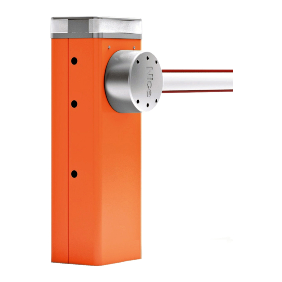
Описание NICE M3BARKIT
Быстродействующая модель для самого интенсивного использования. Выдерживает нагрузку популярных паркингов, терминалов, может работать на скоростных отрезках трасс.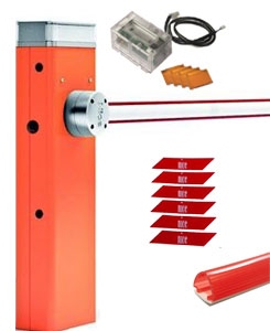
Быстродействующая модель для самого интенсивного использования. Выдерживает нагрузку популярных паркингов, терминалов, может работать на скоростных отрезках трасс.
Стрела шлагбаума имеет овальную форму, и устойчива к порывам ветра. M3BAR оснащен встроенным датчиком индукционной петли. Такая петля позволяет определять наличие в зоне работы системы помехи. При обнаружении препятствия стрела изменяет направление движения. Таким образом достигается повышенный уровень безопасности использования данной модели.
Купить шлагбаум M3BAR стоит для проезда с очень интенсивным потоком автотранспорта, который при этом должен быстро регулироваться, проезд должен иметь хорошую пропускную способность.
Для оперативного выбора оборудования предлагаются 3 варианта готовых систем на основе модели Nice M3Bar.
M3Bar без интегрируемой сигнальной лампы.
M3BARKIT — комплект из тумбы, овальной стрелы 3 м, наклейками и демпфером и интегрируемой сигнальной лампой XBA7. Цена 108495 руб.
M3BARKIT — комплект из тумбы, овальной стрелы 3 м, наклейками и демпфером и интегрируемой сигнальной лампой XBA7. Цена 108495 руб.
M3BARBDKIT1 комплект из тумбы, овальной стрелы с демпфером, светодиодами и наклейками, приемника OXIBD, фотоэлементов EPMB, интергируемой светофорной лампы XBA8. Цена 120045 руб
Двигатель 24 В. Мощность 150 Вт. Оборудование выполняет по 150 маневров открывание — закрывание в час! Время открывания проезда (подъема стрелы) — 1-1,5 сек.
Схема установки шлагбаума Nice M3BAR :
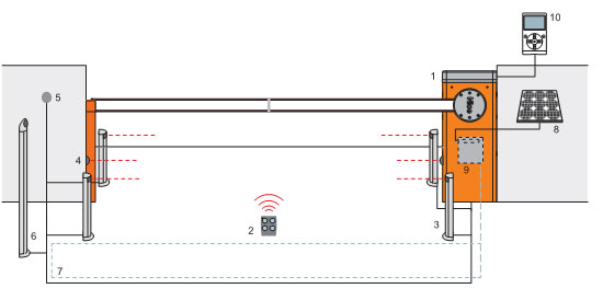
1 — шлагбаум M-Bar
2 — брелок — пульт радиоуправления
3 — фотоэлементы на стойке
4 — фотоэлементы
5 — переключатель цифровой или с ключом
6 — переключатель на стойке
7 — индукционная петля
8 — солнечная панель (при работе с системой Solemyo)
9 — аккумуляторная батарея PSY24 (при работе с системой Solemyo)
10 — специальное устройство O-View, используемое при работе с системами Opera
Габаритные размеры автоматического шлагбаума M3Bar
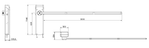
Надежная тумба модели M-Bar может комплектоваться более длинными стрелами для более широких проездов. Выбрать необходимый вариант из модификаций M-Bar можно на соответствующей странице.
Упорядочить по Цене
| Поиск в названии | Поиск в описании | |
|---|---|---|
Came Ati 5000 инструкция
- Инструкции

Комплектующие Alutech
- Инструкции
Came GARD 8000
- Инструкции
Привод для откатных ворот FAAC 740
- Инструкции
SHAFT 30 инструкция
- Инструкции
Сертификат соответствия требованиям ГОСТ 31174 РФ (Алютех-Сибирь)
- Инструкции
Swing 2500 инструкция
- Инструкции
Инструкция AXOVIA 220 B NS
- Инструкции
Монтаж цепного барьера PRIVEE
- Инструкции
BFT PHOBOS инструкция
- Инструкции
ZF1N блок управления Came инструкция
- Инструкции
Проспект гаражные секционные ворота Alutech
- Инструкции
GARD 3750 инструкция
- Инструкции
Инструкция LUX G WINTER
- Инструкции
SHAFT 120 инструкция
- Инструкции
Заключение гос. сан.-эпидем. экспертизы на ворота секционные АЛЮТЕХ
- Инструкции
DoorHan Swing 3000 инструкция
- Инструкции
Инструкция по настройки пульта Somfy KeyGo RTS
- Инструкции
DoorHan Fast 750
- Инструкции
BFT RIGEL5 инструкция
- Инструкции
Came Krono инструкция
- Инструкции
Обслуживание Алютех гаражных ворот
- Инструкции
Came GARD 4000 инструкция
- Инструкции
Nice MC824H инструкция
- Инструкции
Comunello Abacus инструкция
- Инструкции
Сертификат соответствия Алютех Украина
- Инструкции
DoorHan Swing 5000 инструкция
- Инструкции
Боллард гидравлический
- Инструкции
Sectional 1200 инструкция
- Инструкции
Блок управления ALTAIR P инструкция
- Инструкции
Came Ferni 1000 инструкция
- Инструкции
Инструкция по монтажу двери боковой серии SDN
- Инструкции
GARD 6500 инструкция
- Инструкции
Инструкция Nice HOPP
- Инструкции
Nice SO 2000 инструкция
- Инструкции
Сертификат соответствия двери боковой серии SDN
- Инструкции
DoorHan Arm 320 инструкция
- Инструкции
BFT EASY 115 500 инструкция
- Инструкции
DoorHan Sectional 800 PRO
- Инструкции
VIRGO BFT инструкция
- Инструкции
ZM3E блок управления Came инструкция
- Инструкции
Инструкция по монтажу фальшпанели
- Инструкции
Came GARD 4040 инструкция
- Инструкции
Инструкция выдвижного столба механического SCUDO-G
- Инструкции
DEXXO PRO 3S 800/1000 RTS инструкция
- Инструкции
WIDEM шлагбаум
- Инструкции
PCB SW инструкция
- Инструкции
AXI BROWN Came для распашных ворот инструкция
- Инструкции
MICHELANGELO 60 инструкция
- Инструкции
Блок управления BFT ALCOR N инструкция
- Инструкции
BFT ARES BT 1500 инструкция
- Инструкции
Комплектующие серии SG для въездных ворот
- Инструкции
Шлагбаум FAAC 615 инструкция
- Инструкции
Инструкция по настройке блока управления Control Box
- Инструкции
Привод Somfy ELIXO 800 230 B RTS
- Инструкции
Настройка шлагбаума Nice SBAR
- Инструкции
Инструкция Standart Receiver RTS
- Инструкции
Блок управления Came ZL65 инструкция
- Инструкции
Шлагбаум GARD 6000 инструкция
- Инструкции
BFT MOOVI 30S
- Инструкции
BFT ARES 1500 инструкция
- Инструкции
Гаражные секционные ворота Alutech
- Инструкции
FAAC 640 инструкция
- Инструкции
Инструкция DEXXO PRO 3S RTS
- Инструкции
Шлагбаум FAAC 620 инструкция
- Инструкции
Подключение шлагбаума Nice MBAR
- Инструкции
Инструкция Nice CORE — WiFi радиоинтерфейс
- Инструкции
Came Ati 3000 инструкция
- Инструкции
Шлагбаум FAAC 617
- Инструкции
BFT MOOVI 30 инструкция
- Инструкции
Nice SU 2000
- Инструкции
Гаражные ворота Алютех
- Инструкции
FAAC 624 BLD
- Инструкции
Инструкция AXOVIA MultiPro 3S RTS
- Инструкции
FAAC 624 BLD
- Инструкции
BFT IGEA BT инструкция
- Инструкции
Инструкция приложения MyNiceWelcome
- Инструкции
Блок управления Came ZA3N
- Инструкции
PERSEO CBE инструкция
- Инструкции
BFT GIOTTO инструкция
- Инструкции
Nice Spin инструкция
- Инструкции
Гаражные ворота выбор
- Инструкции
FAAC 680 инструкция
- Инструкции
Nice TOONA 4016P инструкция
- Инструкции
STOPPY MBB инструкция
- Инструкции
KUSTOS BT А40 инструкция
- Инструкции
Инструкция Nice AGIO
- Инструкции
Шлагбаум MOOVI 60
- Инструкции
Nice TOO 3000
- Инструкции
Инструкция NIGHT&DAY SPEED
- Инструкции
P7 WINTER инструкция
- Инструкции
SHAFT 60 инструкция
- Инструкции
Преимущества гаражных ворот
- Инструкции
Came ATI 3024 и ATI 5024
- Инструкции
Nice TOONA 5016P инструкция
- Инструкции
Шлагбаум FAAC 620 инструкция
- Инструкции
THALIA BFT инструкция
- Инструкции
Инструкция Nice AIR настенный бесконтактный радиопередатчик
- Инструкции
Программирование пульта FLOR
- Инструкции
Nice A60 инструкция на русском
- Инструкции
DoorHan BARRIER PRO инструкция
- Инструкции
Монтаж цепного барьера DoorHan Chain-Barrier
- Инструкции
Электронная принципиальная схема блока управления SHAFT 60
- Инструкции
Сертификат Алютех соответствия требованиям ГОСТ 31174 РФ до 27.11.2020
- Инструкции
ZL180 блок управления инструкция
- Инструкции
Инструкция IXENGO l 230
- Инструкции
Nice RB 400 инструкция
- Инструкции
IGEA BFT инструкция
- Инструкции
