
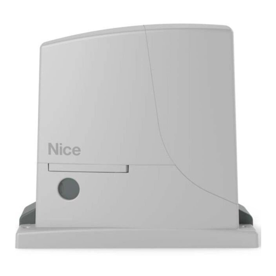
-
Contents
-
Table of Contents
-
Troubleshooting
-
Bookmarks
Quick Links
Nice
ROX600
ROX1000
For sliding gates
EN — Instructions and warnings for installation and use
Related Manuals for Nice ROX600
Summary of Contents for Nice ROX600
-
Page 1
Nice ROX600 ROX1000 For sliding gates EN — Instructions and warnings for installation and use… -
Page 3: Table Of Contents
CONTENTS GENERAL WARNINGS: SAFETY — INSTALLATION — USE 1 — PRODUCT DESCRIPTION AND INTENDED USE 2 — OPERATING LIMITS 3 — INSTALLATION 4 — ELECTRICAL CONNECTIONS 4.1 — Types of electrical cables 4.2 — Electrical cable connections 5 — STARTING THE AUTOMATION AND CHECKING THE CONNECTIONS 5.1 — Hooking the automation up to the mains 5.2 — Learning the devices…
-
Page 4: General Warnings: Safety — Installation — Use
GENERAL WARNINGS: SAFETY — INSTALLATION — USE (instructions translated from Italian) These warnings are copies straight from the Regulations and as far as possible applicable to the product in question. ATTENTION Important safety instructions. Follow all instructions as improper installation may cause serious damage ATTENTION Important safety instructions.
-
Page 5: Product Description And Intended Use
4 ÷ 6 6 ÷ 8 8 ÷ 10 10 ÷ 12 Caution! Any other use or use with dimensions greater than specified is non-conforming. Nice declines all liability for damage and injury resulting for non-conforming use. English – 3…
-
Page 6: Installation
Fig. 1 shows the contents of the package: check that everything is Fig. 2 shows the location of the components of a typical installation present and correct. using Nice accessories: a — ROX gearmotor b — photocells c — posts for photocells…
-
Page 7
Dig the foundation and route the electric cable ducting Secure the two anchors to the foundation plate with one 25 ÷ 35 mm nut above and one below. Tighten the lower nut in such a way that the thread protrudes by 25/35 mm. Now cast the concrete to secure the foundation plate. -
Page 8
d — screw down the adjuster screws so that the gearmotor is at the proper height, leaving a gap of 1-2 mm between the pinion and the rack (this is to prevent the gate loading the gearmotor shaft) e / f / g — release the gearmotor h — open the gate fully by hand 1÷2 mm i — rest the first section of rack on the gearmotor’s pinion:… -
Page 9
m — slide the gate by hand and, using the pinion as a reference, install the other sections of rack 1÷2 mm n — cut any excess rack off the end Slide the gate open and closed by hand to check that the rack is properly aligned with the pinion. N.B.: make sure that there is a gap of 1-2 mm between the rack and pinion for the entire length of the gate 1÷2 mm Tighten the nuts securing the gearmotor to the foundation… -
Page 10
2-3 cm CLOSE: a — slide the gate closed by hand, stopping it 2/3 cm before the mechanical stop b — slide the limit switch bracket along the rack in the close direction until the limit switch trips (you will hear it click) c — after you hear the ‘click’, move the bracket further forwards by 2 cm (minimum) d — secure the bracket to the rack with the provided grub screws 2-3 cm… -
Page 11: Electrical Connections
LIMIT SWITCH 180° MOTOR 180° ELECTRICAL CONNECTIONS CAUTION! — All electrical connections must be carried out with the system disconnected from the mains. Incorrect connections can cause damages to the equipment and injuries to people. Fig. 2 shows the hookup of a typical installation; fig. 7 shows the connections to be made on the control unit. 4.1 — Types of electrical cables Table 3 — Types of electrical cable (see fig.
-
Page 12
AERIAL = AERIAL LIMIT SWITCH = LIMIT SWITCH PROGRAM = MICRO SWITCHES FLASH = FLASH SWITCH BOOST = BOOST RADIO LED = RADIO LED CAPACITOR CAPACITOR = RUN LED PHOTO = LED PHOTO CAPACITOR CAPACITOR LED SBS = LED SBS MOTOR = MOTOR OK LED… -
Page 13: Starting The Automation And Checking The Connections
STARTING THE AUTOMATION AND CHECKING THE CONNECTIONS 5.1 — Hooking the automation up to the mains CAUTION! – The automation must be hooked up to the mains by an expert electrician, in observance of established local regulations. Proceed as follows Manually release the gearmotor so that the gate can be opened and closed Move the gate to the halfway position Manually lock the gearmotor…
-
Page 14: Testing And Commissioning
TESTING AND COMMISSIONING These are the most important phases in automating the gate and ensuring maximum system safety. They must be carried out by qualified and expert personnel that must decide on the tests required to verify the solutions adopted with regard to the risks present and the compliance with laws, directives and regulations;…
-
Page 15: Glossary
PROGRAMMING In this manual the programming procedures are explained with the use of icons and their meanings are given in the following glossary: GLOSSARY Symbol Description Symbol Description led on wait … led off observe / check led flashing press and release the key hold down the key shut off mains power turn on mains power…
-
Page 16: Adjustable Parameters: Trimmer ( Tl — Tp — F )
Factory settings (default) 2 3 4 5 6 7 8 9 10 Micro switches: Semiautomatic (1 = ON) Trimmer TL (Operating Time) Trimmer TP (Pause Time) Trimmer F (Force) CAUTION! — Every time the selection of micro switches 1 and 2 is changed, it is necessary to repeat the device learning procedure as described in paragraph 5.2.
-
Page 17
Table 5 — Programmable functions Switches 1-2 Operation Off-Off Manual (hold-to-run) On-Off Semiautomatic Off-On Automatic (automatic closing) On-On Automatic + Always Closes Switch 3 Operation Condominium (not available in manual mode) Switch 4 Operation Pre-flashing Switch 5 Operation Closes 5 seconds after ‘Photo’ if set to ‘Automatic’ or ‘Close after Photo’ if set to ‘Semiautomatic’… -
Page 18: Integrated Radio Receiver
Switches 9 — 10: Setting a combination of switches 9 and 10, the motor brake procedure is carried out; according to the combination, the intensity of the braking power is established on the basis of the following setup: Table 6 dip9 off …
-
Page 19
7.3.2 — “Remote” memorisation You can memorise a new transmitter without having to operate the receiver key (10-20 m from the receiver). You must have a previously memorised transmitter (old). The new transmitter will be memorised with the same characteristics as the old one. Important! Remote memorisation may be done on all receivers within the range of the transmitter;… -
Page 20
7.3.4 — Locking / Unlocking the radio memory This procedure locks the memory, preventing acquiring and deleting radio transmitters. Table 11 = RADIO key = RADIO led Locking / Unlocking the radio memory Switch the power supply to the control unit off Hold down the RADIO key on the control unit (until step 04) Switch the power back on (continue holding the key down) -
Page 21: Adding Or Removing Devices
FURTHER DETAILS 8.1 — Adding or removing devices Automation devices can be added or removed at any time; in particular at the STOP input, various types of devices can be connected as described in the following paragraphs; WARNING! — at the end of the modifications made to the configuration of the alt input and of the photocell input it is necessary to repeat the device learning procedure as described in paragraph 5.2.
-
Page 22: Power For External Devices
8.2 — Power for external devices To power external devices (transponder badge reader, or backlighting for a keyswitch) connect the device to the control unit as shown in the figure. The power supply voltage is 24V +/- 10% with a maximum available current of 100mA. 8.3 — Oview programmer connection It is possible to connect the Oview programmer to the control unit via the IBT4N interface with a bus cable with 4 electrical wires inside.
-
Page 23: Diagnostics
“Move anyway” function If some safety device is not working or is faulty, it is possible to control and move the gate anyway in “Hold-to-run” mode. For further details, please refer to the tearout insert “USER GUIDE” (final part of the manual). DIAGNOSTICS Some devices are display messages to identify their status and faults.
-
Page 24: Basic Troubleshooting
WHAT TO DO IF… In case of malfunction due to problems during installation of failure of parts, refer to table 13: Table 14 Problem Solution The radio transmitter does not control the Check to see if the transmitter batteries are exhausted, if necessary replace them gate and the led on the transmitter does not light up The radio transmitter does not control the…
-
Page 25: Maintenance
TECHNICAL SPECIFICATIONS All technical specifications stated herein refer to an ambient temperature of 20° C (± 5° C). • Nice S.p.a. reserves the right to apply modifica- tions to products at any time when deemed necessary, maintaining the same intended use and functionality.
-
Page 26: Eu Declaration Of Conformity
Declaration in accordance with the following Directives: 2014/30/EU (EMC); 2006/42/EC (MD) annex II, part B Note: The contents of this declaration correspond to declarations in the official document filed in the offices of Nice S.p.a. and, in particu- lar, the latest version thereof available prior to the printing of this manual. The text herein has been re-edited for editorial purposes. A copy of the original declaration can be requested from Nice S.p.A.
-
Page 27: User Manual (End User Version)
• Your automation system is a machine that will faithful- technician. Nice recommends that maintenance checks ly execute your commands; unreasonable or improper be carried out every six months for normal domestic use,…
-
Page 28
Nice S.p.A. Via Callalta, 1 31046 Oderzo (TV) www.niceforyou.com info@niceforyou.com…
-
Contents
-
Table of Contents
-
Troubleshooting
-
Bookmarks
Quick Links
Nice
ROX600
ROX1000
For sliding gates
EN — Instructions and warnings for installation and use
Related Manuals for Nice ROX600
Summary of Contents for Nice ROX600
- Page 1
Nice ROX600 ROX1000 For sliding gates EN — Instructions and warnings for installation and use… -
Page 3: Table Of Contents
CONTENTS GENERAL WARNINGS: SAFETY — INSTALLATION — USE 1 — PRODUCT DESCRIPTION AND INTENDED USE 2 — OPERATING LIMITS 3 — INSTALLATION 4 — ELECTRICAL CONNECTIONS 4.1 — Types of electrical cables 4.2 — Electrical cable connections 5 — STARTING THE AUTOMATION AND CHECKING THE CONNECTIONS 5.1 — Hooking the automation up to the mains 5.2 — Learning the devices…
-
Page 4: General Warnings: Safety — Installation — Use
GENERAL WARNINGS: SAFETY — INSTALLATION — USE (instructions translated from Italian) These warnings are copies straight from the Regulations and as far as possible applicable to the product in question. ATTENTION Important safety instructions. Follow all instructions as improper installation may cause serious damage ATTENTION Important safety instructions.
-
Page 5: Product Description And Intended Use
4 ÷ 6 6 ÷ 8 8 ÷ 10 10 ÷ 12 Caution! Any other use or use with dimensions greater than specified is non-conforming. Nice declines all liability for damage and injury resulting for non-conforming use. English – 3…
-
Page 6: Installation
Fig. 1 shows the contents of the package: check that everything is Fig. 2 shows the location of the components of a typical installation present and correct. using Nice accessories: a — ROX gearmotor b — photocells c — posts for photocells…
- Page 7
Dig the foundation and route the electric cable ducting Secure the two anchors to the foundation plate with one 25 ÷ 35 mm nut above and one below. Tighten the lower nut in such a way that the thread protrudes by 25/35 mm. Now cast the concrete to secure the foundation plate. - Page 8
d — screw down the adjuster screws so that the gearmotor is at the proper height, leaving a gap of 1-2 mm between the pinion and the rack (this is to prevent the gate loading the gearmotor shaft) e / f / g — release the gearmotor h — open the gate fully by hand 1÷2 mm i — rest the first section of rack on the gearmotor’s pinion:… - Page 9
m — slide the gate by hand and, using the pinion as a reference, install the other sections of rack 1÷2 mm n — cut any excess rack off the end Slide the gate open and closed by hand to check that the rack is properly aligned with the pinion. N.B.: make sure that there is a gap of 1-2 mm between the rack and pinion for the entire length of the gate 1÷2 mm Tighten the nuts securing the gearmotor to the foundation… - Page 10
2-3 cm CLOSE: a — slide the gate closed by hand, stopping it 2/3 cm before the mechanical stop b — slide the limit switch bracket along the rack in the close direction until the limit switch trips (you will hear it click) c — after you hear the ‘click’, move the bracket further forwards by 2 cm (minimum) d — secure the bracket to the rack with the provided grub screws 2-3 cm… -
Page 11: Electrical Connections
LIMIT SWITCH 180° MOTOR 180° ELECTRICAL CONNECTIONS CAUTION! — All electrical connections must be carried out with the system disconnected from the mains. Incorrect connections can cause damages to the equipment and injuries to people. Fig. 2 shows the hookup of a typical installation; fig. 7 shows the connections to be made on the control unit. 4.1 — Types of electrical cables Table 3 — Types of electrical cable (see fig.
- Page 12
AERIAL = AERIAL LIMIT SWITCH = LIMIT SWITCH PROGRAM = MICRO SWITCHES FLASH = FLASH SWITCH BOOST = BOOST RADIO LED = RADIO LED CAPACITOR CAPACITOR = RUN LED PHOTO = LED PHOTO CAPACITOR CAPACITOR LED SBS = LED SBS MOTOR = MOTOR OK LED… -
Page 13: Starting The Automation And Checking The Connections
STARTING THE AUTOMATION AND CHECKING THE CONNECTIONS 5.1 — Hooking the automation up to the mains CAUTION! – The automation must be hooked up to the mains by an expert electrician, in observance of established local regulations. Proceed as follows Manually release the gearmotor so that the gate can be opened and closed Move the gate to the halfway position Manually lock the gearmotor…
-
Page 14: Testing And Commissioning
TESTING AND COMMISSIONING These are the most important phases in automating the gate and ensuring maximum system safety. They must be carried out by qualified and expert personnel that must decide on the tests required to verify the solutions adopted with regard to the risks present and the compliance with laws, directives and regulations;…
-
Page 15: Glossary
PROGRAMMING In this manual the programming procedures are explained with the use of icons and their meanings are given in the following glossary: GLOSSARY Symbol Description Symbol Description led on wait … led off observe / check led flashing press and release the key hold down the key shut off mains power turn on mains power…
-
Page 16: Adjustable Parameters: Trimmer ( Tl — Tp — F )
Factory settings (default) 2 3 4 5 6 7 8 9 10 Micro switches: Semiautomatic (1 = ON) Trimmer TL (Operating Time) Trimmer TP (Pause Time) Trimmer F (Force) CAUTION! — Every time the selection of micro switches 1 and 2 is changed, it is necessary to repeat the device learning procedure as described in paragraph 5.2.
- Page 17
Table 5 — Programmable functions Switches 1-2 Operation Off-Off Manual (hold-to-run) On-Off Semiautomatic Off-On Automatic (automatic closing) On-On Automatic + Always Closes Switch 3 Operation Condominium (not available in manual mode) Switch 4 Operation Pre-flashing Switch 5 Operation Closes 5 seconds after ‘Photo’ if set to ‘Automatic’ or ‘Close after Photo’ if set to ‘Semiautomatic’… -
Page 18: Integrated Radio Receiver
Switches 9 — 10: Setting a combination of switches 9 and 10, the motor brake procedure is carried out; according to the combination, the intensity of the braking power is established on the basis of the following setup: Table 6 dip9 off …
- Page 19
7.3.2 — “Remote” memorisation You can memorise a new transmitter without having to operate the receiver key (10-20 m from the receiver). You must have a previously memorised transmitter (old). The new transmitter will be memorised with the same characteristics as the old one. Important! Remote memorisation may be done on all receivers within the range of the transmitter;… - Page 20
7.3.4 — Locking / Unlocking the radio memory This procedure locks the memory, preventing acquiring and deleting radio transmitters. Table 11 = RADIO key = RADIO led Locking / Unlocking the radio memory Switch the power supply to the control unit off Hold down the RADIO key on the control unit (until step 04) Switch the power back on (continue holding the key down) -
Page 21: Adding Or Removing Devices
FURTHER DETAILS 8.1 — Adding or removing devices Automation devices can be added or removed at any time; in particular at the STOP input, various types of devices can be connected as described in the following paragraphs; WARNING! — at the end of the modifications made to the configuration of the alt input and of the photocell input it is necessary to repeat the device learning procedure as described in paragraph 5.2.
-
Page 22: Power For External Devices
8.2 — Power for external devices To power external devices (transponder badge reader, or backlighting for a keyswitch) connect the device to the control unit as shown in the figure. The power supply voltage is 24V +/- 10% with a maximum available current of 100mA. 8.3 — Oview programmer connection It is possible to connect the Oview programmer to the control unit via the IBT4N interface with a bus cable with 4 electrical wires inside.
-
Page 23: Diagnostics
“Move anyway” function If some safety device is not working or is faulty, it is possible to control and move the gate anyway in “Hold-to-run” mode. For further details, please refer to the tearout insert “USER GUIDE” (final part of the manual). DIAGNOSTICS Some devices are display messages to identify their status and faults.
-
Page 24: Basic Troubleshooting
WHAT TO DO IF… In case of malfunction due to problems during installation of failure of parts, refer to table 13: Table 14 Problem Solution The radio transmitter does not control the Check to see if the transmitter batteries are exhausted, if necessary replace them gate and the led on the transmitter does not light up The radio transmitter does not control the…
-
Page 25: Maintenance
TECHNICAL SPECIFICATIONS All technical specifications stated herein refer to an ambient temperature of 20° C (± 5° C). • Nice S.p.a. reserves the right to apply modifica- tions to products at any time when deemed necessary, maintaining the same intended use and functionality.
-
Page 26: Eu Declaration Of Conformity
Declaration in accordance with the following Directives: 2014/30/EU (EMC); 2006/42/EC (MD) annex II, part B Note: The contents of this declaration correspond to declarations in the official document filed in the offices of Nice S.p.a. and, in particu- lar, the latest version thereof available prior to the printing of this manual. The text herein has been re-edited for editorial purposes. A copy of the original declaration can be requested from Nice S.p.A.
-
Page 27: User Manual (End User Version)
• Your automation system is a machine that will faithful- technician. Nice recommends that maintenance checks ly execute your commands; unreasonable or improper be carried out every six months for normal domestic use,…
- Page 28
Nice S.p.A. Via Callalta, 1 31046 Oderzo (TV) www.niceforyou.com info@niceforyou.com…
Привод NICE ROX600
NICE ROX600 — это автоматический привод серии ROX, предназначенный для автоматизации откатных (сдвижных) ворот общим весом створки до 600 кг. Корпус поддерживает высокий стандарт защиты IP44 от пыли и влаги, тем самым надежно защищая от негативного влияния внешних факторов окружающей среды рабочие элементы. Электродвигатель работает от напряжения 230V. Привод по умолчанию рассчитан на правостороннюю установку, но при необходимости может быть установлен с левой стороны ворот, благодаря дополнительной настройке блока управления. При отключении электричества, благодаря механическому расцепителю можно открывать или закрывать ворота вручную. Привод адаптирован для работы в условиях континентального климата России и обладает широким температурным диапазоном эксплуатации от -20°C до +50°C. В условиях резко континентального и арктического климата (температура до -60°C) необходимо использование дополнительного универсального обогревателя NICE PW1 (совместно с термостатом NICE TW1).
В приводе NICE ROX600 установлен блок управления ROA40 для удобства настройки оборудованный интерфейсом IBT4N для подключения программирующего устройства OVIEW/A (поставляется отдельно). Блок управления поддерживает 2 уровня функций (регулировка скорости и усилия, режим «калитки» — частичного открытия для прохода пешехода, обнаружение препятствий, плавный старт и остановка, фототест — движение только после проверки устройств безопасности). В блок управления встроен 4-х канальный радиоприемник, поддерживающий частоту 433,92 МГц и позволяющий записать пульты NICE с кодировкой FLO, FLOR, O-CODE и SMILO. Каждой кнопке пульта можно назначить определенную функцию, которая соответствует команде блока управления (например: К1-пошаговый режим, К2-открытие для прохода пешеходов, К3-открыть, К-4-закрыть). Память приемника рассчитана на хранение до 150 пультов передатчиков (до 100 в режиме записи всех кнопок). Также плата ROA40 позволяет подключить следующее дополнительное оборудование и аксессуары:
• Сигнальную лампу NICE ELAC
• Переключатель замковый NICE EKS
• Wi-Fi модуль NICE IT4WIFI
• Фотоэлементы безопасности NICE EPM или EPS
Привод для откатных ворот NICE ROX600 оборудован механическим концевым выключателем, который реагирует на перемещение стопоров, прикрепленных на рейке, и вырабатывает команду на остановку ворот.
Основные преимущества этой модели:
• Интегрированный радиоприемник, совместимый с кодировками FLO, FLOR, O-CODE, SMILO (первый записанный пульт определяет используемую систему кодировки)
• Удобство программирования блока управления за счет возможности подключения OVIEW/A
• Индикация возможной неисправности на блоке управления с помощью сигнальной лампы
• Высокопрочный пластиковый корпус (Пыле-влагозащита IP44)
• Вес полотна ворот до 600 кг (возможность установки на ворота длиной до 8 метров)
• Запись до 150 пультов в память радиоприемника
Комплектация по умолчанию:
• Электромеханический привод NICE ROX600 для откатных ворот
• Монтажное основание для бетонирования
• Инструкция на Русском языке
Ограничения в зависимости от длины створки:
|
Длина створки (м)
|
Максимальное число циклов/час |
Максимальное число последовательных циклов |
| До 4 | 40 | 20 |
| 4-6 | 25 | 13 |
| 6-8 | 20 | 10 |
Примечание: цикл — полное открытие ворот и возвращение в закрытое состояние.
Ограничения в зависимости от веса створки:
|
Вес створки (кг)
|
Процентное соотношение циклов |
| До 400 | 100% |
| 400 ÷ 500 | 85% |
| 500 ÷ 600 | 70% |
Примечание: по длине створки определяется максимальное число циклов в час и число последовательно выполняемых циклов; по весу створки определяется степень уменьшения числа циклов и максимально допустимая скорость.
Рекомендуемые типы и размеры электрических кабелей при самостоятельной установке привода и подключению дополнительного оборудования:
|
Подсоединение
|
Тип и размер кабеля |
| Питание привода | 1 кабель: 3 x 1,5 мм² |
| Сигнальная лампа с антенной |
1 кабель: 2 x 0,5 мм² 1 экранированный кабель типа RG58 |
| Фотоэлементы |
1 кабель: 2 x 0,25 мм² (TX) 1 кабель: 4 x 0,25 мм² (RX) |
| Переключатель замковый |
2 кабеля: 2 x 0,5 мм² или 1 кабель: 4 x 0,5 мм² |
Купить привод NICE ROX600 для откатных ворот и выбрать удобный способ доставки Вы можете в нашем интернет-магазине, положив необходимое количество товара в корзину и оформив заказ on-line или же связавшись с отделом продаж по телефону: 8 800 302 22 53.

Расскажем о том, как сделать правильный выбор при самостоятельном подпоре и покупке автоматики для откатных ворот. На что, в первую очередь, следует обратить внимание, для исключения проблем при дальнейшей эксплуатации воротной автоматики.
- Описание
-
Подробности
Привод ROX 600 KLT это хорошо известная модель обновленного привода ROBO 500 (ro 500). Новый привод унаследовал все положительные качества предшественника: надежность, удобство настройки, простота установки и, самое главное, долговечность! Автоматический привод NICE ROX 600 KLT подойдет на все бытовые, домашние, дачные ворота до 600 кг. За тот период, что привод поставляется в Россию – он отлично акклиматизировался и работает даже в суровые русские зимы.
Автоматика ROX 600 KLT обладает всем необходимым функционалом:
- Встроенный блок управления с интегрированным приемником.
- Приемник поддерживает кодировки пультов FLO, FLoR, SMILO
- В комплект уже входит два пульта!
- Память приемника поддерживает до 150 пультов.
- Функция автоматического закрытия
- Надежный, долговечный редуктор
Автоматика NICE на Российском рынке вот уже более 10 лет поставляет и обслуживает привода для различных типов ворот. За это время компания и все привода приспособились к климатическим условиям России и готовы бросить вызов самым тяжелым условиям эксплуатации.
- Характеристики
-
Дополнительная информация
Артикул (SKU) ROX600KLT Вес, КГ. 11.0000 Напряжение питания двигателя 230 В переменного тока Интенсивность использования Малая интенсивность Бренд Nice Частота использования 20 циклов/час Скорость 10.8 м/мин Максимальный вес ворот, кг. 600 кг. Тип концевого выключателя Механический Комплектация Привод Диапазон рабочих температур, °С -20…+55 Максимальная потребляемая мощность, Вт 300 Класс защиты IP44 - Отзывы
- Инструкции
-
Вложения товара
Инструкция Nice ROX600/1000 Скачать (pdf 14.08 MB)
Nice ROX600/1000 Скачать (pdf 12.15 MB)
Похожие товары
-

Привод для откатных ворот R-TECH SL1000
17 700,00 руб. -
DoorHan Sliding-1300 KIT комплект привода для откатных ворот
30 000,00 руб. -
DOORHAN SLIDING-800 привод для откатных ворот
18 800,00 руб. -
Привод для откатных ворот NICE ROX1000KIT
24 500,00 руб. -
DoorHan Sliding-800 KIT комплект привода для откатных ворот
27 900,00 руб.
Код: 38289
В избранное
В сравнение
Функционал: Комплект автоматики для откатных ворот
Единица измерения: шт
Вес: 12,100 кг
Объём: 0,02765 м3
Основной склад: Под заказ
28 900,00 руб Розничная цена
22 253,00 рубОптовая цена
Оставить отзыв
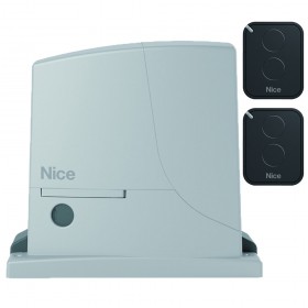
Комплект для откатных ворот со створкой массой до 600 кг. В составе комплекта: привод NICE ROX600 со встроенным блоком управления и интегрированным радиоприемником (1 шт), пульт дистанционного управления NICE FLO2RE (2 шт)
ОСОБЕННОСТИ:
— Простой ввод в эксплуатацию
— Встроенный блок управления с интегрированным радиоприёмником, совместимым с системами кодирования Flo, FloR, Smilo
— Память приёмника на 150 пультов
— Функция автоматического закрытия ворот
ТЕХНИЧЕСКИЕ ХАРАКТЕРИСТИКИ привода:
Масса створки ворот до: 600 кг
Ширина створки ворот до: 6 м
Питание: 230 В
Потребление: 1,4 А
Мощность: 300 Вт
Скорость открывания: 0,18 м/с
Усилие: 600 H
Интенсивность: 20 циклов/час
Класс защиты: IP44
Диапазон рабочих температур: -20…+50° С
Габаритные размеры: 330х210х303 мм
Вес привода: 11 кг
КОМПЛЕКТ ПОСТАВКИ:
Привод откатных ворот ROX600 — 1 шт.
Передатчик 2-х канальный FLO2RE — 2 шт.
Комплект автоматики для откатных ворот NICE ROX600KLT производства компании Nice по цене 28 900,00 RUB (22 253,00 RUB для оптовых поставок) с быстрой доставкой по Москве и в любой город России от интернет-магазина Сатро-Паладин. У нас вы можете прочитать подробное описание, посмотреть технические характеристики и перечень необходимых сопутствующих товаров, найти сертификаты и ознакомиться с реальными отзывами покупателей. Не нашли подходящую модель, отправьте заявку на подбор похожих товаров. Мы производим не только поставку, но и монтаж, разработку проекта и сервисное обслуживание.
Функционал
Комплект автоматики для откатных ворот
Вы можете произвести примерный расчёт доставки на данный товар для розничного магазина (количество принимается равным 1шт.), для более точного расчёта добавьте товар в корзину, расчёт стоимости будет произведён при переходе на страницу корзины. Для клиентов B2B-портала доставка расчитывается менеджером.
- Самовывоз со склада в Москве на Ярославском шоссе
- Курьерская доставка по Москве (только в пределах МКАД)
- Курьерская доставка по Москве (за пределы МКАД)
- Самовывоз из пункта Boxberry (Москва)
- Доставка по России Boxberry
Стоимость доставки: 0 руб.

CLOSE:
a — slide the gate closed by hand, stopping it 2/3 cm before the mechanical stop
b — slide the limit switch bracket along the rack in the close direction until the limit switch trips (you will hear it click)
c — after you hear the ‘click’, move the bracket further forwards by 2 cm (minimum)
d — secure the bracket to the rack with the provided grub screws
2-3 cm
09.
Manually lock the gearmotor
10.
Apply the adhesive label with the unlocking instructions
To install the devices provided in the system, refer to the respective instruction manuals..
IMPORTANT! – The gearmotor is set up (at the factory) for installation on the right (fig. 5); if it must be installed on the left,
proceed as shown in fig. 6 (a — b).
5
8 – English
2-3 cm

ROX
ROX600
ROX1000
ROX1000/V1
For sliding gates
EN - Instructions and warnings for installation and use
CONTENTS
GENERAL WARNINGS
SAFETY - INSTALLATION - USE
2
1 - PRODUCT DESCRIPTION AND INTENDED USE
3
2 - OPERATING LIMITS
3
3 - INSTALLATION
4
4 - ELECTRICAL CONNECTIONS
4.1 - Types of electrical cables
4.2 - Electrical cable connections
9
9
5 - STARTING THE AUTOMATION AND CHECKING
THE CONNECTIONS
5.1 - Hooking the automation up to the mains
10
6 - TESTING AND COMMISSIONING
6.1 - Testing
6.2 - Commissioning
11
12
7 - PROGRAMMING
GLOSSARY
7.1 - Control unit: programming keys
7.1.1 - Trimmer
7.2 - Programmable functions
7.3 - Integrated radio receiver
7.3.1 - Memorisation of radio transmitters
7.3.2 - “Remote” memorisation
7.3.3 - Deleting radio transmitters
12
13
13
14
15
15
16
16
8 - DETAILED INFORMATION
8.1 - Adding or removing devices
8.2 - Power for external devices
8.3 - Total deletion of the receiver’s memory
8.4 - Diagnostics
8.4.1 - Control unit signals
17
17
17
17
17
9 - SCRAPPING
18
10 - BASIC TROUBLESHOOTING...
18
11 - MAINTENANCE
19
12 - TECHNICAL SPECIFICATIONS
19
CE DECLARATION OF CONFORMITY
20
User manual (end user version)
21
English – 1
GENERAL WARNINGS SAFETY - INSTALLATION - USE (instructions translated from Italian)
ATTENTION
ATTENTION
Important safety instructions. Follow all instructions as improper installation may cause serious damage
Important safety instructions. It is important for you to comply with these instructions for your own and other
people’s safety. Keep these instructions
• Before commencing the installation, check the “Technical characteristics” (in this manual), in particular whether this product is suitable for
automating your guided part. If it is not suitable, DO NOT continue with the installation
• The product cannot be used before it has been commissioned as specified in the chapter on “Testing and commissioning”
ATTENTION
According to the most recent European legislation, the implementation of an automation system must comply
with the harmonised standards provided by the Machinery Directive in force, which enables declaration of the
presumed conformity of the automation. Taking this into account, all operations regarding connection to the
electricity grid, as well as product testing, commissioning and maintenance, must be performed exclusively by a
qualified and skilled technician!
• Before proceeding with the installation of the product, check that all the materials are in good working order and suited to the intended applications
• This product is not intended to be used by persons (including children) whose physical, sensory or mental capacities are reduced, or who
lack the necessary experience or skill
• Children must not play with the appliance
• Do not allow children to play with the fixed control devices of the product. Keep the remote controls away from children.
ATTENTION
In order to avoid any danger from inadvertent resetting of the thermal cut-off device, this appliance must not be powered
through an external switching device, such as a timer, or connected to a supply that is regularly powered or switched off by
the circuit
• Provide a disconnection device (not supplied) in the plant’s power supply grid, with a contact opening distance permitting complete disconnection under the conditions dictated by overvoltage category III
• Handle the product with care during installation, taking care to avoid crushing, denting or dropping it, or allowing contact with liquids of any
kind. Keep the product away from sources of heat and naked flames. Failure to observe the above can damage the product, and increase the
risk of danger or malfunction. Should this happen, stop installation immediately and contact Customer Service
• The manufacturer assumes no liability for damage to property, items or persons resulting from non-compliance with the assembly instructions.
In such cases the warranty for material defects is excluded
• The weighted sound pressure level of the emission A is lower than 70 dB(A)
• Cleaning and maintenance to be carried out by the user must not be carried out by unsupervised children
• Before working on the system (maintenance, cleaning), always disconnect the product from the mains power supply
• Check the system periodically, in particular all cables, springs and supports to detect possible imbalances, signs of wear or damage. Do not
use if repairs or adjustments are necessary, since installation failure or an incorrectly balanced door may cause injury
• The packing materials of the product must be disposed of in compliance with local regulations
• When operating a biased-off switch, make sure that other persons are kept away
• When operating the gate, keep an eye on the automated mechanism and keep all bystanders at a safe distance until the movement has been
completed
• Do not operate the product if anyone is working nearby; disconnect its power supply before permitting such work to be done
• If the power cable is damaged, it must be replaced by the manufacturer or by an appointed servicing company or similarly qualified person
in order to prevent any form of risk
INSTALLATION WARNINGS
• Prior to installing the drive motor, check that all mechanical components are in good working order and properly balanced, and that the gate
moves correctly
• If the gate or door being automated has a pedestrian gate, then the system must include a control device that will inhibit the operation of the
motor when the pedestrian gate is open
• Make sure that the control devices are kept far from moving parts but nonetheless in a visible position. Unless a selector is used, the control
devices must be installed at a height of at least 1.5 m and must not be accessible
• That windows, having a gap exceeding 200 mm when open, are to be closed using a biased-off switch if the opening movement is controlled
by a fire-sensing system
• Ensure that entrapment between the driven part and the surrounding fixed parts due to the opening movement of the driven part is avoided
• Permanently fix the label concerning the manual release adjacent to its actuating member
• After installing the drive motor, make sure that the mechanism, protective system and all manual manoeuvres operate properly
2 – English
1
PRODUCT DESCRIPTION AND INTENDED USE
ROX is an electromechanical gearmotor intended for automating residential sliding gates: it is equipped with an electronic control unit with integral radio receiver (433.92 MHz with FLO, FLOR, OPERA, HCS SMILO, etc. coding)
CAUTION! – All uses other than the intended use described and use in environmental conditions other than those described in
this manual should be considered improper and forbidden!
2
APPLICATION LIMITS
Table 1: limits of application in everyday use.
Table 2: limits of application relating to the gate’s size and weight.
The effective suitability of ROX to automate a particular sliding gate depends on the friction as well as other correlated factors, such as ice, that
could interfere with the movement of the gate.
Measure the force required to move the gate through its entire stroke and check that this does not exceed 25% of the ‘maximum force’ (chapter
12 - technical specifications): this leaves a suitable margin for unfavourable climatic conditions which can increase friction.
Table 1 – Application limits
ROX600
ROX1000
ROX1000/V1
Type of limit switch
electromechanical
electromechanical
electromechanical
Optimal width of gate section
(recommended)
5m
5m
5m
Max. gate weight
600 kg
1000 kg
1000 kg
Peak thrust
18 Nm
24 Nm
24 Nm
Corresponding to maximum force 600 N
800 N
800 N
Table 2 – Application limits
ROX600
ROX1000
ROX1000/V1
Leave width (m)
Max. no. of
cycles/hour
Max. no. of
consecutive
cycles
Max. no. of
cycles/hour
Max. no. of
consecutive
cycles
Max. no. of
cycles/hour
Max. no. of
consecutive
cycles
Up to 4
40
20
40
20
60
30
4÷6
25
13
25
13
30
15
6÷8
20
10
20
10
24
12
8 ÷ 10
-
-
-
-
16
8
10 ÷ 12
-
-
-
-
-
-
Caution! Any other use or use with dimensions greater than specified is non-conforming. Nice declines all liability for damage
and injury resulting for non-conforming use.
English – 3
3
INSTALLATION
Important! Before installing the product, refer to chapters 2 and 12 (technical specifications).
Fig. 1 shows the contents of the package: check that everything is
present and correct.
a
b
c
d
e
f
1
2
Fig. 2 shows the location of the components of a typical installation
using Nice accessories:
E
F
- ROX gearmotor
- photocells
- posts for photocells
- Key switch / digital keypad
- flasher
- rack
D
D
C D
B
e
d
b
c
c
a
f
D
A
Before installing the system, check the gearmotor’s clearance (fig. 3) and installation dimensions (fig. 4):
92 mm
303 mm
3
330 mm
210 mm
4
0 ÷ 10
mm
0 ÷ 10
mm
192 mm
192 mm
330 mm
4 – English
0 ÷ 50 mm
0 ÷ 50 mm
330 mm
01.
Dig the foundation and route the electric cable ducting
02.
Secure the two anchors to the foundation plate with one
nut above and one below.
25 ÷ 35 mm
Tighten the lower nut in such a way that the
thread protrudes by 25/35 mm.
03.
Now cast the concrete to secure the foundation plate.
Before the concrete hardens, make sure the
foundation plate is perfectly level and parallel to the
gate.
04.
Allow the concrete to harden.
05.
Secure the gearmotor:
a - Remove the top anchor nuts
b - rest the gearmotor on the anchor dowels: make sure
that it is parallel with the gate section
c - fit the provided washers and nuts and hand tighten
them
English – 5
d - screw down the adjuster screws so that the gearmotor
is at the proper height, leaving a gap of 1-2 mm between
the pinion and the rack (this is to prevent the gate loading
the gearmotor shaft)
g
e / f / g - release the gearmotor
h - open the gate fully by hand
h
h
1÷2 mm
i - rest the first section of rack on the gearmotor’s pinion:
make sure that it corresponds to the start of the gate section and that there is a gap of 1-2 mm between the rack
and the pinion itself (this is to prevent the gate loading the
gearmotor shaft
h
g
l - secure the rack section
1÷2 mm
6 – English
m - slide the gate by hand and, using the pinion as a reference, install the other sections of rack
h
1÷2 mm
n - cut any excess rack off the end
06.
Slide the gate open and closed by hand to check that the rack is properly aligned with the pinion.
N.B.: make sure that there is a gap of 1-2 mm between the rack and pinion for the entire length of the gate
1÷2 mm
07.
Tighten the nuts securing the gearmotor to the foundation
plate fully down and cover the nuts with their caps
1÷2 mm
08.
Install the OPEN and CLOSE limit switch brackets: proceed in the same way for each limit switch
OPEN:
a - slide the gate open by hand, stopping it 2/3 cm before the mechanical stop
b - slide the limit switch bracket along the rack in the open direction until the limit switch trips (you will hear it click)
c - after you hear the ‘click’, move the bracket further forwards by 2 cm (minimum)
d - secure the bracket to the rack with the provided grub screws
English – 7
+2
cm
!
ck
cli
2-3 cm
CLOSE:
a - slide the gate closed by hand, stopping it 2/3 cm before the mechanical stop
b - slide the limit switch bracket along the rack in the close direction until the limit switch trips (you will hear it click)
c - after you hear the ‘click’, move the bracket further forwards by 2 cm (minimum)
d - secure the bracket to the rack with the provided grub screws
+2
2-3 cm
cm
clic
k!
09.
Manually lock the gearmotor
Manually lock the gearmotor.
IMPORTANT! – The gearmotor is set up (at the factory) for installation on the right (fig. 5); if it must be installed on the left, proceed as shown in fig. 6 (a - b).
5
6
8 – English
a
LIMIT SWITCH
b
MOTOR
180°
180°
4
ELECTRICAL CONNECTIONS
CAUTION! - All electrical connections must be made with the system powered off Incorrect connections can result in damage
and injury.
Fig. 2 shows the hookup of a typical installation; fig. 7 shows the connections to be made on the control unit.
4.1 - Types of electrical cables
Table 3 - Types of electrical cable (see fig. 2)
Connection
Type of cable
Maximum length
A
POWER
3 x 1,5 mm
B
C
FLASHER WITH AERIAL
1 cable: 2 x 1,5 mm
1 shielded RG58 cable
10 m
10 m (< 5 m recommended)
D
PHOTOCELLS
1 cable: 2 x 0,25 mm2 (TX)
1 cable: 4 x 0,25 mm2 (RX)
30 m
30 m
E-F
KEY SWITCH
1 cable: 2 x 0,5 mm2 **
20 m
30 m *
2
2
* A power supply cable longer than 30 m may be used provided it has a larger gauge, e.g. 3x2.5mm2, and that a safety grounding system is
provided near the automation unit.
** The two 2 x 0.5 mm2 cables can be replaced by a single 4 x 0.5 mm2 cable.
4.2 - Electrical cable connections: fig. 7
Table 4 - Description of electrical connections
Terminals
Function
Description
1-2
Aerial
- radio receiver aerial input
- aerial integrated into flasher; an external aerial can be used if desired
9 - 12
Step-by-step
input for devices which control movement. NO (Normally Open) contacts can be connected
9 - 10
Stop
- input for devices which lock or stop a movement: NC (Normally Closed) contacts may be connected
- for further details, refer to par. 8.1
9 - 11
Photo
- input for safety devices which when tripped reverse the gate's direction of movement: NC (Normally Closed)
contacts may be used
- for further details, refer to par. 8.1.
5-4
Flashing light
- flasher output (230 V auto-intermittent)
- flashes at regular intervals while the gate is moving: 0.5s on, 0.5s off
Warnings
• NC (Normally Closed) input: these must be shorted if not used; if more than one contact is to be connected to the stop input, they must be
connected IN SERIES;
• NO (Normally Open) input: these must be left unconnected if not used; if more than one contact is to be connected to the input, they must
be connected IN PARALLEL.
• Contacts must be mechanical and disconnected from any voltage.
Sensitive
edges
No specific input; use Nice equipment:
- fixed sensitive edges: use the TCE interface
- mobile sensitive edges: use the FT210 unit or IRW interface
Refer to the product’s instruction manual for details
To make the electrical hookup, proceed as described below with reference to fig. 7:
01.
Open the cover: undo the screw and raise the cover
02.
Run the power cable through the hole (leave 20/30 cm of free cable) and connect it to its terminal clamp
03.
Run the cables of the equipment to be installed or already present through the provided hole (leave 20/30 cm of free cable) and connect
them to their terminal clamps (see fig. 14)
04.
Before closing the cover, program the system: chapter 7
05.
Close the cover and tighten down its bolt
English – 9
7
AERIAL
= AERIAL
LIMIT SWITCH
=
LIMIT SWITCH
PROGRAM
SWITCH
= MICRO SWITCHES
FLASH
=
FLASHER
LED RADIO
= RADIO LED
BOOST
CAPACITOR
=
STARTCONDENSATOR
LED PHOTO
= PHOTOCELL LEDS
RUN
CAPACITOR
=
CAPACITOR RUN
LED P.P.
= STEP-BY-STEP LED
MOTOR
=
MOTOR
LED OK
= OK LED
FUSE
=
FUSE
RADIO
= RADIO KEY
TX
1 2
RX
1 2 3 4 5
FLASH
230 V
NC NO
C C
NO NC
PROGRAM SWITCH
1 2 3 4 5 6 7 8 910
LED
LED
8 9 10 11 12
2 1
LED FCC
LED FCA
4 5
LED:
1 2
(ROX1000)
5
STARTING THE AUTOMATION AND CHECKING THE CONNECTIONS
5.1 - Hooking the automation up to the mains
CAUTION! – The automation must be hooked up to the mains by an expert electrician, in observance of established local
regulations.
Proceed as follows
01.
Manually release the gearmotor so that the gate can be opened and closed
02.
Move the gate to the halfway position
10 – English
03.
Manually lock the gearmotor
04.
Power the automation up and check:
- that the OK led is flashing regularly: 1 flash
per second
- that the gate does not move and that the
flasher is off
ON
if any of these conditions are not satisfied, proceed as follows (step 05)
05.
6
Shut off mains power to the automation and check the electrical connections, photocell alignment, and fuses. If necessary, check the
limit switch connections: move the limit switch levers and check that the switch trips and turns off the FCA / FCC led on the control
unit respectively
TESTING AND COMMISSIONING
These are the most important phases of automation set-up to ensure maximum system safety.
They must be done by a qualified technician who agrees to run the tests and check the solutions to any risks present, as well as checking compliance with regulations, standards and the law: in particular, the requirements of EN 13241-1, EN 12445 and EN 12453.
Any supplementary equipment must be tested separately for operation and interaction with the ROX: refer to the respective user manuals.
6.1 - Testing
The testing procedure can also be performed as a periodic check of the automation devices. Each component of the system (sensitive edges,
photocells, emergency stop, etc.) requires a specific testing phase. To do so, follow the procedures given in the instruction manuals.
Run the test as follows:
01.
Ensure that all specifications in chapter 1 “WARNINGS” have been observed in full
02.
Check that the gate can be moved by hand in both directions with a force no greater than the value given in the application limits (Table 1)
03.
Lock the gearmotor
English – 11
04.
Using the key switch, control key or radio transmitter, test the opening and closing of the gate and make sure that it moves in the intended direction
05.
The test should be carried out a number of times to make sure that the gate moves smoothly, that there are no points of excessive
friction and that there are no defects in the assembly or adjustments
06.
Check the operation of the safety equipment, one by one (photocells, sensitive edges, etc.)
07.
Check the operation of the photocells and any interference with other equipment:
1 - pass a dia. 5 cm length 30 cm cylinder along the optical axis, first close to the TX, then close to the RX
2 - check that the photocells trip in any condition, switching from active to alarm and back
3 - check that tripping the photocell results in the intended response of the control unit: e.g., when tripped during a closing stroke, the
gate changes direction.
08.
If the dangerous situations caused by the movement of the door have been safeguarded by limiting the force impact, the user must
measure the impact force according to the EN 12445 standard.
If the adjustment of the “force” is used to assist the system for the reduction of the impact force, try to find the adjustment that gives
the best results.
6.2 - Commissioning
Commissioning can take place only after all testing phases have been terminated successfully (par. 6.1).
Partial or “makeshift” commissioning is strictly prohibited.
01.
Prepare and store the technical documentation for the automation for at least 10 years. This must include at least: an assembly drawing
of the automation, a wiring diagram, an analysis of hazards and solutions adopted, a manufacturer’s declaration of conformity of all
the devices installed (for ROX use the annexed CE declaration of conformity); a copy of the automation system instruction manual and
maintenance schedule.
02.
Affix a label or plate permanently to the gate, bearing instructions on how to manually release the gearmotor: use the figures included
at the end of the User Manual (tearout insert)
03.
Post a permanent label or sign near the gate containing this
picture (min. height 60 mm):
04.
Using the key switch or radio transmitter, test the opening and closing of the gate and make sure that it moves in the intended direction
05.
Prepare the declaration of conformity of the automation system and deliver it to the owner.
06.
Give the owner the user manual (tearout insert)
07.
Prepare and give the owner the maintenance schedule
08.
The force adjustment is an important safety aspect and must be done with care by an expert technician. Important! - Adjust the force
to enable the gate to move as intended; higher forces than this can cause injury to animals and persons or damage to property if the
gate collides with an obstacle.
09.
Before commissioning the gate, inform the owner in writing about the attendant residual risks.
7
PROGRAMMING
In this manual the programming procedures are explained with the use of icons and their meanings are given in the following glossary:
GLOSSARY
Symbol
Description
Symbol
Description
RADIO led on
wait ...
RADIO led off
observe / check
RADIO led flashing
press and release the RADIO key
shut off mains power
hold down RADIO key
turn on mains power
release RADIO key
OFF
ON
12 – English
press and release the desired key on the radio
transmitter to be memorized
↕
release the RADIO key exactly when the led behaves
in the specified manner (on, flashing, off)
hold down the desired key on the radio transmitter
to be memorized
correct procedure
release the transmitter key
INCORRECT procedure
7.1 - Control unit: programming keys
The control unit has a variety of factory settings which can be reprogrammed: this chapter describes the available functions and how to program
them.
The control unit is equipped with microswitches and trimmers (fig.7):
Name
Symbol
Description
PROGRAM SWITCH
Activates a function
Trimmer TL
Sets the Operating Time parameters (see paragraph 7.1.1)
Trimmer TP
Sets the Pause Time parameters’ (see paragraph 7.1.1)
Trimmer F
Sets the Force parameters (see paragraph 7.1.1)
RADIO key
Programs the radio receiver
Factory settings (default)
MICRO SWITCHES:
ON
OFF
Semiautomatic (1 = ON)
Trimmer TL (Operating Time)
1 2 3 4 5 6 7 8 9 10
Trimmer TP (Pause Time)
Trimmer F (Force)
7.1.1 - Trimmer (TL - TP - F)
The control unit’s parameters can be adjusted with three trimmers (fig. 7)
TL (Operating Time)
Operating mode
Adjustment
sets the maximum duration of an 01. select ‘Semiautomatic’ or ‘Automatic’ and set micro switch 1 to ‘ON’
Open or Close movement
02. set trimmer TL to the mid position
03. run a full Open and Close cycle:
check that the maximum duration setting (Open / Close) is high enough and that a margin of 2 or 3
seconds remains.
Adjust trimmer TL to its maximum setting if necessary.
N.B.: if this time is not sufficient, cut the TLM jumper next to trimmer TL (fig. 7) to obtain a ‘Long
Operating Time’ (TLM)
Slow down function: to use this function, activate the programmable function “slow down” and set trimmer TL so that the slow down phase
starts 50/70 cm before the gate trips the limit switch.
N.B.: the result of an adjustment to this parameter is visible during the first Open movement run after the modification has been made.
English – 13
TP (Pause Time)
Operating mode
Adjustment
sets the time between the end of 01. select ‘Automatic’ and set micro switch 2 to ‘ON’
an Open movement and the start 02. set trimmer TP to the desired value;
of the next Close movement
03. to check the time setting, run a full Open movements and see how long it takes before the Close
movement starts.
F (Force)
CAUTION! – Adjustments to this parameter are safety critical: take great care when making this adjustment.
To adjust the parameter, try various settings: you must measure the force applied by the gate when moving and compare it with local regulations.
7.2 - Programmable functions
The control unit has a set of micro switches (PROGRAM SWITCH - fig. 7) which activate functions to adapt the automation to the user’s needs
as well as making it safer to use.
The micro switches select the operating modes and program the functions, as described in Table 5.
To activate/deactivate a function:
Micro switches (1 ... 10)
ACTIVATE
DEACTIVATE
ON
OFF
IMPORTANT! - some functions are safety critical; make sure to check which function is safest.
Table 5
Switches 1-2
Operation
Off-Off
Manual (hold-to-run)
On-Off
Semiautomatic
Off-On
Automatic (automatic closing)
On-On
Automatic + Always Closes
Switch 3
Operation
On
Condominium (not available in manual mode)
Switch 4
Operation
On
Pre-flashing
Switch 5
Operation
On
Closes 5 seconds after ‘Photo’ if set to ‘Automatic’ or ‘Close after Photo’ if set to ‘Semiautomatic’
Switch 6
Operation
On
Safety “Photo” also when Opening
Switch 7
Operation
On
Gradual Start-up
Switch 8
Operation
On
Slow down
Switch 9
Operation
On
Brake
Switch 10
Operation
Off
Not used
Switches 1-2:
Manual operation
the movement is only executed while the control is active (transmitter key held to run).
Semiautomatic
operation
sending a command executes the entire movement until the operating time expires or the gate trips the limit switch.
Automatic
operation
after an Open, the system pauses and then automatically Closes the gate.
Always Closes
operation
follows a power failure: if, when power is restored, the control unit determines that the gate is open, it automatically
flashes the flasher for five seconds and then runs a Close cycle.
Switch 3:
Condominium
function
when a “Step-by-Step” command is sent and the gate starts to Open, it cannot be stopped by any other “Step-byStep” or Open command sent by radio until it has completed.
When closing, on the other hand, sending a new Step-by-Step command will stop and reverse the movement.
Switch 4:
When a command is sent, the flasher starts flashing and, after 5 seconds (2 seconds in Manual mode), the movement starts.
14 – English
Switch 5:
This function, when set in Automatic mode, holds the gate open only for the time required for vehicles or pedestrians to pass through it; when
the Photo device is cleared, the movement stops and a Close movement starts after a 5 second delay.
If the functions is set in Semiautomatic mode, when the photocells are tripped while the gate is closing, automatic Close is activated with the
programmed Pause Time.
Switch 6:
The Foto function is usually active only during Close movements; if micro switch 6 is set to “ON”, tripping the photocell interrupts Open
movements too. On the other hand, in Semiautomatic or Automatic modes, the Open movement starts again as soon as the photocell
clears.
Switch 7
This function activates a soft start to gate movements to prevent them moving jerkily.
Switch 8:
Slow down, which reduces the speed to 30% of its nominal value, reduces the impact force of the gate at the end of a movement.
When this function is active, yo must adjust the operating Time (TL) since the start of the slow down phase is linked to this setting. Set the
TL so that the slow down starts 50-70 cm before the limit switch is tripped. The slow down function not only reduces the speed of the gate
but also the torque exerted by the motor ( by 70%). CAUTION – In automations which demand a high motor torque, setting this function can
stop the motor.
Switch 9:
This function brakes the motor at the end of a movement; the effect is moderate at first, but increases to quickly and smoothly stop the
gate.
Switch 10:
Not used.
7.3 - Integrated radio receiver
For remote control operation, the control unit has an integral radio receiver (433.92 MHz compatible with FLO, FLOR, OPERA, and HCS SMILO
coding)
Since the coding systems are different, the first transmitter to be memorised determines the type of transmitter memorised thereafter.
• To modify the coding family, proceed as indicated in ‘Total deletion of the receiver’s memory’ - par. 8.3.
• To check whether the receiver has already memorised any transmitters, and to determine the type of coding, proceed as follows:
OFF
01.
Table 7
to control unit
ON
02.
03.
to control unit
count the number of green flashes emitted by the receiver and
refer to table 7
Flash
Coding
1
Flo
2
O-Code / FloR / TTS
3
Smilo
4
no transmitter memorised
7.3.1 - Memorisation of radio transmitters
Each radio transmitter is recognised by the radio receiver by means of a “code” which is different from that of any other transmitter.
There are two types of memorisation: Mode 1 and Mode 2.
• Mode 1:
Table 8
automatically assigns the commands indicated in table 8 to the
transmitter’s keys.
Transmitter key
Command
Each transmitter is memorised in a single step, with all keys pro1
Step-by-step
grammed: it does not matter which key is pressed. (One memory location is occupied for each key).
2
STOP
N.B.: when memorised in Mode 1, a transmitter can control only one
3
Open
automation.
4
Close
N.B.: single-channel transmitters have only key 1; two-channel
transmitters have keys 1 and 2
Mode 1 memorisation
01.
02.
x 4s
RADIO KEY
03.
↕
RADIO KEY AND LED
04.
within 10s
x 3s
TRANSMITTER DESIRED BUTTON
RADIO LED
English – 15
• Mode 2:
freely assigns a command among those listed in table 9.
For each phase, only one key is memorised (the one pressed during
memorisation).
(One memory location is occupied for each key).
Table 9
Transmitter key
Command
1
Step-by-step
2
STOP
3
Open
4
Close
Mode 2 memorisation
01.
02.
03.
04.
Step-bystep
x 1
within 10s
x 3s
STOP
x 2
within 10s
x 3s
Open
x 3
within 10s
x 3s
Close
x 4
within 10s
x 3s
RADIO KEY
KEY IN QUESTION
TRANSMITTER
RADIO LED
RADIO LED
N.B.: if you wish to memorise other transmitters, repeat step 03 within 10 sec. The memorisation procedure terminates after 10 sec if no other operations
are run
7.3.2 - “Remote” memorisation
You can memorise a new transmitter without having to operate the receiver key (10-20 m from the receiver).
You must have a previously memorised transmitter (old). The new transmitter will be memorised with the same characteristics as the old one.
Important! Remote memorisation may be done on all receivers within the range of the transmitter; therefore, only the one involved in the operation should be kept switched on.
Standard procedure
Alternative procedure
During the procedure, if the old transmitter was memorised in:
During the procedure, if the old transmitter was memorised in:
- Mode 1 ¨ press any key
- Mode 2 ¨ press the key you wish to memorise
- Mode 1 ¨ press any key
- Mode 2 ¨ press the key you wish to memorise
01.
With the motor stopped, stand close to the control unit
01. With the motor stopped, stand close to the control unit
02.
NEW
transmitter
03.
OLD
transmitter
already
memorised
04.
NEW
transmitter
*
x 1s
*
NEW
transmitter
*
OLD previously
03. memorised
transmitter
**
NEW
transmitter
*
OLD previously
05. memorised
transmitter
**
02.
x 5s
x 1s
x 1s
04.
x 1s
If the procedure terminated successfully the new transmitter is memorised
* same key as NEW transmitter
x 3s
x 3s
x 3s
RADIO LED
x 3s
not visible
remote
If the procedure terminated successfully the new transmitter is
memorised
* same key as NEW transmitter
** same key as OLD transmitter
Deleting radio transmitters
01.
02.
03.
04.
↕
RADIO KEY
16 – English
RADIO LED
RADIO LED
RADIO KEY AND LED
RADIO KEY AND LED
8
STOP
FURTHER DETAILS
8.1 - Adding or removing devices
You can add or remove devices at any timee.
8 9 10 11 12
STOP input
Input that stops movement immediately, followed by a brief reverse of the manoeuvre.
You may connect devices with NC contacts to this input; multiple devices can be connected in series.
N.B.: when the NC contact opens, the automation stops and reverses its direction briefly.
8 9 10 11 12
8 9 10 11 12
8 9 10 11 12
STOP
TX
1 2
8 9 10 11 12
Photocells
RX
1 2 3 4 5
8 9 10 11 12
To add a pair of photocells, proceed as follows:
01. Power up the receivers (RX) via terminals 8 - 9
02. Connect the receiver’s NC contact in series with the NC contact already connected to control unit terminals 9 - 11.
TX
1 2 3 4 5
8 9 10 11 12
8 9 10 11 12
8 9 10 11 12
1 2
RX
8 9 10 11 12
8 9 10 11 12
If using two pairs of photocells, to prevent them interfering with each other, activate the synchronisation function described in the respective
user manual.
9 10 11 12
8 9 10 11 12
To power external devices (transponder badge reader, or backlighting for a keyswitch) connect the device
to the control unit as shown in the figure.
The power supply voltage is 24Vac -20% ÷ +30% with a maximum available current of 100mA.
24 Vac (30 Vac max)
8
8.2 - Power for external devices
0
8.3 - Total deletion of the receiver’s memory
To cancel all memorised transmitters or all data in the receiver’s memory, proceed as follows:
01.
02.
03.
04.
↕
RADIO KEY
RADIO LED
RADIO LED
RADIO KEY AND LED
RADIO KEY AND LED
8.4 - Diagnostics
Some devices are display messages to identify their status and faults.
8.4.1 - Control unit signals
The leds on the control unit issue signals to indicate their normal/faulty operation.
Table 10 lists the signals:
English – 17
Table 10
OK LED
Cause
Solution
Off
Malfunction
Make sure there is power supply; check to see if the fuses are blown; if necessary,
identify the reason for the failure and then replace them with others of the same type
On
Serious
malfunction
There is a serious malfunction; try switching off the control unit for a few seconds; if the
condition persists, it means there is a malfunction and the circuit board has to be replaced
One flash every All OK
second
Normal operation of control unit
2 quick flashes
The status of the inputs has This is normal when there is a change in one of the inputs: Step-by-Step, STOP, triggerchanged
ing of photocells or the radio transmitter is used
PHOTO led
Cause
Solution
Off
Photocell input activated
At the start of the manoeuvre, one or more photocells are preventing movement; check
to see if there are any obstacles, also check the NC connection for faults.
On
All OK
The photocell is aligned and the movement is permitted
FCA and FCC
leds
Cause
Solution
Off
Activation of the STOP input
Check the devices connected to the STOP input
On
All OK
STOP Input active
9
DISPOSAL OF THE PRODUCT
This product constitutes an integral part of the automation system, therefore it must be disposed of together with the former.
As in installation, also at the end of product lifetime, the disassembly and scrapping operations must be performed by qualified personnel.
This product is made up of different types of material, some of which can be recycled while others must be disposed of. Seek information on the
recycling and disposal systems envisaged by the local regulations in your area for this product category.
CAUTION! – Some parts of the product may contain polluting or hazardous substances which, if disposed of into the environment, constitute serious environmental and health risks.
As indicated by the symbol, the product may not be disposed of as domestic waste. Sort the materials for disposal, according
to the methods envisaged by current legislation in your area, or return the product to the retailer when purchasing an equivalent
product.
CAUTION! - Local legislation may include the application of serious fines in the event of improper disposal of this
product.
10
WHAT TO DO IF...
In case of malfunction due to problems during installation of failure of parts, refer to table 11:
Table 11
Problem
Solution
The radio transmitter does not control the Check to see if the transmitter batteries are exhausted, if necessary replace them
gate and the led on the transmitter does not
light up
The radio transmitter does not control the Check to see if the transmitter has been memorised correctly in the radio receiver.
gate but the led on the transmitter lights up Check that the emission of the transmitter radio signal is correct by means of this empirical test:
push a key and rest the LED on the aerial of a normal radio (ideally an economical one) that
is switched on and tuned in, as close as possible, to 108.5Mhz FM; a slight crackling sound
should be heard
No manoeuvre starts and the OK LED fails Check that the product is being supplied 230 V mains power
to flash.
Check to see if fuses F1 and F2 (fig. 7) have blown; if necessary, identify the reason for the
failure and then replace the fuses with others that have the same current rating and specs
No manoeuvre starts and the flasher is off
18 – English
Check that the command is actually received: if the command reaches the Step-by-Step input,
the OK led flashes twice to indicate that the command has been received
11
MAINTENANCE
To keep the system safe and ensure a long service life, it must be serviced regularly: at most every 6 months or after 20,000 movements since
the last service.
CAUTION! – The maintenance operations must be performed in strict compliance with the safety directions provided in this
manual and according to applicable legislation and standards.
01.
02.
OFF
Check the wear and tear on the moving parts: pinion, rack and the gate components; if necessary replace them.
03.
12
Check for any deterioration in automation system components, paying special attention to erosion or oxidation of
the structural parts. Replace any parts which are below the required standard.
ON
Run all the tests and checks indicated in par. 6.1 - Testing.
TECHNICAL SPECIFICATIONS
All technical specifications stated herein refer to an ambient temperature of 20° C (± 5° C). • Nice S.p.a. reserves the right to apply modifications to products at any time when deemed necessary, maintaining the same intended use and functionality.
ROX600
Type
ROX1000
ROX1000/V1
Electromechanical gear motor for the automatic movement of sliding gates for residential use, complete
with electronic control unit
Pinion Z
15; Modulus: 4; Pitch: 12.5 mm; Primitive diameter: 60 mm
Peak thrust
18 Nm
24 Nm
24 Nm
Nominal torque
9 Nm
9 Nm
12 Nm
Speed (no load)
11 m/min
11 m/min
13 m/min
Nominal torque speed
8.5 m/min
8.5 m/min
8.5 m/min
Operating cycles
20 cycles/hour
20 cycles/hour
25 cycles/hour
Maximum continuous operating
time
4 minutes
Nominal power supply
230 V - 50/60 Hz
230 V - 50/60 Hz
120 V - 60 Hz
Nominal power
300 W
350 W
350 W
Electrical isolation class
Flasher output
STOP input
Step-by-step Input
PHOTO input
Radio AERIAL Input
Radio receiver
Operating temperature
Protection class
1 (a safety grounding system is required)
For 1 flashing light 230 V auto-intermittent
For NC contacts (a variation with respect to the closed state causes the command “STOP”).
For NO contacts (closing of the contact causes the “STEP-BY-STEP” command)
For NC contacts (a variation with respect to the closed state causes a change of direction during closing
when the photocell is occluded)
52 Ω for RG58 or similar type of cable
Incorporated
-20°C - 50°C
IP 44
Dimensions (mm) and weight
330 x 210 x 303 h; 11 kg
Dimensioni (mm) e peso
330 x 210 x 303 h; 11 kg
Integrated radio receiver
Type
Frequency
4 channel receiver for incorporated radio command
433.92MHz
Transmitter compatibility
FLO, FLOR, OPERA, HCS SMILO... coding
Transmitters memorized
Up to 1024 if memorized in mode 1
Input impedance
Sensitivity
Range of the transmitters
Outputs
Operating temperature
52Ω
better than 0.5 µV
From 100 to 150 m. The range can vary if there are obstacles or electromagnetic disturbances, and is
affected by the position of the receiving aerial
For the controls listed in tables 8 and 9
-20°C - 50°C
English – 19
CE Declaration of Conformity
Declaration in accordance with the following Directives:
2004/108/EC (EMC); 2006/42/EC (MD) Annex II, part B
Note: The contents of this declaration correspond to declarations in the official document filed in the offices of Nice S.p.a. and, in particular, the latest version thereof available prior to the printing of this manual. The text herein has been re-edited for editorial purposes. A copy
of the original declaration can be requested from Nice S.p.A. (TV) I..
Declaration number: 532/ROX
Revision: 0
Language: EN
Manufacturer’s Name: NICE S.p.A.
Address: Via Pezza Alta 13, 31046 Rustignè di Oderzo (TV) Italy
Person authorized to compile the technical documentation: NICE S.p.A.
Type of product: Electromechanical gearmotor with incorporated control unit
Model / Type: ROX600, ROX1000
Accessories:
The undersigned Mauro Sordini, as Chief Executive Officer, hereby declares under his own responsibility that the product identified above
complies with the provisions of the following directives:
• The model conforms to Directive 1999/5/EC OF THE EUROPEAN PARLIAMENT AND OF THE COUNCIL of 9 March 1999 on radio
equipment and telecommunications terminal equipment and the mutual recognition of their conformity, in accordance with the following
harmonised standards:
· Health and safety (Art. 3(1)(a)): EN 62479:2010
· Electrical safety (Art. 3(1)(a)): EN 60950-1:2006+A1:2010+A12:2011+A1:2010+A2:2013
· Electromagnetic compatibility (Art. 3(1)(b)): EN 301 489-1 V1.9.2:2011, EN 301 489-3 V1.6.1:2013
· Radio spectrum (Art. 3(2)): EN 300 220-2 V2.4.1:2012
Pursuant to Directive 1999/5/EC (Annex V), the product is rated Class 1
• The model conforms to DIRECTIVE 2004/108/EC OF THE EUROPEAN PARLIAMENT AND OF THE COUNCIL of 15 December 2004
on the approximation of the laws of the Member States relating to electromagnetic compatibility and repealing Directive 89/336/EEC, in
accordance with following harmonised standards:
EN 61000-6-2:2005, EN 61000-6-3:2007 + A1:2011
In addition, the product conforms to the following directive in accordance with the provisions applicable to partly completed machinery:
Directive 2006/42/EC OF THE EUROPEAN PARLIAMENT AND COUNCIL of May 17 2006 regarding machines and amending directive
95/16/EC (consolidated text)
– It is hereby declared that the relevant technical documentation has been compiled in accordance with Annex VII Part B of Directive
2006/42/CE and that the following essential requirements have been applied and fulfilled: 1.1- 1.1.2- 1.1.3- 1.2.1-1.2.6- 1.5.1-1.5.21.5.5- 1.5.6- 1.5.7- 1.5.8- 1.5.10- 1.5.11
– The manufacturer undertakes to transmit, in response to a reasoned request by the national authorities, relevant information on the
partly completed machinery. This shall be without prejudice to the intellectual property rights of the manufacturer of the partly completed
machinery.
– Should the partly completed machinery be put into service in a European country with an official language different to the one used in
this declaration, a translation into that language must be provided by the person bringing the machinery into the language area in question
– The partly completed machinery may not be put into service until the final machinery into which it is to be incorporated has been declared in conformity with the provisions of Directive 2006/42/EC, where appropriate.
The product also complies with the following standards:
EN 60335-1:2002 + A1:2004 + A11:2004 + A12:2006 + A2:2006 + A13:2008+A14:2010+A15:2011, EN 60335-2-103:2003+A11:2009
All parts of the product subject to the following standards comply with them:
EN 13241-1:2003+A1:2011, EN 12445:2002, EN 12453:2002, EN 12978:2003+A1:2009
Oderzo, 28 april 2015
20 – English
Ing.Mauro Sordini
(Chief Executive Officer)
Operation manual
(to be given to the final user)
• When you first use the automation, the installation
technician must inform you about the origin of the
residual risks and you must take time to read this user
manual.
• Manually locking the gearmotor
• Make sure to keep this user manual (delivered by the
installation technician) for future reference and for handover to any further owner of the automation.
• Your automation system is a machine that will faithfully execute your commands; unreasonable or improper
use may generate dangers: do not operate the system
if there are people, animals or objects within its range of
operation.
• Children: automation systems are designed to guarantee high levels of safety and security.They are equipped
with detection devices that prevent movement if people or
objects are in the way, guaranteeing safe and reliable activation. However, it is advisable to ensure that children do
not play in the vicinity of the automation; remote controls
should always be kept out of reach. It is not a toy!
• Checking the system: in particular all cables, springs
and supports to detect possible imbalance, signs of
wear or damage.
• Manually locking the gearmotor
– Check that the system is safe every month using the
safety equipment with sensitive edges.
– Do not use the automation if repairs or adjustments are
required; any fault or an incorrectly balanced gate may
lead to physical injury.
• Malfunctions: if the automation is malfunctioning, shut
off its power supply. Never attempt any repairs; contact
your local installer for assistance.
– The system can be operated manually: release the
gearmotor, as described in “Manual release and lock”.
– Do not modify the system or its programming and adjustment parameters in any way, even if you feel capable
of doing it: your installation technician is responsible for
the system.
– The final test, the periodic maintenance operations and
any repairs must be documented by the person who has
performed them; these documents must remain under
the custody of the owner of the system.
Important: have the system repaired as soon as possible
if the safety equipment is malfunctioning. Transit is admitted only if the gate is completely open and stationary.
• Disposal: At the end of the automation’s lifetime, ensure
that it is disposed by qualified personnel and that the
materials are recycled or scrapped according to current
local regulations for this category of product.
• Maintenance: As with all machinery, the automation
requires periodic maintenance to ensure optimal operation, extended lifetime and complete safety. Arrange
a periodic maintenance schedule with your installation
technician. Nice recommends that maintenance checks
be carried out every six months for normal domestic use,
but this interval may very depending on the intensity of
use. Only qualified personnel are authorised to carry out
checks, maintenance operations and repairs.
English – 21
IDV0378A03EN_18-12-2015_DIGITAL VERSION
Nice SpA
Oderzo TV Italia
[email protected]
www.niceforyou.com

NICE ROX600 — Инструкция по установке и эксплуатации в формате pdf. Руководства по установке, настройке и эксплуатации оборудования.
Дата добавления: 14.12.2017
Размер файла: 7.9 Mb
Формат файла: pdf
Просмотров: 2717
Загрузок: 267
Дополнительная информация
По данному материалу пока нет информации.
Отзывы и комментарии
Отзывы и комментарии к материалу «NICE ROX600 — Инструкция по установке и эксплуатации».
Ответить 05.06.2021 13:19
Сергей
Здравствуйте! Установил привод Nice Rox 600 настроил всё как указано в инструкции. Но в место одной пары фотоэлиментов установил две пары фотоэлиментов. Одна пара на уровне 50 см и другая на уровне 1метр. Подключил фотоэлименты согласно схеме, но есть проблема, одна пара фотоэлиментов что установлена на уровне 50 см (при автоматическом закрытии) не срабатывает. Подскажите почему не срабатывает фотоэлимент?