
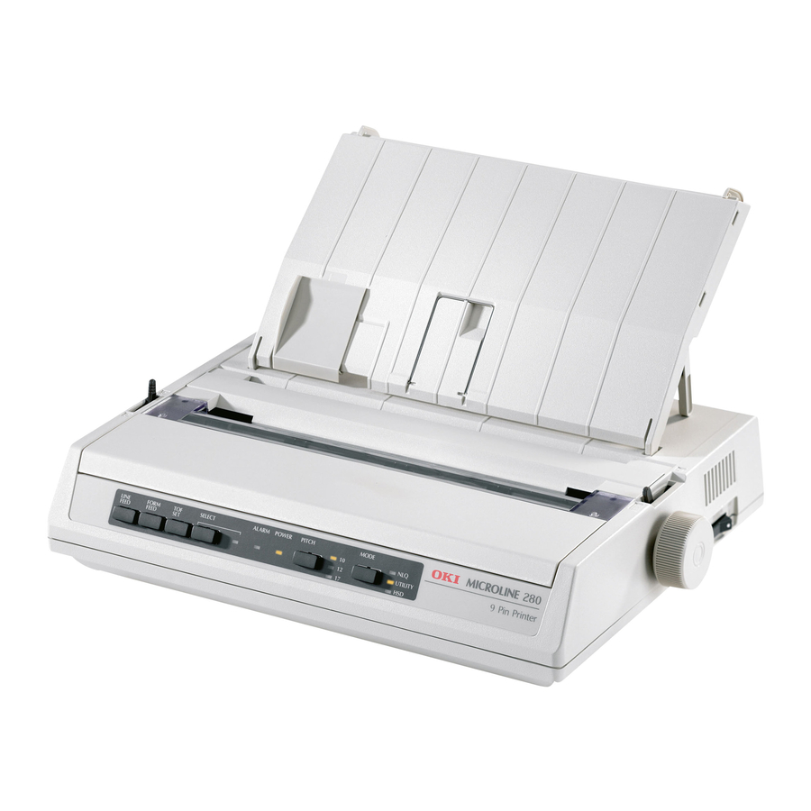
Посмотреть инструкция для OKI Microline 280 Elite бесплатно. Руководство относится к категории принтеры, 1 человек(а) дали ему среднюю оценку 7.5. Руководство доступно на следующих языках: английский. У вас есть вопрос о OKI Microline 280 Elite или вам нужна помощь? Задайте свой вопрос здесь
Не можете найти ответ на свой вопрос в руководстве? Вы можете найти ответ на свой вопрос ниже, в разделе часто задаваемых вопросов о OKI Microline 280 Elite.
Какой вес OKI Microline 280 Elite?
Как удалить замятую бумагу из принтера?
Почему после установки оригинального картриджа принтер не работает?
Чем обусловлено плохое качество печати?
В чем разница между лазерным и струйным принтером?
Почему при печати на струйном принтере появляются черные полосы?
Что означает аббревиатура DPI?
Инструкция OKI Microline 280 Elite доступно в русский?
Не нашли свой вопрос? Задайте свой вопрос здесь
- Manuals
- Brands
- Oki Manuals
- Printer
- ML280 Elite
- User manual
-
Contents
-
Table of Contents
-
Troubleshooting
-
Bookmarks
Quick Links
Related Manuals for Oki ML280 Elite
Summary of Contents for Oki ML280 Elite
-
Page 1
ML280 ELITE user’s guide… -
Page 2
The most up-to-date drivers and manuals are available from the Oki Europe website: http://www.okieurope.com Copyright © 2008. All rights reserved. -
Page 3: Table Of Contents
CONTENTS Introduction ……..6 Using this Manual .
-
Page 4
Index ……… . 49 Oki contact details ……. 51… -
Page 5
NOTES, CAUTIONS AND WARNINGS CAUTION! A caution appears in this manual like this. A caution provides additional information which, if ignored, may result in equipment malfunction or damage. WARNING! A warning appears in this manual like this. A warning provides additional information which, if ignored, may result in a risk of personal injury. -
Page 6: Introduction
User’s Guide to get the most from your printer. The ML280 Elite is an entry level 9 pin dot-matrix printer. It is fast, robust, compact and light. Outstanding reliability, compact size and…
-
Page 7: Online Usage
NLINE USAGE This manual is intended to be read on screen using Adobe Acrobat Reader. Use the navigation and viewing tools provided in Acrobat. You can access specific information in two ways: In the list of bookmarks down the left hand side of your screen, click on the topic of interest to jump to the required topic.
-
Page 8
Pages from and to for the range of pages you specify by entering their page numbers. Click on OK. INTRODUCTION > 8… -
Page 9: Getting Started
GETTING STARTED OCATION Select a firm, solid surface on which to site your printer. Allow enough space around the printer to easily access the platen knob and the various paper feed paths. Make sure a suitable grounded power outlet is available nearby.
-
Page 10: Removing The Shipping Restraint
Do not plug the printer into the AC supply until the following steps have been completed: EMOVING THE SHIPPING RESTRAINT Remove any packing tape. Insert your hand in the top cover slot (2) and remove the access cover (1) by lifting it. Remove the printhead shipping restraint.
-
Page 11: Installing/Replacing The Ribbon Cartridge
NSTALLING EPLACING THE IBBON ARTRIDGE CAUTION! When replacing a Ribbon Cartridge, make sure you have the correct replacement ribbon for your printer. The wrong ribbon will not print when installed in your printer. IBBON ARTRIDGE ANDLING Leave unused ribbon cartridges in their packages until needed.
-
Page 12
When replacing a Ribbon Cartridge, first remove the old one. WARNING! If you are replacing the ribbon Cartridge, the printhead may be HOT! Unpack the ribbon cartridge and install it on the printhead. GETTING STARTED > 12… -
Page 13: Installing The Platen Knob
Press gently on the ribbon cartridge until you feel it click into place. CAUTION! Do not remove the ribbon shield (“X” in graphic above) from the ribbon! Turn the take-up knob (a) in the direction of the moulded arrow to take up any ribbon slack. Replace the access cover.
-
Page 14: Adjusting The Head Gap
DJUSTING THE The head gap is the distance between the print head and the platen roller. When you use envelopes or multi-part forms you will need to have a larger gap than when using plain paper. Use the recommended head gap to ensure the best print quality and easy paper feed. CAUTION! Incorrect setting of the print head gap can cause print head damage or ribbon jams.
-
Page 15: Fitting The Paper Separator
ITTING THE APER EPARATOR The Paper Separator is utilised when using single sheets (no carbons) and when using continuous stationery to separate the ingoing/ outgoing paper to prevent paper jams. It is fitted as follows: Grasp the paper separator by either side, with the spring loaded stays to the rear of the printer.
-
Page 16: Setting Up Your Printer
SETTING UP YOUR PRINTER OWER ONNECTION Make sure both the printer and the computer are switched OFF. MODELS Plug the power cord into the back of the printer, then into a grounded AC outlet. Switch the Printer ON. MODELS With the printer switched OFF..Terminate the free ends of the power cord with connector(s) appropriate for connection to your DC voltage source.
-
Page 17: Loading Paper
Plug the power cord into the back of the printer and lock by twisting the collar of the connector clockwise. Switch the Printer ON. OADING APER Three types of paper can be used with your printer: Single sheet (with or without the optional cut sheet feeder) Roll paper (use the correct rollpaper stand) Fan-fold paper (with or without the optional tractor feed unit) When using fan-fold paper, adjust the distance between the sprocket…
-
Page 18
Remove the Access cover (1). Move the Bail arm lever (2) (on the left-hand side of the printer) to the front of the machine to lift the Bail bar. Move the Paper lever (3) (on the right-hand side of the printer) to the front of the machine, to the fan-fold symbol. -
Page 19
Push the paper in just enough so that its sprocket holes engage the sprocket pins located on the platen ends. Turn the Platen knob (5) to advance the paper until it appears in front of the platen. Move the Bail arm lever (2)to the rear of the machine to lower the Bail bar. -
Page 20: Bottom Feed Continuous Form Fan-Fold Paper
OTTOM FEED CONTINUOUS FORM FAN FOLD PAPER Ensure that the printer is switched OFF and the power supply lead removed. Place the printer on a slotted printer stand, carefully aligning the slot in the stand with the slot in the base of the printer. Place a box of fan-fold paper under the printer stand.
-
Page 21: Top Feed Single Sheet Paper
OP FEED SINGLE SHEET PAPER Your printer can accommodate single sheets of 216mm width x 297 or 355mm length paper. Remove the Tractor Feed unit and any other accessories, then raise the Paper Separator into its upright position. Switch the printer ON. Move the Paper lever (1) (on the right-hand side of the printer) to the rear of the machine, to the Blank sheet of paper symbol.
-
Page 22: Testing Your Printer
Hold down the LINE FEED button and turn the printer ON. The printer will begin its test print. To stop the test, press the SELECT button or turn the printer OFF. Typical test print: ML280 ELITE ME1 F/W XX.XX 42434401YR-00 XX.XX HSD 10CPI !”£$%^&*()0123456789:;<=>@aABCDEFGHIJKLMNOPQRSTUVWXYZ[]abcdefghijklm…
-
Page 23: Computer Connections
OMPUTER ONNECTIONS NOTE It is not recommended that you connect serial/USB and parallel cables to the printer simultaneously. For connection to a PC running Windows 98 or above (not Windows 95 upgraded to Windows 98) or Macintosh. The operation of a printer is not assured if a USB compatible device is connected concurrently with other USB compatible machines.
-
Page 24: Usb Connection
USB C ONNECTION Requires a USB 1.1 cable, maximum length 19.7 ft. (5 m), not supplied. Printer has a USB series “B” receptacle. NOTES For connection to a PC running Windows 98 or above (not Windows 95 upgraded to Windows 98). The operation of a printer is not assured if a USB compatible device is connected concurrently with other USB-compatible machines.
-
Page 25: Serial Connection
ERIAL ONNECTION The Serial Interface Board is an option on this printer and is supplied with installation and setup instructions. CAUTION! Make sure the printer and computer are both turned OFF. Switch both the computer and the printer OFF. Plug the cable into the serial ports of both your PC and printer and tighten the thumbscrews (1).
-
Page 26: Printer Drivers
RIVERS Printer drivers enable your computer to communicate with the printer. As with most printer manufacturers, Oki creates printer drivers for use with popular types of software, such as Microsoft Windows operating systems, from Windows 95 onwards. Installing a printer driver is normally a simple process of making a selection within the software.
-
Page 27: Operating Your Printer
OPERATING YOUR PRINTER RONT ANEL PERATION LINE FORM SELECT POWER PITCH ALARM FEED FEED MODE UTILITY The Front Panel has 9 indicators and 6 buttons. The function of each is as follows: Indicators SELECT Lit — Printer ON-LINE, unlit printer OFF-LINE. Flashes with ALARM on to indicate a fault has been detected.
-
Page 28
Additional button functions if pressed at Power ON LINE FEED Initiates the printer self test. SELECT and Initiates the printer’s continuous rolling ASCII test. LINE FEED SELECT and Places the printer into a Hex dump mode, printing all data and control FORM FEED commands received as HEX codes for fault finding. -
Page 29: Setting Printer Defaults
ETTING RINTER EFAULTS The printer has an internal MENU containing a number of default conditions that can be set to enable your printer to match the parameters required by your computer. MENU NTERING THE MODE Power on the printer while holding down the SELECT button. The 12 and UTILITY LEDs will flash.
-
Page 30: Default Menu Selections
EFAULT ENU SELECTIONS Group Item Setting Printer Control See the Printer Driver section of this document for more information. Font Print Mode Utility Draft Mode Pitch 10 CPI Proportional Spacing Style Normal Size Single Symbol Sets Character Set Set II Language Set ASCII Zero Character…
-
Page 31: Using The Pull Tractor Unit (If Fitted)
SING THE PULL RACTOR IF FITTED Paper can be loaded either from the rear of the printer or from the bottom if you have a slotted printer stand. Remove the access cover. Adjust the left tractor if necessary, making sure that it is not more than 12.7mm (0.5 inch) from the left-hand end of the tractor unit.
-
Page 32
Pull the paper under the Bail bar and up to the level of the tractor unit. Open the sprocket covers and slide the paper release lever forward. Locate the sprocket holes in the paper over the sprockets on the tractor unit and close both sprocket covers (leave the paper release lever open). -
Page 33: Using The Cut-Sheet Feeder (If Fitted)
SING THE SHEET EEDER IF FITTED Paper set lever Left paper guide Rear sheet support Front sheet support Right paper guide Front sheet guide Place the paper set lever (1) in the RESET position. Release the paper guides by pushing the locking levers downward.
-
Page 34: Manual Loading With The Cut-Sheet Feeder
Insert the paper stack into the hopper and push it against the left paper guide, making sure that the paper fits under the corner separators. Adjust the right paper guide to the paper width. Push both paper guide locking levers upward into the locked position.
-
Page 35: Cut-Sheet Feeder Controls
SHEET EEDER CONTROLS The printer’s control switches also control the operation of the cut- sheet feeder. The control switches, however, function only when the printer is off-line or deselected (SELECT indicator is not lit). SING THE APER TAND IF FITTED OADING THE APER Open the paper separator all the way.
-
Page 36
Feed the paper down behind the platen and use platen knob to bring paper through the printer. Lift the bail arm as paper comes round to front of platen. (The paper release lever needs to be in the top position to perform this step). -
Page 37: Maintenance
MAINTENANCE EPLACING THE IBBON ARTRIDGE “Installing/Replacing the Ribbon Cartridge’’on page 11 DJUSTING THE RINTHEAD “Adjusting the Head Gap’’on page 14 OADING APER “Loading Paper’’on page 17 ESTING YOUR PRINTER “Testing your printer’’on page 22 MAINTENANCE > 37…
-
Page 38: Troubleshooting
> Is the paper properly installed? > Is the ribbon properly installed? > Is an Oki ribbon being used? > Is the printhead gap correctly set? > Are the correct printer drivers being used for the printer? NOTE >…
-
Page 39
The initialization string contains codes that override the panel and menu settings. To change your printer to ignore the reset code, enter the Menu Mode, go to the Set-Up group and change the setting for Reset Inhibit to Yes. The I-Prime signal will automatically override any front panel settings you have made. -
Page 40
Check to be sure that the printer driver you have selected in your software matches the printer emulation. Please refer to the Printer Driver section for details of emulations, then check the menu settings (see “Setting Printer Defaults” in the Operating your Printer section). If you have embedded any printer commands in your software, check to be sure that you entered them correctly. -
Page 41
Solution The head gap may not be set correctly. Try moving the headgap lever to a lower setting. If that doesn’t help, the printhead may be damaged; call for service. Problem The ALARM light is flashing. Solution Try turning the printer OFF and then back ON again. If the light still blinks, call for service. -
Page 42: Clearing Paper Jams
LEARING APER Rear Feed Jams Turn the printer OFF. Use the platen knob to back the paper all the way out of the printer. CAUTION! Make sure the printer is turned OFF before you open the access cover. WARNING! The printhead may be HOT! Open the access cover, move the bail arm lever toward the front of the printer and remove any torn paper.
-
Page 43: Rear Feed, Repeating Paper Jams
Rear Feed, Repeating Paper Jams If the paper keeps jamming, you may have: > defective paper > misaligned paper > bits of paper in the paper path Defective Paper Replace the defective paper with a fresh stack. Misaligned Paper Turn the printer OFF. Use the platen knob to back the paper all the way out of the printer.
-
Page 44: Single Sheet Paper Jams
Single Sheet Paper Jams Turn off the printer. Use the platen knob to back the paper out. Open the access cover. Remove any torn pieces from around the carriage. Close the access cover. > 44…
-
Page 45: Parts And Accessories
Item descriptions and part numbers are provided in this section. Consult the dealer where you purchased your printer. Locate an Authorised Oki Data Reseller by visiting your local Oki web site. Links to all countries are provided on: http://www.okieurope.com…
-
Page 46: Options
OPTIONS Option Part number Pull Tractor Assembly (1) 09002363 Roll Paper Stand (2) 09002334 Cut Sheet Feeder (3) 09000689 Serial Interface Card, RS232 (4) 09002353 Serial Interface Card, RS422 (not shown) 09002357 Current Loop Interface Card (not shown) 09000685 All Accessories are supplied complete with an Installation Guide. PARTS AND ACCESSORIES >…
-
Page 47: Specifications
Print Method Impact dot matrix Printhead 9 pins, 0.30 mm (0.0118″) diameter, with thermal protection Emulations (co-resident) Epson FX IBM Graphics Oki MICROLINE Print Speed High Speed Draft (HSD) 333cps* Utility (UTL) 250cps* Near Letter Quality (NLQ) 62.5cps* * cps = characters per second…
-
Page 48
Item Specification Temperature Operating 5 to 40°C Storage -40 to +70°C) Humidity Operating 20 to 80% RH Storage 5 to 95% RH Interfaces: Standard: Centronics parallel, IEEE-1284 compliant USB 1.1 Optional: RS-232C Serial RS-422 Current Loop SPECIFICATIONS > 48… -
Page 49: Index
INDEX Front Panel ………27 Access cover……18 Additional button functions if Graphics……..30 pressed at Power ON….28 ALARM……..27 Auto CR ……..30 Humidity……..48 Auto LF ……..30 Auto Select ………30 Impact Mode…….30 Initialization string……38 Bail arm lever……. 18 Installing the Ribbon Cartridge ..11 Bi — Direction…….30 I-Prime ……..
-
Page 50
Paper Specifications ….47 SELECT ……..27 Parallel (LPT) Connection…..23 SELECT and FORM FEED ….28 Parallel Interface SELECT and LINE FEED ….28 I-PRIME Signal ……38 Serial Cable Connection ….25 Pin 18………30 Serial Interface Option ….39 PITCH ………27 Setting Printer Defaults ….29 POWER ……..27 Skip Over Perforation ….30 Power Connection …. -
Page 51: Oki Contact Details
Fax : (64) 9 477 0549 Tel : (81) 3 5445 6158 http://www.comworth.co.nz Fax : (81) 3 5445 6189 http://www.okidata.co.jp Oki Data (S) P Ltd. Malaysia Rep Office Oki Data (Singapore) Pte. Ltd. Suite 21.03, 21st Floor Menara IGB, 78 Shenton Way, #09-01,…
-
Page 52
ML280 ELITE Blays House Wick Road, Egham Surrey, TW20 0HJ United Kingdom tel +44 (0) 20 8219 2190 Fax +44 (0) 20 8219 2199 07051001 ISS.02…
Просмотр
Доступно к просмотру 53 страницы. Рекомендуем вам скачать файл инструкции, поскольку онлайн просмотр документа может сильно отличаться от оригинала.
-
ML280 ELITE
руководство польэователч
-
Авторы настоящей инструкции приложили все усилия с целью обеспечения
полноты, точности и актуальности приведенной информации.  Вместе с тем,
производитель не несет ответственности за последствия ошибок, находящихся вне
его контроля. Производитель также не может гарантировать, что изменения
программ и оборудования, внесенные другими производителями и упомянутые в
настоящем документе, не повлияют на правильность приведенной здесь
информации.  Упоминание программных продуктов других компаний не
предполагает безусловного их одобрения со стороны производителя.
Несмотря на то, что были приложены все возможные усилия для обеспечения
максимальной точности и полезности настоящего документа, мы не даем никаких
явных либо подразумеваемых гарантий в отношении точности и полноты
содержащейся в нем информации.
Самые последние версии драйверов и руководств пользователя можно скачать с
сайта Oki Europe по адресу:
http://www.okieurope.com
Copyright © 2008. Все права охраняются.
Oki и Microline – это зарегистрированные товарные знаки компании Oki Electric
Industry Company Ltd.
Energy Star является товарным знаком Агентства по защите окружающей среды
США.
Hewlett-Packard, HP и LaserJet являются зарегистрированными товарными знаками
компании Hewlett-Packard.
Microsoft, MS-DOS и Windows являются зарегистрированными товарными знаками
компании Microsoft Corporation.
Apple, Macintosh и Mac OS – это зарегистрированные товарные знаки компании
Apple Computer Inc.
Другие наименования продуктов и фирменных названий являются
зарегистрированными товарными знаками их владельцев.
Являясь участником программы Energy Star, производитель
установил, что его продукт соответствует требованиям данной
программы в отношении эффективного использования энергии.
Примечание:
Energy Star не относится к версии DC данного продукта.
Настоящий продукт соответствует требованиям директив Совета
Европы 89/336/EEC (EMC) и 73/23/EEC (LVD) с применимыми
изменениями, связанными с приведением в соответствие законов
стран-членов Сообщества об электромагнитной совместимости и
низком напряжении.
Предисловие > 2
-
Содержание
Введение . . . . . . . . . . . . . . . . . . . . . . . . . . . . . . . . . . . . . . . .6
Пользование настоящим руководством. . . . . . . . . . . 6
Использование в интерактивном режиме . . . . . . 7
Печать страниц. . . . . . . . . . . . . . . . . . . . . . . . . . . . . 7
Приступая к работе . . . . . . . . . . . . . . . . . . . . . . . . . . . . . . .9
Размещение принтера  . . . . . . . . . . . . . . . . . . . . . . . . . 9
Содержимое и распаковка. . . . . . . . . . . . . . . . . . . . . . 9
Удаление транспортных ограничителей. . . . . . . . . .10
Установка/замена картриджа с лентой . . . . . . . . . .11
Обращение с картриджем с лентой. . . . . . . . . . .11
Установка  круглой ручки. . . . . . . . . . . . . . . . . . . . . .13
Регулировка зазора головки . . . . . . . . . . . . . . . . . . .14
Установка разделителя бумаги . . . . . . . . . . . . . . . . .15
Установка принтера. . . . . . . . . . . . . . . . . . . . . . . . . . . . . .16
Подключение питания. . . . . . . . . . . . . . . . . . . . . . . . .16
Для моделей переменного тока: . . . . . . . . . . . . .16
Для моделей постоянного тока: . . . . . . . . . . . . . .16
Загрузка бумаги  . . . . . . . . . . . . . . . . . . . . . . . . . . . . .17
Задняя подача фальцованной бумаги. . . . . . . . .17
Нижняя подача фальцованной бумаги . . . . . . . .20
Верхняя подача отдельных листов  . . . . . . . . . . .21
Проверка принтера . . . . . . . . . . . . . . . . . . . . . . . . . . .22
Подключение к компьютеру. . . . . . . . . . . . . . . . . . . .23
Подключение к параллельному порту (LPT),
IEEE 1284. . . . . . . . . . . . . . . . . . . . . . . . . . . . . . . . .23
Подключение USB  . . . . . . . . . . . . . . . . . . . . . . . . .24
Последовательное подключение . . . . . . . . . . . . .25
Драйверы принтера  . . . . . . . . . . . . . . . . . . . . . . . . . .26
Работа с принтером . . . . . . . . . . . . . . . . . . . . . . . . . . . . . .27
Работа с передней панелью . . . . . . . . . . . . . . . . . . . .27
Задание параметров принтера по умолчанию  . . . .29
Вход в режим MENU (МЕНЮ). . . . . . . . . . . . . . . . .29
Выбор настроек меню по умолчанию . . . . . . . . .30
Использование устройства непрерывной
подачи (если оно установлено) . . . . . . . . . . . . . . . . .31
Использование устройства подачи отдельных
листов (если установлено) . . . . . . . . . . . . . . . . . . . . .33
Содержание > 3
- 1
- 2
- 3
- 4
- 53
ML280 ELITE
user’s guide
Every effort has been made to ensure that the information in this document is complete, accurate, and up-to-date. The manufacturer assumes no responsibility for the results of errors beyond its control. The manufacturer also cannot guarantee that changes in software and equipment made by other manufacturers and referred to in this Guide will not affect the applicability of the information in it. Mention of software products manufactured by other companies does not necessarily constitute endorsement by the manufacturer.
While all reasonable efforts have been made to make this document as accurate and helpful as possible, we make no warranty of any kind, expressed or implied, as to the accuracy or completeness of the information contained herein.
The most up-to-date drivers and manuals are available from the Oki Europe website:
http://www.okieurope.com
Copyright © 200
8. All rights reserved.
Oki and Microline are registered trademarks of Oki Electric Industry Company Ltd.
Energy Star is a trademark of the United States Environmental Protection Agency.
Hewlett-Packard, HP, and LaserJet are registered trademarks of Hewlett-Packard
Company.
Microsoft, MS-DOS and Windows are registered trademarks of Microsoft Corporation.
Apple, Macintosh and Mac OS are registered trademarks of Apple Computer Inc.
Other product names and brand names are registered trademarks or trademarks of their proprietors.
As an Energy Star Program Participant, the manufacturer has determined that this product meets the Energy Star guidelines for energy efficiency.
NOTE
Energy Star does not apply to the DC version of this product.
This product complies with the requirements of the Council Directives
89/336/EEC (EMC) and 73/23/EEC (LVD) as amended where applicable on the approximation of the laws of the member states relating to electromagnetic compatibility and low voltage.
PREFACE > 2
CONTENTS
Introduction . . . . . . . . . . . . . . . . . . . . . . . . . . . . . . . . . . . . . .6
Using this Manual . . . . . . . . . . . . . . . . . . . . . . . . . . . . . . 6
Online usage . . . . . . . . . . . . . . . . . . . . . . . . . . . . . . . 7
Printing Pages . . . . . . . . . . . . . . . . . . . . . . . . . . . . . . 7
Getting Started . . . . . . . . . . . . . . . . . . . . . . . . . . . . . . . . . . .9
Location . . . . . . . . . . . . . . . . . . . . . . . . . . . . . . . . . . . . . . 9
Contents and Unpacking . . . . . . . . . . . . . . . . . . . . . . . . 9
Removing the shipping restraint . . . . . . . . . . . . . . . . . 10
Installing/Replacing the Ribbon Cartridge . . . . . . . . . 11
Ribbon Cartridge Handling . . . . . . . . . . . . . . . . . . . 11
Installing the Platen Knob . . . . . . . . . . . . . . . . . . . . . . 13
Adjusting the Head Gap . . . . . . . . . . . . . . . . . . . . . . . . 14
Fitting the Paper Separator . . . . . . . . . . . . . . . . . . . . . 15
Setting up your Printer . . . . . . . . . . . . . . . . . . . . . . . . . . . .16
Power Connection . . . . . . . . . . . . . . . . . . . . . . . . . . . . . 16
For AC models:. . . . . . . . . . . . . . . . . . . . . . . . . . . . . 16
For DC models:. . . . . . . . . . . . . . . . . . . . . . . . . . . . . 16
Loading Paper . . . . . . . . . . . . . . . . . . . . . . . . . . . . . . . . 17
Rear feed continuous form fan-fold paper . . . . . . . 17
Bottom feed continuous form fan-fold paper . . . . 20
Top feed single sheet paper . . . . . . . . . . . . . . . . . . 21
Testing your printer. . . . . . . . . . . . . . . . . . . . . . . . . . . . 22
Computer Connections . . . . . . . . . . . . . . . . . . . . . . . . . 23
Parallel (LPT) Connection, IEEE 1284 . . . . . . . . . . . 23
USB Connection. . . . . . . . . . . . . . . . . . . . . . . . . . . . 24
Serial Connection . . . . . . . . . . . . . . . . . . . . . . . . . . 25
Printer Drivers . . . . . . . . . . . . . . . . . . . . . . . . . . . . . . . . 26
Operating your Printer . . . . . . . . . . . . . . . . . . . . . . . . . . . .27
Front Panel Operation . . . . . . . . . . . . . . . . . . . . . . . . . . 27
Setting Printer Defaults . . . . . . . . . . . . . . . . . . . . . . . . 29
Entering the MENU mode . . . . . . . . . . . . . . . . . . . . 29
Default Menu selections . . . . . . . . . . . . . . . . . . . . . 30
Using the pull Tractor Unit (if fitted) . . . . . . . . . . . . . . 31
Using the Cut-sheet Feeder (if fitted) . . . . . . . . . . . . . . 33
manual loading with the Cut-sheet Feeder installed. . . . . . . . . . . . . . . . . . . . . . . . . . . . . . . . . 34
Cut-sheet Feeder controls . . . . . . . . . . . . . . . . . . . . 35
CONTENTS > 3
Using the Roll Paper Stand (if fitted) . . . . . . . . . . . . . . 35
Loading the Paper . . . . . . . . . . . . . . . . . . . . . . . . . . 35
Maintenance . . . . . . . . . . . . . . . . . . . . . . . . . . . . . . . . . . . .37
Replacing the Ribbon Cartridge . . . . . . . . . . . . . . . . . . 37
Adjusting the Printhead Gap . . . . . . . . . . . . . . . . . . . . 37
Loading Paper . . . . . . . . . . . . . . . . . . . . . . . . . . . . . . . . 37
Testing your printer. . . . . . . . . . . . . . . . . . . . . . . . . . . . 37
Troubleshooting . . . . . . . . . . . . . . . . . . . . . . . . . . . . . . . . .38
General Information . . . . . . . . . . . . . . . . . . . . . . . . . . . 38
Clearing Paper Jams . . . . . . . . . . . . . . . . . . . . . . . . . . . 42
Rear Feed Jams . . . . . . . . . . . . . . . . . . . . . . . . . . . . 42
Rear Feed, Repeating Paper Jams. . . . . . . . . . . . . . 43
Single Sheet Paper Jams . . . . . . . . . . . . . . . . . . . . . 44
Parts and Accessories . . . . . . . . . . . . . . . . . . . . . . . . . . . . .45
Purchasing Parts & Accessories. . . . . . . . . . . . . . . . . . 45
Options . . . . . . . . . . . . . . . . . . . . . . . . . . . . . . . . . . . . . 46
Specifications . . . . . . . . . . . . . . . . . . . . . . . . . . . . . . . . . . .47
Index . . . . . . . . . . . . . . . . . . . . . . . . . . . . . . . . . . . . . . . . . . 49
Oki contact details . . . . . . . . . . . . . . . . . . . . . . . . . . . . . . . 51
CONTENTS > 4
NOTES, CAUTIONS AND WARNINGS
CAUTION!
A caution appears in this manual like this. A caution provides additional information which, if ignored, may result in equipment malfunction or damage.
WARNING!
A warning appears in this manual like this. A warning provides additional information which, if ignored, may result in a risk of personal injury.
NOTE
A note appears like this. A note provides additional information to supplement the main text.
CONTENTS > 5
INTRODUCTION
Congratulations on purchasing this Oki printer!
In this chapter you will find a summary of the main features of your printer followed by some advice on how to use this User’s Guide to get the most from your printer.
The ML280 Elite is an entry level 9 pin dot-matrix printer. It is fast, robust, compact and light. Outstanding reliability, compact size and ease of use make it ideal for industrial workstation applications, as well as customer service points in wholesale, retail and service environments.
U
SING THIS
M
ANUAL
This manual will lead you logically through the unpacking, setting up and operation of your printer to help you to make the best use of its many advanced features. Also included are guidelines for troubleshooting and maintenance to ensure that it continues to perform at its best. Instructions are also provided for adding optional accessories as your needs evolve.
l
The User’s Guide has been written using one printer as a model, and the illustrations/screenshots reflect this. What you see will be appropriate to the model you are installing.
l
The User’s Guide has been designed to provide you with a clear presentation on the installation and maintenance of your new printer. This information is compiled in the logical sequence required to result in a successful installation.
NOTE
l
The information in this manual is supplemented by the extensive online help facility associated with the printer driver software.
l
In addition, we provide a Technical Reference Guide for those users requiring more in-depth Technical information. This is available in
English only.
INTRODUCTION > 6
O
NLINE USAGE
This manual is intended to be read on screen using Adobe Acrobat
Reader. Use the navigation and viewing tools provided in Acrobat.
You can access specific information in two ways:
l
In the list of bookmarks down the left hand side of your screen, click on the topic of interest to jump to the required topic. (If the bookmarks are not available, use the Table of Contents).
l
In the list of bookmarks click on Index to jump to the Index. (If the bookmarks are not available, use the Table of Contents).
Find the term of interest in the alphabetically arranged index and click on the associated page number to jump to the page containing the subject.
P
RINTING
P
AGES
The whole book, individual pages, or sections may be printed. The procedure is:
1.
From the toolbar, select [File], then [Print] (or press the
Ctrl + P keys).
2.
Choose which pages you wish to print:
(a)
All pages, for the entire manual.
(b)
Current page for the page at which you are looking.
INTRODUCTION > 7
(c)
Pages from and to for the range of pages you specify by entering their page numbers.
3.
Click on
OK.
INTRODUCTION > 8
GETTING STARTED
L
OCATION
l
Select a firm, solid surface on which to site your printer.
l
Allow enough space around the printer to easily access the platen knob and the various paper feed paths.
l
Make sure a suitable grounded power outlet is available nearby.
l
Read the Installation Safety Booklet.
C
ONTENTS AND
U
NPACKING
l
If any items are missing, contact your dealer immediately.
l
Keep your packing materials and carton in case you ever need to ship or transport the printer.
3b
3a
5
4
1
6
8
10
7
9
1. Printer
2. Ribbon Cartridge
6.
Installation Safety booklet
7.
Pan European limited Warranty
3. Power Cord(s) — AC (3a);DC (3b) 8.
Manual CD
4. Platen Knob 9.
Driver CD
5. Sheet Separator 10. Setup Guide
2
GETTING STARTED > 9
Do not plug the printer into the AC supply until the following steps have been completed:
R
EMOVING THE SHIPPING RESTRAINT
1.
Remove any packing tape. Insert your hand in the top cover slot (2) and remove the access cover (1) by lifting it.
2
1
2.
Remove the printhead shipping restraint. Keep shipping restraint for future use.
3.
Reinstall the access cover.
GETTING STARTED > 10
I
NSTALLING
/R
EPLACING THE
R
IBBON
C
ARTRIDGE
CAUTION!
When replacing a Ribbon Cartridge, make sure you have the correct replacement ribbon for your printer. The wrong ribbon will not print when installed in your printer.
R
IBBON
C
ARTRIDGE
H
ANDLING
l
Leave unused ribbon cartridges in their packages until needed.
l
Careful; the ribbon ink may cause permanent stains.
l
Ribbon ink on skin or clothing can usually be removed with soap and water.
Make sure the printer is turned OFF.
1.
Open the access cover and center the printhead (1).
GETTING STARTED > 11
2.
When replacing a Ribbon Cartridge, first remove the old one.
WARNING!
If you are replacing the ribbon Cartridge, the printhead may be HOT!
3.
Unpack the ribbon cartridge and install it on the printhead.
1
2
3
X
GETTING STARTED > 12
4.
Press gently on the ribbon cartridge until you feel it click into place.
CAUTION!
Do not remove the ribbon shield ( “X” in graphic above) from the ribbon!
5.
Turn the take-up knob (a) in the direction of the moulded arrow to take up any ribbon slack.
a
6.
Replace the access cover.
I
NSTALLING THE
P
LATEN
K
NOB
If the Platen Knob is not already fitted, align the key way (a) correctly and push it firmly into place.
a
GETTING STARTED > 13
A
DJUSTING THE
H
EAD
G
AP
The head gap is the distance between the print head and the platen roller. When you use envelopes or multi-part forms you will need to have a larger gap than when using plain paper. Use the recommended head gap to ensure the best print quality and easy paper feed.
CAUTION!
Incorrect setting of the print head gap can cause print head damage or ribbon jams. To avoid these problems set the print head gap for the type of stationery being used.
To adjust the print head gap, move the coloured lever located to the left of the ribbon cartridge (a), to the correct position for the type of stationery being used……
a
…..as detailed in the following table:
Paper Type
Single part paper
Form
Two part
Three part
Four part
Weight
14 — 20lb (52 — 75gm)
Lever position
1, 2
9 — 11 lb. (35 — 40 gm) with a maximum thickness of 0.28mm
2 — 3
3
3
GETTING STARTED > 14
F
ITTING THE
P
APER
S
EPARATOR
The Paper Separator is utilised when using single sheets (no carbons) and when using continuous stationery to separate the ingoing/ outgoing paper to prevent paper jams. It is fitted as follows:
1.
Grasp the paper separator by either side, with the spring loaded stays to the rear of the printer.
2.
Locate the two hooked lugs on the edges of the paper separator into the two corresponding slots in the top of the printer.
3.
Release paper separator on to the top of the printer.
GETTING STARTED > 15
SETTING UP YOUR PRINTER
P
OWER
C
ONNECTION
Make sure both the printer and the computer are switched OFF.
F
OR
AC
MODELS
:
1.
Plug the power cord into the back of the printer, then into a grounded AC outlet.
2.
Switch the Printer ON.
F
OR
DC
MODELS
:
With the printer switched OFF…..
1.
Terminate the free ends of the power cord with connector(s) appropriate for connection to your DC voltage source.
WARNING!
Observe polarity of connection!
SETTING UP YOUR PRINTER > 16
2.
Plug the power cord into the back of the printer and lock by twisting the collar of the connector clockwise.
3
2
3.
Switch the Printer ON.
L
OADING
P
APER
Three types of paper can be used with your printer:
l
Single sheet (with or without the optional cut sheet feeder)
l
Roll paper (use the correct rollpaper stand)
l
Fan-fold paper (with or without the optional tractor feed unit)
When using fan-fold paper, adjust the distance between the sprocket pins at the ends of the platen to the holes in the paper. Fan-fold paper can be fed from the rear of the printer, or, if a slotted stand is available, from underneath.
R
EAR FEED CONTINUOUS FORM FAN
—
FOLD PAPER
Ensure that the printer is switched OFF and the power supply lead removed.
1.
Place a box of fan-fold paper behind the printer.
SETTING UP YOUR PRINTER > 17
2.
Remove the Access cover (1).
3
2
1
3.
Move the
Bail arm lever (2) (on the left-hand side of the printer) to the front of the machine to lift the
Bail bar.
4.
Move the
Paper lever (3) (on the right-hand side of the printer) to the front of the machine, to the
fan-fold symbol.
5.
Insert the first sheet of paper between the separator paper guides (4).
4
2
3
5
SETTING UP YOUR PRINTER > 18
Push the paper in just enough so that its sprocket holes engage the sprocket pins located on the platen ends.
6.
Turn the Platen knob (5) to advance the paper until it appears in front of the platen.
7.
Move the Bail arm lever (2)to the rear of the machine to lower the Bail bar.
8.
Use the Platen knob (5) to advance the paper to the first printing line.
9.
Replace the Access cover and switch the printer ON.
SETTING UP YOUR PRINTER > 19
B
OTTOM FEED CONTINUOUS FORM FAN
—
FOLD PAPER
Ensure that the printer is switched OFF and the power supply lead removed.
1.
Place the printer on a slotted printer stand, carefully aligning the slot in the stand with the slot in the base of the printer.
2.
Place a box of fan-fold paper under the printer stand.
3.
Remove the
Access cover.
4.
Move the Bail arm lever (2) (on the left-hand side of the printer) to the front of the machine to lift the Bail bar.
5.
Move the Paper lever (3) (on the right-hand side of the printer) to the front of the machine, to the fan-fold symbol.
6.
Insert the first sheet of paper through the opening in the printer stand and the bottom of the printer.
7.
Adjust the Platen sprocket(s) to align with the sprocket holes in the paper.
8.
Use the Platen knob to gently pull the paper up until it appears in front of the platen, and above the Bail bar
9.
Move the Bail arm lever to the rear of the machine to lower the
Bail bar (6).
10.
Use the Platen knob (5) to advance the paper to the first printing line.
11.
Replace the Access cover and switch the printer ON.
SETTING UP YOUR PRINTER > 20
T
OP FEED SINGLE SHEET PAPER
Your printer can accommodate single sheets of 216mm width x 297 or
355mm length paper. Remove the Tractor Feed unit and any other accessories, then raise the Paper Separator into its upright position.
1
3
2
1.
Switch the printer ON.
2.
Move the Paper lever (1) (on the right-hand side of the printer) to the rear of the machine, to the Blank sheet of paper symbol.
3.
Ensure that the printer is OFF-LINE (press the SELECT switch if necessary).
Make sure the Bail arm lever (2) is set to the rear of the machine
(in its closed position).
4.
Raise the paper separator as shown above.
5.
Adjust the Cut Sheet guide (3) on the Paper Separator to position the left edge of the sheet.
NOTE
If letter size paper is used, set the cut sheet guide to the line mark on the paper separator. 80 character width text (10cpi) is then positioned centrally on the paper.
SETTING UP YOUR PRINTER > 21
6.
Insert a single sheet along the Cut Sheet guide until it reaches the pinch roller. Be sure to keep the paper inside the platen ends, otherwise the built-in sprocket rollers will tear it.
7.
Move the Bail arm lever (2) towards the front of the machine, into the open position. The sheet of paper will be pulled around the platen.
8.
Close the Bail arm lever (2) ensuring that the paper has been positioned correctly.
9.
Press the SELECT button to bring the printer ON-LINE.
10.
The sprockets can be released and moved out from the platen if required.
T
ESTING YOUR PRINTER
Your printer has a built-in test (self test) to make sure that your printer is set up and working correctly.
1.
Firstly, load continuous forms paper into the printer (Please see the “Loading Paper” section of this Guide).
2.
Hold down the LINE FEED button and turn the printer ON.
The printer will begin its test print.
3.
To stop the test, press the SELECT button or turn the printer
OFF.
Typical test print:
ML280 ELITE ME1 F/W XX.XX
CG XX.XX
42434401YR-00
HSD 10CPI
!ӣ$%^&*()0123456789:;<=>@aABCDEFGHIJKLMNOPQRSTUVWXYZ[]abcdefghijklm nopqrstuvwxyz
NOTE
The top of each print test contains information about your printer model.
Be sure to have a copy of the printout handy if you have to call for service.
SETTING UP YOUR PRINTER > 22
C
OMPUTER
C
ONNECTIONS
NOTE
l
It is not recommended that you connect serial/USB and parallel cables to the printer simultaneously.
l
For connection to a PC running Windows 98 or above (not Windows
95 upgraded to Windows 98) or Macintosh.
l
The operation of a printer is not assured if a USB compatible device is connected concurrently with other USB compatible machines.
l
Interface cables are not supplied with your printer.
P
ARALLEL
(LPT) C
ONNECTION
, IEEE 1284
l
Requires a bi-directional cable, max. length 6 ft. (1.8 m), not supplied
l
The printer has a 36-pin Centronics type socket.
CAUTION!
Make sure the printer and computer are both turned OFF.
1.
Switch both the computer and the printer OFF.
2.
Attach a suitable bi-directional cable to the parallel connector on the back of the printer. Then attach and secure the cable to your computer.
3.
Turn the printer and computer back ON.
SETTING UP YOUR PRINTER > 23
USB C
ONNECTION
l
Requires a USB 1.1 cable, maximum length 19.7 ft. (5 m), not supplied.
l
Printer has a USB series “B” receptacle.
NOTES
l
For connection to a PC running Windows 98 or above (not Windows
95 upgraded to Windows 98).
l
The operation of a printer is not assured if a USB compatible device is connected concurrently with other USB-compatible machines.
l
When connecting multiple printers of the same type, they appear as
*****, ***** (2), ***** (3), etc. These numbers depend on the order of connecting or turning on each printer.
l
USB is a “hot-pluggable” protocol. This means that the printer and
computer do not necessarily have to be switched OFF.
1.
Attach a suitable USB cable to the printer. Then attach the cable to your computer.
2.
If you have turned the computer and printer OFF, turn them back ON.
Follow any on-screen insructions.
SETTING UP YOUR PRINTER > 24
S
ERIAL
C
ONNECTION
The Serial Interface Board is an option on this printer and is supplied with installation and setup instructions.
CAUTION!
Make sure the printer and computer are both turned OFF.
1.
2.
Switch both the computer and the printer OFF.
Plug the cable into the serial ports of both your PC and printer and tighten the thumbscrews (1).
1
The cable should comply with the RS232C Serial Interface
Specification and have a maximum length of 15 metres (49ft).
3.
Turn the printer and computer back
ON.
SETTING UP YOUR PRINTER > 25
P
RINTER
D
RIVERS
Printer drivers enable your computer to communicate with the printer.
As with most printer manufacturers, Oki creates printer drivers for use with popular types of software, such as Microsoft Windows operating systems, from Windows 95 onwards. Installing a printer driver is normally a simple process of making a selection within the software.
If a driver is not available by name for your printer, contact the software manufacturer and ask if they can supply an updated version of their software with additional drivers. Alternatively, check the driver availability on the Oki Europe Web Site at:
www.okieurope.com
If you are using bespoke software or software created specifically for your company, it is unlikely that the CDs supplied with this software will include drivers for your printer. In this instance you will have to choose a driver as closely compatible as possible. Compatible drivers contain printing codes that will operate your printer. They may not offer the special features of an original driver, but they will allow you to perform normal printing tasks.
Oki’s printers contain more than one printer emulation selectable via the menu system. See the table below for compatible drivers.
However, please note that the emulations listed toward the bottom of this list are more basic and offer fewer of the printer’s features.
Microline
Emulation
ML280 Microline
IBM Emulation
ML280 IBM
IBM Graphics Printer
Epson LQ Emulation
ML280 Epson
Epson FX80
Epson FX
SETTING UP YOUR PRINTER > 26
OPERATING YOUR PRINTER
F
RONT
P
ANEL
O
PERATION
LINE
FEED
FORM
FEED
TOF
SET
SELECT
ALARM
POWER PITCH 10
12
17
MODE
NLQ
UTILITY
HSD
The Front Panel has 9 indicators and 6 buttons. The function of each is as follows:
Indicators
SELECT
ALARM
Lit — Printer ON-LINE, unlit printer OFF-LINE. Flashes with ALARM on to indicate a fault has been detected.
l
If lit permanently and SELECT is not lit — it is indicating paper out or paper jam if a Cut Sheet Feeder is in use.
POWER
PITCH
MODE l
If lit permanently and SELECT is flashing — it is indicating that auto diagnostics have detected an error.
l
If flashing and SELECT is lit — it is indicating either printhead temperature protection circuit, firmware protection of line feed or space motor is operating. In any case, normal print operation will resume after a cooling period.
Indicates that the printer is connected to the supply and is switched ON.
Indicates the current character pitch selected.
Indicates the current print mode selected — NLQ, Utility, HSD (HSD is SSD if 12cpi is selected).
Buttons
LINE FEED
Advances the paper one line for each press.
FORM FEED Advances the paper to the next top of form (TOF) or ejects any single sheet paper from the printer.
TOF SET
SELECT
PITCH
MODE
Sets new top of form (TOF) position.
Places printer ON or OFF line
Changes the character pitch setting (cpi)
Changes the print style setting.
OPERATING YOUR PRINTER > 27
Additional button functions if pressed at Power ON
LINE FEED
SELECT and
LINE FEED
SELECT and
FORM FEED
SELECT
TOF SET
Initiates the printer self test.
Initiates the printer’s continuous rolling ASCII test.
Places the printer into a Hex dump mode, printing all data and control commands received as HEX codes for fault finding.
Enters the printer’s Menu Mode.
Selects the print pitch as 17cpi.
OPERATING YOUR PRINTER > 28
S
ETTING
P
RINTER
D
EFAULTS
The printer has an internal MENU containing a number of default conditions that can be set to enable your printer to match the parameters required by your computer.
E
NTERING THE
MENU
MODE
1.
Power on the printer while holding down the SELECT button.
The 12 and UTILITY LEDs will flash.
2.
Press the SELECT button to print the complete menu. This will detail the current default settings.
3.
Press the LINE FEED button to select the relevant group that needs to be changed (the group is the left-hand column on the
MENU printout).
4.
Press the FORM FEED button to select the relevant item within the selected group (the Item is the centre column on the MENU printout).
5.
Press the TOF SET button to cycle through the settings available for the item you want to change (the settings are the right-hand column on the MENU printout).
6.
Once you have reached the setting that you want, press either the LINE FEED button (for the next group) or the FORM FEED button (for the next item) to be changed.
Follow steps to 3 to 5 until all your required settings have been changed.
7.
On completion of the changes, press the PITCH and MODE buttons together to exit and save all the changes you have made.
NOTE
Important, do not exit the menu mode by switching off the printer, as this will not save any changes you have made.
OPERATING YOUR PRINTER > 29
D
EFAULT
M
ENU SELECTIONS
Group Item Setting
Printer Control See the Printer Driver section of this document for more information.
IBM
Font Print Mode
Draft Mode
Pitch
Proportional Spacing
Style
Size
Utility
SSD
10 CPI
No
Normal
Single
Symbol Sets Character Set
Language Set
Zero Character
Code Page
Slashed Letter O
Vertical
Control
Line Spacing
Skip Over Perforation
Page Length
Set-up
Parallel I/F
Graphics
Receive Buffer Size
Paper out Override
Print Registration
Operator Panel Function
Reset Inhibit
Printer Suppress Effective
Auto LF
Auto CR
S1 Select Pitch (10 CPI)
S1 Select Pitch (12 CPI)
Time Out Print
Auto Select
ESC/S1 Pitch
CSF/RPS Pitch
Impact Mode
I — Prime
Pin 18
Bi — Direction
Set II
ASCII
Unslashed
USA
No
6 LPI
No
12″
Uni-directional
64K
No
0
Semi Operation
No
Yes
No
Yes
17.1 CPI
20 CPI
Valid
No
17.1
RPS
Normal
Buffer Print
+5V
Enable
OPERATING YOUR PRINTER > 30
U
SING THE PULL
T
RACTOR
U
NIT
(
IF FITTED
)
Paper can be loaded either from the rear of the printer or from the bottom if you have a slotted printer stand.
1.
Remove the access cover.
A
B
2.
Adjust the left tractor if necessary, making sure that it is not more than 12.7mm (0.5 inch) from the left-hand end of the tractor unit. To move the tractor, pull the lock lever forward, slide the tractor to the desired position, then push the lock lever backward to lock it in place.
A
B
3.
Adjust the right tractor to the paper width by pulling its lock lever forward, sliding the tractor to the desired position, then pushing the lock lever backward to lock it in place.
OPERATING YOUR PRINTER > 31
4.
Pull the paper under the Bail bar and up to the level of the tractor unit.
5.
Open the sprocket covers and slide the paper release lever forward.
A
B
6.
Locate the sprocket holes in the paper over the sprockets on the tractor unit and close both sprocket covers (leave the paper release lever open).
7.
Replace the access cover.
OPERATING YOUR PRINTER > 32
U
SING THE
C
UT
—
SHEET
F
EEDER
(
IF FITTED
)
3
4
5
2
1
6
1.
2.
3.
4.
5.
6.
Paper set lever
Left paper guide
Rear sheet support
Front sheet support
Right paper guide
Front sheet guide
1.
Place the paper set lever (1) in the RESET position.
2.
Release the paper guides by pushing the locking levers downward.
3.
Move the left paper guide (2) to the position where you wish to set the left-hand edge of the sheet, making sure that this paper guide is not set to the right of the paper out sensor (the groove in the platen).
4.
“Flex” a paper stack (not more than 170 sheets of 60g/m²
(
16lb.) paper
).
Square the stack, turn over and repeat the bending. The stack of paper should not exceed 16mm thickness.
OPERATING YOUR PRINTER > 33
5.
Insert the paper stack into the hopper and push it against the
left paper guide, making sure that the paper fits under the corner separators.
6.
Adjust the right paper guide to the paper width.
7.
Push both paper guide locking levers upward into the locked position.
8.
Push the paper set lever (1) gently backward into the set position.
MANUAL LOADING WITH THE
C
UT
—
SHEET
F
EEDER INSTALLED
.
1.
Gently insert the paper from directly above the
front sheet
support.
2.
Use the FORM FEED button to feed the sheet.
3.
Turn the Platen knob clockwise/anti-clockwise for fine adjustment.
NOTE
The manually set sheet is printed automatically, even when other sheets are loaded in the hopper. When the FORM FEED button is pressed, the manually inserted sheet will be fed from the cut-sheet feeder.
CAUTION!
l
Do not manually feed paper if a sheet is being fed from the hopper. Simultaneous feeding of paper will result in a paper jam.
l
To manually feed a sheet of paper, you must use the FORM FEED button to feed the paper. If the paper is being fed manually and is positioned using the platen knob rather than the FORM FEED button, it may be ejected just before printing begins (use the
Platen Knob for fine adjustment only).
OPERATING YOUR PRINTER > 34
C
UT
—
SHEET
F
EEDER CONTROLS
The printer’s control switches also control the operation of the cutsheet feeder. The control switches, however, function only when the printer is off-line or deselected (SELECT indicator is not lit).
U
SING THE
R
OLL
P
APER
S
TAND
(
IF FITTED
)
L
OADING THE
P
APER
1.
Open the paper separator all the way.
2.
Remove the paper roller.
Note that there is a disk on the left end of the roller.
3.
Slide the roller into a tube of paper.
Ensure the disk is on the left side and paper must roll up from the bottom.
4.
Replace the paper roller back into the stand, with the disc on the left side.
5.
Feed the paper over the roller on the stand.
NOT UNDER!
6.
Adjust the round paper guides at either side to the paper width.
OPERATING YOUR PRINTER > 35
7.
Feed the paper down behind the platen and use platen knob to bring paper through the printer.
Lift the bail arm as paper comes round to front of platen. (The paper release lever needs to be in the top position to perform this step).
8.
Continue to feed the paper through for approx. 4 inches.
9.
Move the paper release lever toward the front of the machine.
Align the paper so that the exit and entry paper edges align.
Return the paper release lever to the rear position to re-apply pressure on platen.
10.
Close the bail arm.
11.
Replace the access cover. Fit the cover tabs into the slots at the printer front. Lower the cover carefully, making sure the paper fits through the front slot in the access cover.
12.
Lower the paper separator so that paper enters the printer from under the separator and exits the printer going over the separator (see below).
13.
Turn the platen knob to move the paper to the point where you want printing to start. (Many word processing packages automatically allow for a top margin of 25.4mm (1 inch)).
a b c
a Paper roll c Platen
d
Correct paper path b Roll Paper Stand d Paper Guide
OPERATING YOUR PRINTER > 36
MAINTENANCE
R
EPLACING THE
R
IBBON
C
ARTRIDGE
See
“Installing/Replacing the Ribbon Cartridge’’on page 11 .
A
DJUSTING THE
P
RINTHEAD
G
AP
See
“Adjusting the Head Gap’’on page 14
L
OADING
P
APER
See
“Loading Paper’’on page 17
T
ESTING YOUR PRINTER
See
“Testing your printer’’on page 22
MAINTENANCE > 37
TROUBLESHOOTING
G
ENERAL
I
NFORMATION
>
>
>
>
>
>
Here are some general things to check before proceeding with detailed troubleshooting.
>
Is the printer plugged in and turned ON?
Are the connections (power and interface) secure?
>
Is the product being operated under the proper ambient conditions?
Does the paper being used meet the specifications for this product?
Is the paper properly installed?
Is the ribbon properly installed?
Is an Oki ribbon being used?
Is the printhead gap correctly set?
>
Are the correct printer drivers being used for the printer?
NOTE
> Settings in your software application will normally override any settings in your printer driver.
> Printer driver settings normally override settings from the printer menu or printer front panel.
Problem
My word processor files do not print the way I have the menu and front panel set.
Solution
Remember: The note above!
Before sending a file to the printer, many word processors send either an “initialization string” or an I-Prime signal to the printer.
> 38
The initialization string contains codes that override the panel and menu settings. To change your printer to ignore the reset code, enter the Menu Mode, go to the Set-Up group and change the setting for
Reset Inhibit to Yes.
The I-Prime signal will automatically override any front panel settings you have made. To eliminate this problem, enter the Menu Mode, go to the Parallel Interface group and change the setting for I-Prime to
Invalid.
For more information on changing menu settings, see “Changing the
Menu Settings” in Chapter 3.
Problem
Nothing happens when I turn ON the printer.
Solution
Check the power cord connection to the outlet and to the printer. If you are using a power strip, make sure it is turned ON, and that the fuse hasn’t blown or that the circuit breaker hasn’t tripped. If the solution is not obvious — call for service.
Problem
The printer does not print when the computer sends data.
Solutions
1.
Is the SEL light on? If not, press the SEL key.
2.
Check that the interface cable is securely connected to both the printer and the computer.
3.
If you have the optional serial interface board installed, check to be sure that it is firmly seated in the printer and that the interface cable is securely connected to both the printer and the computer.
Problem
I’m getting strange symbols, incorrect fonts, etc., when I try to print a document.
Solutions
> 39
1.
Check to be sure that the printer driver you have selected in your software matches the printer emulation.
2.
Please refer to the Printer Driver section for details of emulations, then check the menu settings (see “Setting Printer
Defaults” in the Operating your Printer section).
3.
If you have embedded any printer commands in your software, check to be sure that you entered them correctly.
Problem
Ink smears on the paper when I print narrow columns.
Solutions
The head gap could be too close. Check that the head gap is set correctly (see the table in “Adjusting the head gap” in the
Getting
Started section).
Problem
I’ve installed a new ribbon and the printing is smeared and streaked.
Solution
The ribbon shield (1) is either loose or missing.
1
Remove the ribbon cartridge and check the ribbon shield.
If it is loose, secure it. If it is missing, find it and install it. If you cannot find it, replace the ribbon cartridge.
Tip: If you still have an old ribbon cartridge, remove the shield from it and install it on the ribbon cartridge on your printer.
Problem
There are dots missing in my printouts (typically, tops and /or bottom of characters missing).
> 40
Solution
The head gap may not be set correctly. Try moving the headgap lever to a lower setting. If that doesn’t help, the printhead may be damaged; call for service.
Problem
The ALARM light is flashing.
Solution
Try turning the printer OFF and then back ON again. If the light still blinks, call for service.
Problem
The Print Quality and Character Pitch keys on the front panel don’t work.
Solution
The Operator Panel Function in the printer menu can be used to disable these buttons (Limited Function). If the printer is part of a customized system or if it is used by a number of people, the system manager may have used this option to make sure the printer is always set properly.
Check with your system manager before changing any menu settings.
Problem
My printer keeps indicating “Paper out” when there is paper installed.
Solution
The most likely cause is that the paper sensor groove in the platen is not being covered by paper. Re-align paper to cover the sensor groove.
Problem
When I am using continuous feed paper, the sprocket holes are torn, causing alignment problems.
Solution
The most likely cause is that the paper lever is set to friction feed.
Move the lever to “Fan-fold” (to the front of the printer)
> 41
C
LEARING
P
APER
J
AMS
Rear Feed Jams
1.
Turn the printer OFF.
2.
Use the platen knob to back the paper all the way out of the printer.
CAUTION!
Make sure the printer is turned OFF before you open the access cover.
WARNING!
The printhead may be HOT!
3.
Open the access cover, move the bail arm lever toward the front of the printer and remove any torn paper.
4.
Reload the paper (see section on “Maintenance”), move the bail arm lever towards the rear of the printer and close the access cover.
5.
Turn the printer ON.
> 42
Rear Feed, Repeating Paper Jams
>
>
If the paper keeps jamming, you may have:
>
defective paper misaligned paper bits of paper in the paper path
Defective Paper
Replace the defective paper with a fresh stack.
Misaligned Paper
1.
Turn the printer OFF.
2.
Use the platen knob to back the paper all the way out of the printer.
3.
Tear off a couple of sheets of paper, leaving a new, clean, square-cut edge.
4.
Reload the paper and turn the printer back ON.
Bits of paper in the paper path
Depending on which paper feed method you are using, remove any accessories, open the access cover and remove any debris from the paper path.
WARNING!
l
Always ensure that the printer is switched OFF and that the power supply lead is disconnected.
l
If the printer has been recently used, the printhead may be HOT!
> 43
Single Sheet Paper Jams
1.
Turn off the printer.
2.
Use the platen knob to back the paper out.
3.
Open the access cover.
4.
Remove any torn pieces from around the carriage.
5.
Close the access cover.
> 44
PARTS AND ACCESSORIES
PURCHASING PARTS & ACCESSORIES
Before you purchase parts and accessories, make a note of your printer model name (see the front of the unit) and have the correct part number and description of the item you wish to purchase. Item descriptions and part numbers are provided in this section.
l
Consult the dealer where you purchased your printer.
l
Locate an Authorised Oki Data Reseller by visiting your local
Oki web site. Links to all countries are provided on:
http://www.okieurope.com
5
3 x 2
4
2
1
7
6
Item
Ribbon Cartridge (1)
Platen Knob (2)
Power Cord AC (3) — Euro
UK
Power Cord DC (7)
Printhead (4)
Access Cover (5)
Sheet Guide (6)
Part number Comment
09002303
3PB4043-2156P7
YS4011-1272P001
YS4011-1273P001
YS4100-1187P001
42666401
3PA4017-3044P10
2PA4017-337864
Life — 3 million characters
Life — 200 million characters
PARTS AND ACCESSORIES > 45
OPTIONS
1
2
3
4
Option
Pull Tractor Assembly (1)
Roll Paper Stand (2)
Cut Sheet Feeder (3)
Serial Interface Card, RS232 (4)
Serial Interface Card, RS422 (not shown)
Current Loop Interface Card (not shown)
Part number
09002363
09002334
09000689
09002353
09002357
09000685
All Accessories are supplied complete with an Installation Guide.
PARTS AND ACCESSORIES > 46
SPECIFICATIONS
Item Specification
Print Method
Printhead
Emulations (co-resident)
Impact dot matrix
9 pins, 0.30 mm (0.0118″) diameter, with thermal protection
Epson FX
IBM Graphics
Oki MICROLINE
Print Speed
High Speed Draft (HSD)
Utility (UTL)
Near Letter Quality (NLQ)
Reliability
Ribbon Life (black)
Printhead Life
333cps*
250cps*
62.5cps*
* cps = characters per second
Paper Specifications
Type
Cut Sheets
Feed
Top only
Single part Continuous Rear/Bottom
Multi Part Continuous Rear/Bottom
Maximum thickness
Maximum number of sheets
Weight
16 to 21lb. (60 to 81g/m²)
Width (range)
14 to 20lb. (53 to 75g/m²) 3 to 9.5 inches
14 to 20lb. (53 to 75g/m²) 3 to 9.5 inches
0.28mm (0.11 inches)
4 (original plus 3 copies) carbonless
3 million characters, on average
200 million characters average in 10cpi utility mode
Mean Time Between
Failures (MTBF)
Mean Time to Repair
(MTTR)
20,000 hours at 25% duty cycle and 35% page density
15 minutes
General Printer Characteristics
Dimensions
Weight
Buffer size
Noise level
Power requirements
Height: 80mm (height) x 372mm (width) x 275mm (depth)
4.5Kg
128Kb
<54dBA and <51dBA in Quiet Mode
AC — 230VAC (+6%;-14%), 240VAC (±10%;) @50/60Hz (±2%)
DC — 9.6VDC <-> 31.2VDC, 4.0 <-> 1.8A
SPECIFICATIONS > 47
Item
Temperature
Operating
Storage
Humidity
Operating
Storage
Interfaces:
Standard:
Optional:
Specification
5 to 40°C
-40 to +70°C)
20 to 80% RH
5 to 95% RH
Centronics parallel, IEEE-1284 compliant
USB 1.1
RS-232C Serial
RS-422
Current Loop
SPECIFICATIONS > 48
INDEX
A
Access cover…………………… 18
,
20
Additional button functions if
pressed at Power ON……………….28
ALARM………………………………….27
Auto CR ………………………………..30
Auto LF …………………………………30
Auto Select ……………………………30
B
Bail arm lever………………….. 18
,
20
Bi — Direction………………………….30
blank sheet of paper symbol …….21
Bottom feed continuous form fan-
fold paper……………………………..20
C
Centering printhead position…….40
Character Set…………………………30
Clearing Paper Jams ………………..42
Code Page …………………………….30
Computer Connections…………….23
CSF/RPS Pitch………………………..30
Current Loop………………………….48
Cut Sheet feeder …………………….21
E
ESC/S1 Pitch …………………………30
F
Fanfold ………………………….. 18
,
20
Fitting the Paper Separator……….15
Fonts
Embedded Printer Commands ..40
FORM FEED ……………………………27
Front Panel ……………………………27
G
Graphics……………………………….30
H
Humidity……………………………….48
I
Impact Mode………………………….30
Initialization string………………….38
Installing the Ribbon Cartridge ….11
I-Prime ………………………….. 30
,
38
L
Language Set…………………………30
Limited Operation …………………..41
LINE FEED ………………………. 27
,
28
Line Spacing ………………………….30
Loading Paper………………………..17
M
Mean Time Between Failures
(MTBF) ………………………………….47
Mean Time to Repair (MTTR) ……..47
MODE …………………………………..27
O
Operator Panel……………………….30
Operator Panel Function …………..41
P
Page Length…………………………..30
paper lever ……………….. 18
,
20
,
21
Paper out Override ………………….30
Paper Separator……………………..21
INDEX > 49
Paper Specifications ……………….47
Parallel (LPT) Connection………….23
Parallel Interface
I-PRIME Signal …………………….38
Pin 18…………………………………..30
PITCH …………………………………..27
POWER …………………………………27
Power Connection ……………. 16
,
23
Print Method………………………….47
Print Registration ……………………30
Print Speed……………………………47
Printer Drivers………………………..30
Printer Suppress Effective ………..30
Printhead ……………………………..47
R
Rear feed continuous form fan-fold
paper …………………………………..17
Receive Buffer Size …………………30
Removing the shipping restraint ..10
Reset Inhibit ………………………….30
Ribbon Shield …………………. 13
,
40
RS-232C Serial Interface ………….48
RS-422 …………………………………48
S
S1 Select Pitch (10 CPI) ……………30
S1 Select Pitch (12 CPI) ……………30
SELECT …………………………………27
SELECT and FORM FEED ……………28
SELECT and LINE FEED ……………..28
Serial Cable Connection …………..25
Serial Interface Option …………….39
Setting Printer Defaults ……………29
Skip Over Perforation ………………30
Software
Embedded commands ………….40
Software vs. printer settings ….38
T
Time Out Print………………………..30
TOF SET …………………………. 27
,
28
Top feed single sheet paper ……..21
Tractor Feed unit …………………….21
U
Unpacking ………………………………9
USB Connection ……………………..24
Using the Cut-Sheet Feeder ………33
Using the Cut-sheet Feeder……….33
Using the pull Tractor Unit ………..31
Using the Roll Paper Stand ……….35
Z
Zero Character ……………………….30
INDEX > 50
OKI CONTACT DETAILS
Oki Systems (UK) Limited
550 Dundee Road
Slough Trading Estate
Slough, SL1 4LE
Tel :44 (0) 1753 819819
Fax :44 (0) 1753 819899 www.okiprintingsolutions.co.uk
Oki Systems Ireland Limited
The Square Industrial Complex
Tallaght, Dublin 24, Ireland
Tel :+353 1 4049590
Fax :+353 1 4049591 http://www.oki.ie
OKI Systems Northern Ireland
40 Sydenham Park
Belfast, BT4 1PW
Tel :+44 (0) 28 90 20 1110 http://www.oki.ie
Technical Support for all of Ireland:
Tel : +353 1 4049570
Fax : +353 1 4049555
E-mail: [email protected]
Oki Data Corporation
4-11-22 Shibaura, Minato-ku, Tokyo
108-8551, Japan
Tel : (81) 3 5445 6158
Fax : (81) 3 5445 6189 http://www.okidata.co.jp
Oki Data (Singapore) Pte. Ltd.
78 Shenton Way, #09-01,
Singapore 079120
Tel : (65) 221 3722
Fax : (65)421 1688 http://www.okidata.com.sg
Oki Systems (Thailand) Ltd.
1168/81-82 Lumpini Tower, 27th
Floor, Rama IV Rd, Tungmahamek,
Sathorn, Bangkok 10120
Tel : +662 6799235
Fax : +662 6799245 http://www.okisysthai.com/oki
Oki Hong Kong Limited
Unit 607, 6/F,
Island Place Tower,
510 Kings Road, North Point, Hong
Kong
Tel : (852) 3543 9200
Fax : (852) 3549 6040
The IPL Group
146 O’Riordan Street
Mascot NSW 2020, Australia
Tel : (61) 2 9667 7000
Fax : (61) 2 9667 7094 http://www.oki.com.au
Comworth Systems Ltd.
10 Constellation Drive
Mairangi Bay, Auckland,
New Zealand
Tel : (64) 9 477 0500
Fax : (64) 9 477 0549 http://www.comworth.co.nz
Oki Data (S) P Ltd. Malaysia Rep
Office
Suite 21.03, 21st Floor Menara IGB,
Mid Valley City,
Lingkaran Syed Pura 59200,
Kuala Lumpur, Malaysia
Tel: (60) 3 2287 1177
Fax: (60) 3 2287 1166
OKI CONTACT DETAILS > 51
ML280 ELITE
Blays House
Wick Road, Egham
Surrey, TW20 0HJ
United Kingdom tel +44 (0) 20 8219 2190
Fax +44 (0) 20 8219 2199
07051001 ISS.02
View a manual of the OKI Microline 280 Elite below. All manuals on ManualsCat.com can be viewed completely free of charge. By using the ‘Select a language’ button, you can choose the language of the manual you want to view.
Page: 1
PREFACE > 2
Every effort has been made to ensure that the information in this document is complete,
accurate, and up-to-date. The manufacturer assumes no responsibility for the results of
errors beyond its control. The manufacturer also cannot guarantee that changes in
software and equipment made by other manufacturers and referred to in this Guide will
not affect the applicability of the information in it. Mention of software products
manufactured by other companies does not necessarily constitute endorsement by the
manufacturer.
While all reasonable efforts have been made to make this document as accurate and
helpful as possible, we make no warranty of any kind, expressed or implied, as to the
accuracy or completeness of the information contained herein.
The most up-to-date drivers and manuals are available from the Oki Europe website:
http://www.okieurope.com
Copyright © 2008. All rights reserved.
Oki and Microline are registered trademarks of Oki Electric Industry Company Ltd.
Energy Star is a trademark of the United States Environmental Protection Agency.
Hewlett-Packard, HP, and LaserJet are registered trademarks of Hewlett-Packard
Company.
Microsoft, MS-DOS and Windows are registered trademarks of Microsoft Corporation.
Apple, Macintosh and Mac OS are registered trademarks of Apple Computer Inc.
Other product names and brand names are registered trademarks or trademarks of
their proprietors.
As an Energy Star Program Participant, the manufacturer has
determined that this product meets the Energy Star guidelines for
energy efficiency.
This product complies with the requirements of the Council Directives
89/336/EEC (EMC) and 73/23/EEC (LVD) as amended where applicable
on the approximation of the laws of the member states relating to
electromagnetic compatibility and low voltage.
NOTE
Energy Star does not apply to the DC version of this product.
Page: 2
CONTENTS > 3
CONTENTS
Introduction . . . . . . . . . . . . . . . . . . . . . . . . . . . . . . . . . . . . . .6
Using this Manual. . . . . . . . . . . . . . . . . . . . . . . . . . . . . . 6
Online usage . . . . . . . . . . . . . . . . . . . . . . . . . . . . . . . 7
Printing Pages . . . . . . . . . . . . . . . . . . . . . . . . . . . . . . 7
Getting Started . . . . . . . . . . . . . . . . . . . . . . . . . . . . . . . . . . .9
Location. . . . . . . . . . . . . . . . . . . . . . . . . . . . . . . . . . . . . . 9
Contents and Unpacking . . . . . . . . . . . . . . . . . . . . . . . . 9
Removing the shipping restraint . . . . . . . . . . . . . . . . .10
Installing/Replacing the Ribbon Cartridge . . . . . . . . .11
Ribbon Cartridge Handling . . . . . . . . . . . . . . . . . . .11
Installing the Platen Knob . . . . . . . . . . . . . . . . . . . . . .13
Adjusting the Head Gap . . . . . . . . . . . . . . . . . . . . . . . .14
Fitting the Paper Separator . . . . . . . . . . . . . . . . . . . . .15
Setting up your Printer . . . . . . . . . . . . . . . . . . . . . . . . . . . .16
Power Connection . . . . . . . . . . . . . . . . . . . . . . . . . . . . .16
For AC models:. . . . . . . . . . . . . . . . . . . . . . . . . . . . .16
For DC models:. . . . . . . . . . . . . . . . . . . . . . . . . . . . .16
Loading Paper . . . . . . . . . . . . . . . . . . . . . . . . . . . . . . . .17
Rear feed continuous form fan-fold paper. . . . . . .17
Bottom feed continuous form fan-fold paper . . . .20
Top feed single sheet paper . . . . . . . . . . . . . . . . . .21
Testing your printer. . . . . . . . . . . . . . . . . . . . . . . . . . . .22
Computer Connections . . . . . . . . . . . . . . . . . . . . . . . . .23
Parallel (LPT) Connection, IEEE 1284 . . . . . . . . . . .23
USB Connection. . . . . . . . . . . . . . . . . . . . . . . . . . . .24
Serial Connection . . . . . . . . . . . . . . . . . . . . . . . . . .25
Printer Drivers . . . . . . . . . . . . . . . . . . . . . . . . . . . . . . . .26
Operating your Printer . . . . . . . . . . . . . . . . . . . . . . . . . . . .27
Front Panel Operation. . . . . . . . . . . . . . . . . . . . . . . . . .27
Setting Printer Defaults . . . . . . . . . . . . . . . . . . . . . . . .29
Entering the MENU mode . . . . . . . . . . . . . . . . . . . .29
Default Menu selections . . . . . . . . . . . . . . . . . . . . .30
Using the pull Tractor Unit (if fitted) . . . . . . . . . . . . . .31
Using the Cut-sheet Feeder (if fitted). . . . . . . . . . . . . .33
manual loading with the Cut-sheet Feeder
installed. . . . . . . . . . . . . . . . . . . . . . . . . . . . . . . . .34
Cut-sheet Feeder controls. . . . . . . . . . . . . . . . . . . .35
Page: 3
CONTENTS > 4
Using the Roll Paper Stand (if fitted) . . . . . . . . . . . . . .35
Loading the Paper . . . . . . . . . . . . . . . . . . . . . . . . . .35
Maintenance . . . . . . . . . . . . . . . . . . . . . . . . . . . . . . . . . . . .37
Replacing the Ribbon Cartridge . . . . . . . . . . . . . . . . . .37
Adjusting the Printhead Gap . . . . . . . . . . . . . . . . . . . .37
Loading Paper . . . . . . . . . . . . . . . . . . . . . . . . . . . . . . . .37
Testing your printer. . . . . . . . . . . . . . . . . . . . . . . . . . . .37
Troubleshooting . . . . . . . . . . . . . . . . . . . . . . . . . . . . . . . . .38
General Information . . . . . . . . . . . . . . . . . . . . . . . . . . .38
Clearing Paper Jams . . . . . . . . . . . . . . . . . . . . . . . . . . .42
Rear Feed Jams . . . . . . . . . . . . . . . . . . . . . . . . . . . .42
Rear Feed, Repeating Paper Jams. . . . . . . . . . . . . .43
Single Sheet Paper Jams. . . . . . . . . . . . . . . . . . . . .44
Parts and Accessories. . . . . . . . . . . . . . . . . . . . . . . . . . . . .45
Purchasing Parts & Accessories. . . . . . . . . . . . . . . . . .45
Options . . . . . . . . . . . . . . . . . . . . . . . . . . . . . . . . . . . . .46
Specifications . . . . . . . . . . . . . . . . . . . . . . . . . . . . . . . . . . .47
Index . . . . . . . . . . . . . . . . . . . . . . . . . . . . . . . . . . . . . . . . . .49
Oki contact details . . . . . . . . . . . . . . . . . . . . . . . . . . . . . . .51
Page: 4
CONTENTS > 5
NOTES, CAUTIONS AND WARNINGS
CAUTION!
A caution appears in this manual like this. A caution provides
additional information which, if ignored, may result in equipment
malfunction or damage.
WARNING!
A warning appears in this manual like this. A warning provides
additional information which, if ignored, may result in a risk of
personal injury.
NOTE
A note appears like this. A note provides additional information to
supplement the main text.
Page: 5
INTRODUCTION > 6
INTRODUCTION
Congratulations on purchasing this Oki printer!
In this chapter you will find a summary of the main features of your
printer followed by some advice on how to use this User’s Guide to get
the most from your printer.
The ML280 Elite is an entry level 9 pin dot-matrix printer. It is fast,
robust, compact and light. Outstanding reliability, compact size and
ease of use make it ideal for industrial workstation applications, as
well as customer service points in wholesale, retail and service
environments.
USING THIS MANUAL
This manual will lead you logically through the unpacking, setting up
and operation of your printer to help you to make the best use of its
many advanced features. Also included are guidelines for
troubleshooting and maintenance to ensure that it continues to
perform at its best. Instructions are also provided for adding optional
accessories as your needs evolve.
l The User’s Guide has been written using one printer as a
model, and the illustrations/screenshots reflect this. What you
see will be appropriate to the model you are installing.
l The User’s Guide has been designed to provide you with a
clear presentation on the installation and maintenance of your
new printer. This information is compiled in the logical
sequence required to result in a successful installation.
NOTE
l The information in this manual is supplemented by the extensive
online help facility associated with the printer driver software.
l In addition, we provide a Technical Reference Guide for those users
requiring more in-depth Technical information. This is available in
English only.
Page: 6
INTRODUCTION > 7
ONLINE USAGE
This manual is intended to be read on screen using Adobe Acrobat
Reader. Use the navigation and viewing tools provided in Acrobat.
You can access specific information in two ways:
l In the list of bookmarks down the left hand side of your screen,
click on the topic of interest to jump to the required topic. (If
the bookmarks are not available, use the Table of Contents).
l In the list of bookmarks click on Index to jump to the Index. (If
the bookmarks are not available, use the Table of Contents).
Find the term of interest in the alphabetically arranged index
and click on the associated page number to jump to the page
containing the subject.
PRINTING PAGES
The whole book, individual pages, or sections may be printed. The
procedure is:
1. From the toolbar, select [File], then [Print] (or press the
Ctrl + P keys).
2. Choose which pages you wish to print:
(a) All pages, for the entire manual.
(b) Current page for the page at which you are looking.
Page: 7
INTRODUCTION > 8
(c) Pages from and to for the range of pages you specify by
entering their page numbers.
3. Click on OK.
Page: 8
GETTING STARTED > 9
GETTING STARTED
LOCATION
l Select a firm, solid surface on which to site your printer.
l Allow enough space around the printer to easily access the
platen knob and the various paper feed paths.
l Make sure a suitable grounded power outlet is available
nearby.
l Read the Installation Safety Booklet.
CONTENTS AND UNPACKING
l If any items are missing, contact your dealer immediately.
l Keep your packing materials and carton in case you ever need
to ship or transport the printer.
1. Printer 6. Installation Safety booklet
2. Ribbon Cartridge 7. Pan European limited Warranty
3. Power Cord(s) — AC (3a);DC (3b) 8. Manual CD
4. Platen Knob 9. Driver CD
5. Sheet Separator 10. Setup Guide
1
2
3a
4
5
6
7
8
9
10
3b
Page: 9
GETTING STARTED > 10
Do not plug the printer into the AC supply until the following steps
have been completed:
REMOVING THE SHIPPING RESTRAINT
1. Remove any packing tape. Insert your hand in the top cover
slot (2) and remove the access cover (1) by lifting it.
2. Remove the printhead shipping restraint. Keep shipping
restraint for future use.
3. Reinstall the access cover.
2
1
Page: 10
GETTING STARTED > 11
INSTALLING/REPLACING THE RIBBON CARTRIDGE
RIBBON CARTRIDGE HANDLING
l Leave unused ribbon cartridges in their packages until
needed.
l Careful; the ribbon ink may cause permanent stains.
l Ribbon ink on skin or clothing can usually be removed with
soap and water.
Make sure the printer is turned OFF.
1. Open the access cover and center the printhead (1).
CAUTION!
When replacing a Ribbon Cartridge, make sure you have the correct
replacement ribbon for your printer. The wrong ribbon will not print
when installed in your printer.
Page: 11
GETTING STARTED > 12
2. When replacing a Ribbon Cartridge, first remove the old one.
3. Unpack the ribbon cartridge and install it on the printhead.
WARNING!
If you are replacing the ribbon Cartridge, the printhead may be HOT!
1
2
3
X
Page: 12
GETTING STARTED > 13
4. Press gently on the ribbon cartridge until you feel it click into
place.
5. Turn the take-up knob (a) in the direction of the moulded arrow
to take up any ribbon slack.
6. Replace the access cover.
INSTALLING THE PLATEN KNOB
If the Platen Knob is not already fitted, align the key way (a) correctly
and push it firmly into place.
CAUTION!
Do not remove the ribbon shield (“X” in graphic above) from the
ribbon!
a
a
Page: 13
GETTING STARTED > 14
ADJUSTING THE HEAD GAP
The head gap is the distance between the print head and the platen
roller. When you use envelopes or multi-part forms you will need to
have a larger gap than when using plain paper. Use the recommended
head gap to ensure the best print quality and easy paper feed.
To adjust the print head gap, move the coloured lever located to the
left of the ribbon cartridge (a), to the correct position for the type of
stationery being used……
…..as detailed in the following table:
CAUTION!
Incorrect setting of the print head gap can cause print head damage
or ribbon jams. To avoid these problems set the print head gap for the
type of stationery being used.
Paper Type Weight Lever position
Single part paper 14 — 20lb (52 — 75gm) 1, 2
Form
Two part
Three part
Four part
9 — 11 lb. (35 — 40 gm) with a
maximum thickness of 0.28mm
2 — 3
3
3
a
Page: 14
GETTING STARTED > 15
FITTING THE PAPER SEPARATOR
The Paper Separator is utilised when using single sheets (no carbons)
and when using continuous stationery to separate the ingoing/
outgoing paper to prevent paper jams. It is fitted as follows:
1. Grasp the paper separator by either side, with the spring
loaded stays to the rear of the printer.
2. Locate the two hooked lugs on the edges of the paper
separator into the two corresponding slots in the top of the
printer.
3. Release paper separator on to the top of the printer.
Page: 15
SETTING UP YOUR PRINTER > 16
SETTING UP YOUR PRINTER
POWER CONNECTION
Make sure both the printer and the computer are switched OFF.
FOR AC MODELS:
1. Plug the power cord into the back of the printer, then into a
grounded AC outlet.
2. Switch the Printer ON.
FOR DC MODELS:
With the printer switched OFF…..
1. Terminate the free ends of the power cord with connector(s)
appropriate for connection to your DC voltage source.
WARNING!
Observe polarity of connection!
Page: 16
SETTING UP YOUR PRINTER > 17
2. Plug the power cord into the back of the printer and lock by
twisting the collar of the connector clockwise.
3. Switch the Printer ON.
LOADING PAPER
Three types of paper can be used with your printer:
l Single sheet (with or without the optional cut sheet feeder)
l Roll paper (use the correct rollpaper stand)
l Fan-fold paper (with or without the optional tractor feed unit)
When using fan-fold paper, adjust the distance between the sprocket
pins at the ends of the platen to the holes in the paper. Fan-fold paper
can be fed from the rear of the printer, or, if a slotted stand is
available, from underneath.
REAR FEED CONTINUOUS FORM FAN-FOLD PAPER
Ensure that the printer is switched OFF and the power supply lead
removed.
1. Place a box of fan-fold paper behind the printer.
2
3
Page: 17
SETTING UP YOUR PRINTER > 18
2. Remove the Access cover (1).
3. Move the Bail arm lever (2) (on the left-hand side of the
printer) to the front of the machine to lift the Bail bar.
4. Move the Paper lever (3) (on the right-hand side of the printer)
to the front of the machine, to the fan-fold symbol.
5. Insert the first sheet of paper between the separator paper
guides (4).
2
1
3
4
5
2
3
Page: 18
SETTING UP YOUR PRINTER > 19
Push the paper in just enough so that its sprocket holes
engage the sprocket pins located on the platen ends.
6. Turn the Platen knob (5) to advance the paper until it appears
in front of the platen.
7. Move the Bail arm lever (2)to the rear of the machine to lower
the Bail bar.
8. Use the Platen knob (5) to advance the paper to the first
printing line.
9. Replace the Access cover and switch the printer ON.
Page: 19
SETTING UP YOUR PRINTER > 20
BOTTOM FEED CONTINUOUS FORM FAN-FOLD PAPER
Ensure that the printer is switched OFF and the power supply lead
removed.
1. Place the printer on a slotted printer stand, carefully aligning
the slot in the stand with the slot in the base of the printer.
2. Place a box of fan-fold paper under the printer stand.
3. Remove the Access cover.
4. Move the Bail arm lever (2) (on the left-hand side of the
printer) to the front of the machine to lift the Bail bar.
5. Move the Paper lever (3) (on the right-hand side of the printer)
to the front of the machine, to the fan-fold symbol.
6. Insert the first sheet of paper through the opening in the
printer stand and the bottom of the printer.
7. Adjust the Platen sprocket(s) to align with the sprocket holes
in the paper.
8. Use the Platen knob to gently pull the paper up until it appears
in front of the platen, and above the Bail bar
9. Move the Bail arm lever to the rear of the machine to lower the
Bail bar (6).
10. Use the Platen knob (5) to advance the paper to the first
printing line.
11. Replace the Access cover and switch the printer ON.
Page: 20
SETTING UP YOUR PRINTER > 21
TOP FEED SINGLE SHEET PAPER
Your printer can accommodate single sheets of 216mm width x 297 or
355mm length paper. Remove the Tractor Feed unit and any other
accessories, then raise the Paper Separator into its upright position.
1. Switch the printer ON.
2. Move the Paper lever (1) (on the right-hand side of the printer)
to the rear of the machine, to the Blank sheet of paper symbol.
3. Ensure that the printer is OFF-LINE (press the SELECT switch if
necessary).
Make sure the Bail arm lever (2) is set to the rear of the machine
(in its closed position).
4. Raise the paper separator as shown above.
5. Adjust the Cut Sheet guide (3) on the Paper Separator to
position the left edge of the sheet.
NOTE
If letter size paper is used, set the cut sheet guide to the line mark on the
paper separator. 80 character width text (10cpi) is then positioned
centrally on the paper.
1
2
3
Page: 21
SETTING UP YOUR PRINTER > 22
6. Insert a single sheet along the Cut Sheet guide until it reaches
the pinch roller. Be sure to keep the paper inside the platen
ends, otherwise the built-in sprocket rollers will tear it.
7. Move the Bail arm lever (2) towards the front of the machine,
into the open position. The sheet of paper will be pulled
around the platen.
8. Close the Bail arm lever (2) ensuring that the paper has been
positioned correctly.
9. Press the SELECT button to bring the printer ON-LINE.
10. The sprockets can be released and moved out from the platen
if required.
TESTING YOUR PRINTER
Your printer has a built-in test (self test) to make sure that your printer
is set up and working correctly.
1. Firstly, load continuous forms paper into the printer (Please
see the “Loading Paper” section of this Guide).
2. Hold down the LINE FEED button and turn the printer ON.
The printer will begin its test print.
3. To stop the test, press the SELECT button or turn the printer
OFF.
Typical test print:
ML280 ELITE ME1 F/W XX.XX 42434401YR-00
CG XX.XX
HSD 10CPI
!ӣ$%^&*()0123456789:;<=>@aABCDEFGHIJKLMNOPQRSTUVWXYZ[]abcdefghijklm
nopqrstuvwxyz
NOTE
The top of each print test contains information about your printer model.
Be sure to have a copy of the printout handy if you have to call for service.
Page: 22
SETTING UP YOUR PRINTER > 23
COMPUTER CONNECTIONS
PARALLEL (LPT) CONNECTION, IEEE 1284
l Requires a bi-directional cable, max. length 6 ft. (1.8 m), not
supplied
l The printer has a 36-pin Centronics type socket.
1. Switch both the computer and the printer OFF.
2. Attach a suitable bi-directional cable to the parallel connector
on the back of the printer. Then attach and secure the cable to
your computer.
3. Turn the printer and computer back ON.
NOTE
l It is not recommended that you connect serial/USB and parallel
cables to the printer simultaneously.
l For connection to a PC running Windows 98 or above (not Windows
95 upgraded to Windows 98) or Macintosh.
l The operation of a printer is not assured if a USB compatible device is
connected concurrently with other USB compatible machines.
l Interface cables are not supplied with your printer.
CAUTION!
Make sure the printer and computer are both turned OFF.
Page: 23
SETTING UP YOUR PRINTER > 24
USB CONNECTION
l Requires a USB 1.1 cable, maximum length 19.7 ft. (5 m), not
supplied.
l Printer has a USB series “B” receptacle.
1. Attach a suitable USB cable to the printer. Then attach the
cable to your computer.
2. If you have turned the computer and printer OFF, turn them
back ON.
Follow any on-screen insructions.
NOTES
l For connection to a PC running Windows 98 or above (not Windows
95 upgraded to Windows 98).
l The operation of a printer is not assured if a USB compatible device is
connected concurrently with other USB-compatible machines.
l When connecting multiple printers of the same type, they appear as
*****, ***** (2), ***** (3), etc. These numbers depend on the order
of connecting or turning on each printer.
l USB is a “hot-pluggable” protocol. This means that the printer and
computer do not necessarily have to be switched OFF.
Page: 24
SETTING UP YOUR PRINTER > 25
SERIAL CONNECTION
The Serial Interface Board is an option on this printer and is supplied
with installation and setup instructions.
1. Switch both the computer and the printer OFF.
2. Plug the cable into the serial ports of both your PC and printer
and tighten the thumbscrews (1).
The cable should comply with the RS232C Serial Interface
Specification and have a maximum length of 15 metres (49ft).
3. Turn the printer and computer back ON.
CAUTION!
Make sure the printer and computer are both turned OFF.
1
Page: 25
SETTING UP YOUR PRINTER > 26
PRINTER DRIVERS
Printer drivers enable your computer to communicate with the printer.
As with most printer manufacturers, Oki creates printer drivers for use
with popular types of software, such as Microsoft Windows operating
systems, from Windows 95 onwards. Installing a printer driver is
normally a simple process of making a selection within the software.
If a driver is not available by name for your printer, contact the
software manufacturer and ask if they can supply an updated version
of their software with additional drivers. Alternatively, check the
driver availability on the Oki Europe Web Site at:
www.okieurope.com
If you are using bespoke software or software created specifically for
your company, it is unlikely that the CDs supplied with this software
will include drivers for your printer. In this instance you will have to
choose a driver as closely compatible as possible. Compatible drivers
contain printing codes that will operate your printer. They may not
offer the special features of an original driver, but they will allow you
to perform normal printing tasks.
Oki’s printers contain more than one printer emulation selectable via
the menu system. See the table below for compatible drivers.
However, please note that the emulations listed toward the bottom of
this list are more basic and offer fewer of the printer’s features.
Microline
Emulation
IBM Emulation Epson LQ Emulation
ML280 Microline ML280 IBM ML280 Epson
IBM Graphics Printer Epson FX80
Epson FX
Page: 26
OPERATING YOUR PRINTER > 27
OPERATING YOUR PRINTER
FRONT PANEL OPERATION
The Front Panel has 9 indicators and 6 buttons. The function of each
is as follows:
Indicators
Buttons
SELECT Lit — Printer ON-LINE, unlit printer OFF-LINE. Flashes with ALARM on to
indicate a fault has been detected.
ALARM l If lit permanently and SELECT is not lit — it is indicating paper out
or paper jam if a Cut Sheet Feeder is in use.
l If lit permanently and SELECT is flashing — it is indicating that
auto diagnostics have detected an error.
l If flashing and SELECT is lit — it is indicating either printhead
temperature protection circuit, firmware protection of line feed
or space motor is operating. In any case, normal print operation
will resume after a cooling period.
POWER Indicates that the printer is connected to the supply and is switched ON.
PITCH Indicates the current character pitch selected.
MODE Indicates the current print mode selected — NLQ, Utility, HSD (HSD is SSD
if 12cpi is selected).
LINE FEED Advances the paper one line for each press.
FORM FEED Advances the paper to the next top of form (TOF) or ejects any single
sheet paper from the printer.
TOF SET Sets new top of form (TOF) position.
SELECT Places printer ON or OFF line
PITCH Changes the character pitch setting (cpi)
MODE Changes the print style setting.
LINE
FEED
FORM
FEED
TOF
SET
10
12
17
SELECT ALARM POWER PITCH
MODE
HSD
NLQ
UTILITY
Page: 27
OPERATING YOUR PRINTER > 28
Additional button functions if pressed at Power ON
LINE FEED Initiates the printer self test.
SELECT and
LINE FEED
Initiates the printer’s continuous rolling ASCII test.
SELECT and
FORM FEED
Places the printer into a Hex dump mode, printing all data and control
commands received as HEX codes for fault finding.
SELECT Enters the printer’s Menu Mode.
TOF SET Selects the print pitch as 17cpi.
Page: 28
OPERATING YOUR PRINTER > 29
SETTING PRINTER DEFAULTS
The printer has an internal MENU containing a number of default
conditions that can be set to enable your printer to match the
parameters required by your computer.
ENTERING THE MENU MODE
1. Power on the printer while holding down the SELECT button.
The 12 and UTILITY LEDs will flash.
2. Press the SELECT button to print the complete menu. This will
detail the current default settings.
3. Press the LINE FEED button to select the relevant group that
needs to be changed (the group is the left-hand column on the
MENU printout).
4. Press the FORM FEED button to select the relevant item within
the selected group (the Item is the centre column on the MENU
printout).
5. Press the TOF SET button to cycle through the settings
available for the item you want to change (the settings are the
right-hand column on the MENU printout).
6. Once you have reached the setting that you want, press either
the LINE FEED button (for the next group) or the FORM FEED
button (for the next item) to be changed.
Follow steps to 3 to 5 until all your required settings have been
changed.
7. On completion of the changes, press the PITCH and MODE
buttons together to exit and save all the changes you have
made.
NOTE
Important, do not exit the menu mode by switching off the printer, as this
will not save any changes you have made.
Page: 29
OPERATING YOUR PRINTER > 30
DEFAULT MENU SELECTIONS
Group Item Setting
Printer Control See the Printer Driver section of this
document for more information.
IBM
Font Print Mode
Draft Mode
Pitch
Proportional Spacing
Style
Size
Utility
SSD
10 CPI
No
Normal
Single
Symbol Sets Character Set
Language Set
Zero Character
Code Page
Slashed Letter O
Set II
ASCII
Unslashed
USA
No
Vertical
Control
Line Spacing
Skip Over Perforation
Page Length
6 LPI
No
12″
Set-up Graphics
Receive Buffer Size
Paper out Override
Print Registration
Operator Panel Function
Reset Inhibit
Printer Suppress Effective
Auto LF
Auto CR
S1 Select Pitch (10 CPI)
S1 Select Pitch (12 CPI)
Time Out Print
Auto Select
ESC/S1 Pitch
CSF/RPS Pitch
Impact Mode
Uni-directional
64K
No
0
Semi Operation
No
Yes
No
Yes
17.1 CPI
20 CPI
Valid
No
17.1
RPS
Normal
Parallel I/F I — Prime
Pin 18
Bi — Direction
Buffer Print
+5V
Enable
Page: 30
OPERATING YOUR PRINTER > 31
USING THE PULL TRACTOR UNIT (IF FITTED)
Paper can be loaded either from the rear of the printer or from the
bottom if you have a slotted printer stand.
1. Remove the access cover.
2. Adjust the left tractor if necessary, making sure that it is not
more than 12.7mm (0.5 inch) from the left-hand end of the
tractor unit. To move the tractor, pull the lock lever forward,
slide the tractor to the desired position, then push the lock
lever backward to lock it in place.
3. Adjust the right tractor to the paper width by pulling its lock
lever forward, sliding the tractor to the desired position, then
pushing the lock lever backward to lock it in place.
A
B
A
B
Page: 31
OPERATING YOUR PRINTER > 32
4. Pull the paper under the Bail bar and up to the level of the
tractor unit.
5. Open the sprocket covers and slide the paper release lever
forward.
6. Locate the sprocket holes in the paper over the sprockets on
the tractor unit and close both sprocket covers (leave the
paper release lever open).
7. Replace the access cover.
A
B
Page: 32
OPERATING YOUR PRINTER > 33
USING THE CUT-SHEET FEEDER (IF FITTED)
1. Place the paper set lever (1) in the RESET position.
2. Release the paper guides by pushing the locking levers
downward.
3. Move the left paper guide (2) to the position where you wish to
set the left-hand edge of the sheet, making sure that this
paper guide is not set to the right of the paper out sensor (the
groove in the platen).
4. “Flex” a paper stack (not more than 170 sheets of 60g/m²
(16lb.) paper). Square the stack, turn over and repeat the
bending. The stack of paper should not exceed 16mm
thickness.
1. Paper set lever
2. Left paper guide
3. Rear sheet support
4. Front sheet support
5. Right paper guide
6. Front sheet guide
1
2
3
4
5
6
Page: 33
OPERATING YOUR PRINTER > 34
5. Insert the paper stack into the hopper and push it against the
left paper guide, making sure that the paper fits under the
corner separators.
6. Adjust the right paper guide to the paper width.
7. Push both paper guide locking levers upward into the locked
position.
8. Push the paper set lever (1) gently backward into the set
position.
MANUAL LOADING WITH THE CUT-SHEET FEEDER INSTALLED.
1. Gently insert the paper from directly above the front sheet
support.
2. Use the FORM FEED button to feed the sheet.
3. Turn the Platen knob clockwise/anti-clockwise for fine
adjustment.
NOTE
The manually set sheet is printed automatically, even when other sheets
are loaded in the hopper. When the FORM FEED button is pressed, the
manually inserted sheet will be fed from the cut-sheet feeder.
CAUTION!
l Do not manually feed paper if a sheet is being fed from the
hopper. Simultaneous feeding of paper will result in a paper
jam.
l To manually feed a sheet of paper, you must use the FORM FEED
button to feed the paper. If the paper is being fed manually and
is positioned using the platen knob rather than the FORM FEED
button, it may be ejected just before printing begins (use the
Platen Knob for fine adjustment only).
Page: 34
OPERATING YOUR PRINTER > 35
CUT-SHEET FEEDER CONTROLS
The printer’s control switches also control the operation of the cut-
sheet feeder. The control switches, however, function only when the
printer is off-line or deselected (SELECT indicator is not lit).
USING THE ROLL PAPER STAND (IF FITTED)
LOADING THE PAPER
1. Open the paper separator all the way.
2. Remove the paper roller.
Note that there is a disk on the left end of the roller.
3. Slide the roller into a tube of paper.
Ensure the disk is on the left side and paper must roll up from
the bottom.
4. Replace the paper roller back into the stand, with the disc on
the left side.
5. Feed the paper over the roller on the stand. NOT UNDER!
6. Adjust the round paper guides at either side to the paper
width.
Page: 35
OPERATING YOUR PRINTER > 36
7. Feed the paper down behind the platen and use platen knob to
bring paper through the printer.
Lift the bail arm as paper comes round to front of platen. (The
paper release lever needs to be in the top position to perform
this step).
8. Continue to feed the paper through for approx. 4 inches.
9. Move the paper release lever toward the front of the machine.
Align the paper so that the exit and entry paper edges align.
Return the paper release lever to the rear position to re-apply
pressure on platen.
10. Close the bail arm.
11. Replace the access cover. Fit the cover tabs into the slots at the
printer front. Lower the cover carefully, making sure the paper
fits through the front slot in the access cover.
12. Lower the paper separator so that paper enters the printer
from under the separator and exits the printer going over the
separator (see below).
13. Turn the platen knob to move the paper to the point where you
want printing to start. (Many word processing packages
automatically allow for a top margin of 25.4mm (1 inch)).
Correct paper path
a Paper roll b Roll Paper Stand
c Platen d Paper Guide
a
b
c
d
Page: 36
MAINTENANCE > 37
MAINTENANCE
REPLACING THE RIBBON CARTRIDGE
See “Installing/Replacing the Ribbon Cartridge’’on page 11 .
ADJUSTING THE PRINTHEAD GAP
See “Adjusting the Head Gap’’on page 14
LOADING PAPER
See “Loading Paper’’on page 17
TESTING YOUR PRINTER
See “Testing your printer’’on page 22
Page: 37
> 38
TROUBLESHOOTING
GENERAL INFORMATION
Here are some general things to check before proceeding with
detailed troubleshooting.
> Is the printer plugged in and turned ON?
> Are the connections (power and interface) secure?
> Is the product being operated under the proper ambient
conditions?
> Does the paper being used meet the specifications for this
product?
> Is the paper properly installed?
> Is the ribbon properly installed?
> Is an Oki ribbon being used?
> Is the printhead gap correctly set?
> Are the correct printer drivers being used for the printer?
Problem
My word processor files do not print the way I have the menu and front
panel set.
Solution
Remember: The note above!
Before sending a file to the printer, many word processors send either
an “initialization string” or an I-Prime signal to the printer.
NOTE
> Settings in your software application will normally override any
settings in your printer driver.
> Printer driver settings normally override settings from the printer
menu or printer front panel.
Page: 38
> 39
The initialization string contains codes that override the panel and
menu settings. To change your printer to ignore the reset code, enter
the Menu Mode, go to the Set-Up group and change the setting for
Reset Inhibit to Yes.
The I-Prime signal will automatically override any front panel settings
you have made. To eliminate this problem, enter the Menu Mode, go
to the Parallel Interface group and change the setting for I-Prime to
Invalid.
For more information on changing menu settings, see “Changing the
Menu Settings” in Chapter 3.
Problem
Nothing happens when I turn ON the printer.
Solution
Check the power cord connection to the outlet and to the printer. If
you are using a power strip, make sure it is turned ON, and that the
fuse hasn’t blown or that the circuit breaker hasn’t tripped. If the
solution is not obvious — call for service.
Problem
The printer does not print when the computer sends data.
Solutions
1. Is the SEL light on? If not, press the SEL key.
2. Check that the interface cable is securely connected to both
the printer and the computer.
3. If you have the optional serial interface board installed, check
to be sure that it is firmly seated in the printer and that the
interface cable is securely connected to both the printer and
the computer.
Problem
I’m getting strange symbols, incorrect fonts, etc., when I try to print a
document.
Solutions
Page: 39
> 40
1. Check to be sure that the printer driver you have selected in
your software matches the printer emulation.
2. Please refer to the Printer Driver section for details of
emulations, then check the menu settings (see “Setting Printer
Defaults” in the Operating your Printer section).
3. If you have embedded any printer commands in your software,
check to be sure that you entered them correctly.
Problem
Ink smears on the paper when I print narrow columns.
Solutions
The head gap could be too close. Check that the head gap is set
correctly (see the table in “Adjusting the head gap” in the Getting
Started section).
Problem
I’ve installed a new ribbon and the printing is smeared and streaked.
Solution
The ribbon shield (1) is either loose or missing.
Remove the ribbon cartridge and check the ribbon shield.
If it is loose, secure it. If it is missing, find it and install it. If you
cannot find it, replace the ribbon cartridge.
Tip: If you still have an old ribbon cartridge, remove the shield
from it and install it on the ribbon cartridge on your printer.
Problem
There are dots missing in my printouts (typically, tops and /or bottom
of characters missing).
1
Page: 40
> 41
Solution
The head gap may not be set correctly. Try moving the headgap lever
to a lower setting. If that doesn’t help, the printhead may be
damaged; call for service.
Problem
The ALARM light is flashing.
Solution
Try turning the printer OFF and then back ON again. If the light still
blinks, call for service.
Problem
The Print Quality and Character Pitch keys on the front panel don’t
work.
Solution
The Operator Panel Function in the printer menu can be used to
disable these buttons (Limited Function). If the printer is part of a
customized system or if it is used by a number of people, the system
manager may have used this option to make sure the printer is always
set properly.
Check with your system manager before changing any menu settings.
Problem
My printer keeps indicating “Paper out” when there is paper installed.
Solution
The most likely cause is that the paper sensor groove in the platen is
not being covered by paper. Re-align paper to cover the sensor
groove.
Problem
When I am using continuous feed paper, the sprocket holes are torn,
causing alignment problems.
Solution
The most likely cause is that the paper lever is set to friction feed.
Move the lever to “Fan-fold” (to the front of the printer)
Page: 41
> 42
CLEARING PAPER JAMS
Rear Feed Jams
1. Turn the printer OFF.
2. Use the platen knob to back the paper all the way out of the
printer.
3. Open the access cover, move the bail arm lever toward the
front of the printer and remove any torn paper.
4. Reload the paper (see section on “Maintenance”), move the
bail arm lever towards the rear of the printer and close the
access cover.
5. Turn the printer ON.
CAUTION!
Make sure the printer is turned OFF before you open the access cover.
WARNING!
The printhead may be HOT!
Page: 42
> 43
Rear Feed, Repeating Paper Jams
If the paper keeps jamming, you may have:
> defective paper
> misaligned paper
> bits of paper in the paper path
Defective Paper
Replace the defective paper with a fresh stack.
Misaligned Paper
1. Turn the printer OFF.
2. Use the platen knob to back the paper all the way out of the
printer.
3. Tear off a couple of sheets of paper, leaving a new, clean,
square-cut edge.
4. Reload the paper and turn the printer back ON.
Bits of paper in the paper path
Depending on which paper feed method you are using, remove any
accessories, open the access cover and remove any debris from the
paper path.
WARNING!
l Always ensure that the printer is switched OFF and that the power
supply lead is disconnected.
l If the printer has been recently used, the printhead may be HOT!
Page: 43
> 44
Single Sheet Paper Jams
1. Turn off the printer.
2. Use the platen knob to back the paper out.
3. Open the access cover.
4. Remove any torn pieces from around the carriage.
5. Close the access cover.
Page: 44
PARTS AND ACCESSORIES > 45
PARTS AND ACCESSORIES
PURCHASING PARTS & ACCESSORIES
Before you purchase parts and accessories, make a note of your
printer model name (see the front of the unit) and have the correct part
number and description of the item you wish to purchase. Item
descriptions and part numbers are provided in this section.
l Consult the dealer where you purchased your printer.
l Locate an Authorised Oki Data Reseller by visiting your local
Oki web site. Links to all countries are provided on:
http://www.okieurope.com
Item Part number Comment
Ribbon Cartridge (1) 09002303 Life — 3 million characters
Platen Knob (2) 3PB4043-2156P7
Power Cord AC (3) — Euro YS4011-1272P001
UK YS4011-1273P001
Power Cord DC (7) YS4100-1187P001
Printhead (4) 42666401 Life — 200 million characters
Access Cover (5) 3PA4017-3044P10
Sheet Guide (6) 2PA4017-337864
1
2
4
6
3
x 2
5
7
Page: 45
PARTS AND ACCESSORIES > 46
OPTIONS
All Accessories are supplied complete with an Installation Guide.
Option Part number
Pull Tractor Assembly (1) 09002363
Roll Paper Stand (2) 09002334
Cut Sheet Feeder (3) 09000689
Serial Interface Card, RS232 (4) 09002353
Serial Interface Card, RS422 (not shown) 09002357
Current Loop Interface Card (not shown) 09000685
1
2
3
4
Page: 46
SPECIFICATIONS > 47
SPECIFICATIONS
Item Specification
Print Method
Printhead
Emulations (co-resident)
Print Speed
High Speed Draft (HSD)
Utility (UTL)
Near Letter Quality (NLQ)
Impact dot matrix
9 pins, 0.30 mm (0.0118″) diameter, with
thermal protection
Epson FX
IBM Graphics
Oki MICROLINE
333cps*
250cps*
62.5cps*
* cps = characters per second
Paper Specifications
Type Feed Weight Width (range)
Cut Sheets Top only 16 to 21lb. (60 to 81g/m²)
Single part Continuous Rear/Bottom 14 to 20lb. (53 to 75g/m²) 3 to 9.5 inches
Multi Part Continuous Rear/Bottom 14 to 20lb. (53 to 75g/m²) 3 to 9.5 inches
Maximum thickness 0.28mm (0.11 inches)
Maximum number of
sheets
4 (original plus 3 copies) carbonless
Reliability
Ribbon Life (black)
Printhead Life
Mean Time Between
Failures (MTBF)
Mean Time to Repair
(MTTR)
3 million characters, on average
200 million characters average in 10cpi utility mode
20,000 hours at 25% duty cycle and 35% page density
15 minutes
General Printer Characteristics
Dimensions Height: 80mm (height) x 372mm (width) x 275mm (depth)
Weight 4.5Kg
Buffer size 128Kb
Noise level <54dBA and <51dBA in Quiet Mode
Power requirements AC — 230VAC (+6%;-14%), 240VAC (±10%;) @50/60Hz (±2%)
DC — 9.6VDC <-> 31.2VDC, 4.0 <-> 1.8A
Page: 47
SPECIFICATIONS > 48
Temperature
Operating
Storage
Humidity
Operating
Storage
5 to 40°C
-40 to +70°C)
20 to 80% RH
5 to 95% RH
Interfaces:
Standard:
Optional:
Centronics parallel, IEEE-1284 compliant
USB 1.1
RS-232C Serial
RS-422
Current Loop
Item Specification
Page: 48
INDEX > 49
INDEX
A
Access cover…………………… 18, 20
Additional button functions if
pressed at Power ON……………….28
ALARM………………………………….27
Auto CR ………………………………..30
Auto LF …………………………………30
Auto Select ……………………………30
B
Bail arm lever………………….. 18, 20
Bi — Direction………………………….30
blank sheet of paper symbol …….21
Bottom feed continuous form fan-
fold paper……………………………..20
C
Centering printhead position…….40
Character Set…………………………30
Clearing Paper Jams………………..42
Code Page …………………………….30
Computer Connections…………….23
CSF/RPS Pitch………………………..30
Current Loop………………………….48
Cut Sheet feeder…………………….21
E
ESC/S1 Pitch …………………………30
F
Fanfold………………………….. 18, 20
Fitting the Paper Separator……….15
Fonts
Embedded Printer Commands..40
FORM FEED ……………………………27
Front Panel ……………………………27
G
Graphics……………………………….30
H
Humidity……………………………….48
I
Impact Mode………………………….30
Initialization string………………….38
Installing the Ribbon Cartridge ….11
I-Prime ………………………….. 30, 38
L
Language Set…………………………30
Limited Operation …………………..41
LINE FEED ………………………. 27, 28
Line Spacing………………………….30
Loading Paper………………………..17
M
Mean Time Between Failures
(MTBF)………………………………….47
Mean Time to Repair (MTTR) ……..47
MODE…………………………………..27
O
Operator Panel……………………….30
Operator Panel Function…………..41
P
Page Length…………………………..30
paper lever ………………..18, 20, 21
Paper out Override………………….30
Paper Separator……………………..21
Page: 49
INDEX > 50
Paper Specifications ……………….47
Parallel (LPT) Connection………….23
Parallel Interface
I-PRIME Signal…………………….38
Pin 18…………………………………..30
PITCH …………………………………..27
POWER …………………………………27
Power Connection……………. 16, 23
Print Method………………………….47
Print Registration……………………30
Print Speed……………………………47
Printer Drivers………………………..30
Printer Suppress Effective ………..30
Printhead ……………………………..47
R
Rear feed continuous form fan-fold
paper …………………………………..17
Receive Buffer Size …………………30
Removing the shipping restraint..10
Reset Inhibit ………………………….30
Ribbon Shield…………………. 13, 40
RS-232C Serial Interface ………….48
RS-422 …………………………………48
S
S1 Select Pitch (10 CPI)……………30
S1 Select Pitch (12 CPI)……………30
SELECT …………………………………27
SELECT and FORM FEED ……………28
SELECT and LINE FEED ……………..28
Serial Cable Connection …………..25
Serial Interface Option …………….39
Setting Printer Defaults……………29
Skip Over Perforation………………30
Software
Embedded commands ………….40
Software vs. printer settings ….38
T
Time Out Print………………………..30
TOF SET …………………………. 27, 28
Top feed single sheet paper ……..21
Tractor Feed unit…………………….21
U
Unpacking ………………………………9
USB Connection……………………..24
Using the Cut-Sheet Feeder ………33
Using the Cut-sheet Feeder……….33
Using the pull Tractor Unit………..31
Using the Roll Paper Stand……….35
Z
Zero Character……………………….30
Page: 50
OKI CONTACT DETAILS > 51
OKI CONTACT DETAILS
Oki Systems (UK) Limited
550 Dundee Road
Slough Trading Estate
Slough, SL1 4LE
Tel :44 (0) 1753 819819
Fax :44 (0) 1753 819899
www.okiprintingsolutions.co.uk
Oki Systems Ireland Limited
The Square Industrial Complex
Tallaght, Dublin 24, Ireland
Tel :+353 1 4049590
Fax :+353 1 4049591
http://www.oki.ie
OKI Systems Northern Ireland
40 Sydenham Park
Belfast, BT4 1PW
Tel :+44 (0) 28 90 20 1110
http://www.oki.ie
Technical Support for all of Ireland:
Tel : +353 1 4049570
Fax : +353 1 4049555
E-mail: tech.support@oki.ie
Oki Data Corporation
4-11-22 Shibaura, Minato-ku, Tokyo
108-8551, Japan
Tel : (81) 3 5445 6158
Fax : (81) 3 5445 6189
http://www.okidata.co.jp
Oki Data (Singapore) Pte. Ltd.
78 Shenton Way, #09-01,
Singapore 079120
Tel : (65) 221 3722
Fax : (65)421 1688
http://www.okidata.com.sg
Oki Systems (Thailand) Ltd.
1168/81-82 Lumpini Tower, 27th
Floor, Rama IV Rd, Tungmahamek,
Sathorn, Bangkok 10120
Tel : +662 6799235
Fax : +662 6799245
http://www.okisysthai.com/oki
Oki Hong Kong Limited
Unit 607, 6/F,
Island Place Tower,
510 Kings Road, North Point, Hong
Kong
Tel : (852) 3543 9200
Fax : (852) 3549 6040
The IPL Group
146 O’Riordan Street
Mascot NSW 2020, Australia
Tel : (61) 2 9667 7000
Fax : (61) 2 9667 7094
http://www.oki.com.au
Comworth Systems Ltd.
10 Constellation Drive
Mairangi Bay, Auckland,
New Zealand
Tel : (64) 9 477 0500
Fax : (64) 9 477 0549
http://www.comworth.co.nz
Oki Data (S) P Ltd. Malaysia Rep
Office
Suite 21.03, 21st Floor Menara IGB,
Mid Valley City,
Lingkaran Syed Pura 59200,
Kuala Lumpur, Malaysia
Tel: (60) 3 2287 1177
Fax: (60) 3 2287 1166