

-
Contents
-
Table of Contents
-
Bookmarks
Quick Links
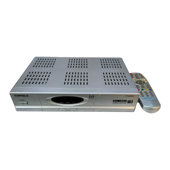
TOPFIELD
TF 4000 Fi
User Guide
Digital Satellite Receiver
Related Manuals for Topfield TF 4000 Fi
Summary of Contents for Topfield TF 4000 Fi
-
Page 1
TOPFIELD TF 4000 Fi User Guide Digital Satellite Receiver… -
Page 3: Table Of Contents
Contents Contents 1 Introduction Features ……. Controlling the digital receiver .
-
Page 4
iv CONTENTS 3.2.3 Sound mode ……15 3.2.4 Radio frequency output ….15 Local time setting . -
Page 5
7 Firmware Update Over the air ……44 From your computer via RS-232 port . -
Page 7: Introduction
Chapter 1 Introduction The TF 4000 Fi digital receiver is fully compliant with the in- ternational Digital Video Broadcasting (DVB) standard, and can receive digital broadcasts. For its operation, you need an antenna, which must be installed appropriately. NOTE In general we equate a channel with a frequency. However, unlike analog broadcasts, digital broadcasts are not all as- signed to their own frequencies;…
-
Page 8: Controlling The Digital Receiver
2 Introduction • Can store up to 5000 television and radio services. • Has an electronic program guide that provides an overview of program schedules for next few hours. • You can edit the service list. • You can make a favorite list with your favorite channels. •…
-
Page 9
1.2 Controlling the digital receiver 3 CHANNEL buttons move to the next or previous ser- vice. They are also used to navigate in the menus and interactive screens. STANDBY lamp lights up while the digital receiver is in standby mode. REMOTE lamp lights up whenever you press a button of the remote control. -
Page 10: The Remote Control
4 Introduction 1.2.2 The remote control button switches the digital re- ceiver between standby mode and operation mode. (On/Off) button mutes the sound. Press again to switch it back on. Numeric buttons are used to enter service numbers and menu options. button switches between the current service and the previously viewed one.
-
Page 11
1.2 Controlling the digital receiver 5 button displays the service list. It is also used to select menu items. button switches between television services and radio services. button displays the satellite list. buttons increase and decrease the volume. They are also used to change options for a menu item. buttons move to the next or previous service. -
Page 12: Setup
6 Setup Chapter 2 Setup 2.1 Unpacking Before going any further, check that you have received the fol- lowing items with your digital receiver. • Remote control unit • Two batteries for the remote control (AAA 1.5 V) • A copy of this user guide 2.2 Safety precautions Please read the following safety precautions carefully.
-
Page 13: Rear Panel Connections
9 W in standby Table 2.2: Physical specification Size 190 mm Weight 1.3 kg Operating temperature 0 to 45 °C Storage relative humidity 5 to 95 % 2.3 Rear panel connections The TF 4000 Fi has some connections on the back panel.
-
Page 14
8 Setup Check up what connections your television set has in compar- ison with the digital receiver. LNB IN Broadcasting input socket LNB OUT Broadcasting output socket through the LNB IN socket for another digital receiver. VIDEO Composite video output socket for the tele- vision set (Yellow) AUDIO L/R Stereo audio output socket for the television set or audio system. -
Page 15: Connecting Up Your Digital Receiver
2.4 Connecting up your digital receiver 9 2.4 Connecting up your digital receiver There are several ways to set up the digital receiver. Set up the digital receiver suitably to your television and other appli- ances. If you have any problem with your setup or need help, contact your dealer.
-
Page 16: Inserting Batteries In The Remote Control
10 Setup To use the composite video connector You will need to obtain a composite video cable (RCA cable) to use the composite video connector. Plug one end of the cable into the VIDEO (yellow) socket on the digital re- ceiver, and the other end into the matching socket on your television.
-
Page 17
2.4 Connecting up your digital receiver 11 larity, which is marked on the base of the battery compart- ment. If the digital receiver no longer reacts properly to remote con- trol commands, the batteries may be flat. Be sure to remove used batteries. -
Page 18: Preference Settings
12 Preference Settings Chapter 3 Preference Settings 3.1 Language settings You can designate languages for menus, audio tracks and sub- title tracks. Select the System Setting Language Setting menu. Menu language The digital receiver supports a lot of menu languages: Dutch, English, German, French, Italian, Russian, Turkish and so forth.
-
Page 19: Video And Audio Settings
3.2 Video and audio settings 13 lect a language, the menu will be immediately displayed in the selected language. Subtitle language Set the Subtitle Language option to your choice. When you watch a program, the subtitle track of the selected language will be output if available.
-
Page 20: Television Standard
14 Preference Settings 3.2.1 Television standard The digital receiver supports two types of television standard. One is the PAL standard, and the other is the NTSC stan- dard. PAL was adopted in European countries while NTSC is adopted in USA, Canada, Mexico and so forth. If you have a PAL television, you have to set the TV Type op- tion to PAL.
-
Page 21: Sound Mode
3.2 Video and audio settings 15 If you have a normal-screen television, set the TV Aspect Ratio option to 4:3. You cannot fully enjoy wide-screen programs with your normal- screen television as the above figures show. The left figure shows a normal picture displayed in the normal screen. To watch wide-screen programs in the shape like the center fig- ure, set the Display Format option to Letter Box.
-
Page 22: Local Time Setting
16 Preference Settings Table 3.1: Television standards by country Signal type Country PAL G Australia, Austria, Cyprus, Czech Republic, Egypt, Estonia, Finland, Ger- many, Greece, Iceland, Iran, Israel, Italy, Kuwait, Latvia, Libya, Lithuania, Luxembourg, Netherlands, New Zealand, Norway, Portugal, Slovakia, Slove- nia, Spain, Sweden, Switzerland, Syria, Yugoslavia PAL I Hong Kong, Macao, Republic of Ireland, South Africa, United Kingdom…
-
Page 23
3.3 Local time setting 17 wich Mean Time (GMT). However, it is recommended to use the auto setting. Table 3.2: Time offset table Time offset City 12:00 Eniwetok, Kwajalein 11:00 Midway Island, Samoa 10:00 Hawaii 09:00 Alaska 08:00 Pacific Time US, Canada 07:00 Mountain Time US, Canada 06:00… -
Page 24: Parental Control
18 Preference Settings 3. Make sure that your local time is correctly displayed on the Local Time option. To set the local time yourself, set the Mode option to Man- ual and enter your local time to the Local Time option with the numeric buttons.
-
Page 25: Adjusting The On-Screen Display
3.5 Adjusting the on-screen display 19 NOTE If a program does not have any rating information, your rating setting will not take effect. If anyone is trying to watch a program that is out of the ba- sis rating, the person has to enter the personal identification number to override.
-
Page 26: Service Search
20 Service Search Chapter 4 Service Search After connecting up the digital receiver, you will need to per- form a service search. 4.1 Searching broadcasting services This digital receiver can be operated with both fixed and mo- torized antenna system. You have to configure antenna set- tings according to your antenna system in the following order: 1.
-
Page 27
4.1 Searching broadcasting services 21 The LNB (Low Noise Block converter) is used to take a wide band of rel- atively high frequencies, amplify and convert them to similar signals carried at a much lower frequency, which is called IF (Intermediate Frequency). High frequencies from satellites are converted into from 950 to 2150 MHz by a LNB. -
Page 28: Configuring Diseqc 1.2 Settings
22 Service Search satellite list, you might have to make out the correct LNB fre- quency. The difference between a broadcasting frequency and its LNB frequency must be within 950 to 2150 MHz. For exam- ple, if the frequency band of your desired satellite ranges from 3660 to 4118 MHz, you have to set the LNB Frequency option to 5150 MHz.
-
Page 29
4.1 Searching broadcasting services 23 When you switch to an service, if the service is provided by a satellite other than current one, it will take longer time than usual because the antenna has to turn to its position. To use DiSEqC 1.2, select the In- stallation Motorized DiSEqC 1.2 menu. -
Page 30: Configuring Usals Settings
24 Service Search 5. Finally select the Store option at the Motor Control menu to save the tuned position when the receiving quality has turned good. There are more motor control options for installers, but this manual does not describe them. If you are an installer, refer them to the manual for the STAB rotor.
-
Page 31: Searching Services
4.1 Searching broadcasting services 25 4. Select the Goto the position option. Then the antenna will turn toward your selected satellite calculating its position. 5. If the receiving quality, which is displayed on the right bottom on the screen, is not good, then tune the antenna finely with the options of the Move menu.
-
Page 32
26 Service Search 2. Set the Search Mode option to Auto. To search every service of a transponder, perform the follow- ing steps: 1. Choose your desired satellite at the Satellite Name op- tion. 2. Set the Search Mode option to Manual. 3. -
Page 33: Editing The Transponder List
4.2 Editing the transponder list 27 To search every service of a SMATV transponder, if the digi- tal receiver is connected to a SMATV, perform the following steps: 1. Choose your desired satellite at the Satellite Name op- tion. 2. Set the Search Mode option to SMATV. 3.
-
Page 34: Resetting To Factory Settings
28 Service Search To edit the transponder list, se- lect the Installation SAT/TP Edit menu. To add a satellite entry, select the Add Satellite option. Then the on-screen keyboard appears. Enter your desired name and save it. For how to use the keyboard, refer to § 6.2. To change a satellite entry’s name, select your desired entry at the Satellite Name option and select the SAT Name Edit op- tion.
-
Page 35: Resetting To Installer Settings
4.4 Resetting to installer settings 29 • Satellite list • Service list • Favorite list • Timer list • Preference settings You can reset all data of the digital receiver. If you want to re- set all the data, select the Installation Factory Setting menu, then you are asked for confirmation.
-
Page 36: Daily Usage
30 Daily Usage Chapter 5 Daily Usage 5.1 Volume control Use the buttons to alter the volume to a comfortable level. You may need to adjust the volume on your television set too. To temporarily switch off the sound, press the but- ton.
-
Page 37: Watching Favorite Services
5.2 Watching television 31 On the service list, you can view the service information as fol- lows: • Service number • Service name • Transmitting satellite • Transponder information A dollar sign ($) may be marked on some entries, which in- dicates pay service.
-
Page 38: Viewing Program Information
32 Daily Usage To display the favorite list, press button; it will be dis- played. Whenever moving the highlight bar on or down on the favorite group list, favorite services belonging to the high- lighted group are listed. To select a favorite service, put the hightlight bar on a desired group and press the button;…
-
Page 39: Selecting Audio Tracks
5.2 Watching television 33 • Service number • Service name • Transmitting satellite • Transponder information • Signal level and quality • Program name • Program rating • Program summary • Broadcasting time • Current time In addition, you might see the following symbols: •…
-
Page 40: Selecting Subtitle Tracks
34 Daily Usage 5.2.4 Selecting subtitle tracks Some programs are provided with subtitle tracks in one or more languages. If the current program provides subtitle tracks, the subtitle symbol ( ) will be marked on the information box. Pressing the button displays available subtitle tracks.
-
Page 41: Watching Multifeed Program
5.4 Watching multifeed program 35 To see detailed information of a desired program, put the high- light bar on your choice with the button and press button. To switch to other service, press the button. To see the program guide for radio broadcasts, press the button.
-
Page 42: Making Timer Events
36 Daily Usage If a multifeed program is provided on the current service, the multifeed symbol ( ) will be marked on the information box. Press the button, then available video tracks will be listed. Once you select one, it will be presented. At this time, you have to press the button once more to select audio tracks.
-
Page 43
5.5 Making timer events 37 4. There are five timer modes: One Time means literally ‘one time’. Every Day means literally ‘every day’. Every Weekend means ‘Saturday and Sunday per week’. Weekly means ‘one day per week’. Every Weekday means ‘from Monday to Friday per week’. -
Page 44: Listing Services
38 Listing Services Chapter 6 Listing Services 6.1 Editing the service list You would have got the service list after service search. You can rename, move, lock or delete service entries on the service list. To edit the service list, select the Organizing Services menu;…
-
Page 45
6.1 Editing the service list 39 To edit the radio service list, press button; then radio service entries will be listed on the right column. To turn back to the television service list, press it again. To change the name of a service, select the Rename and select a desired service;… -
Page 46: Editing The Favorite List
40 Listing Services Sort A–Z by service name Sort CAS–FTA from pay services to free services Sort FTA–CAS from free services to pay services Sort Fav–NoFav from favorite services to unfavorite services. Sort Sat Name by satellite 6.2 Editing the favorite list You can make your own favorite service list.
-
Page 47
6.2 Editing the favorite list 41 You can up to 30 groups. To add a group, select the NEW option in the group list; then the on-screen keyboard appears. You can move the highlight key horizontally with the buttons and vertically with buttons. -
Page 48: Transferring Receiver Data
42 Listing Services 6.3 Transferring receiver data The digital receiver retains such data as follows: • Service list • Favorite list • Preference settings It is possible to transfer receiver data to your digital receiver from another same digital receiver connecting them with a RS- 232 cable.
-
Page 49: Firmware Update
However, a new firmware may be released to improve the digital receiver. You can get a latest firmware and an update utility from the Topfield web site, http://www.i-topfield. com. You should check the firmware information of your digital re- ceiver before downloading a new firmware.
-
Page 50: Over The Air
Horizontal update. This transponder information can be changed. You can get the information at the Topfield web site, http://www.i-topfield. com. 7.2 From your computer via RS-232 port It is possible to transfer a new firmware to the digital receiver from your computer connecting them with a RS-232 cable. You need TFD-Down, the firmware transfer utility for this, which…
-
Page 51: From Another Digital Receiver Via Rs-232 Port
7.3 From another digital receiver via RS-232 port 45 1. Download a new firmware applicable to the digital receiver from the Topfield web site. 2. Plug one end of a RS-232 cable (9 pin D- sub cable) into the RS-232 port on the digital receiver, and the other end into the matching port on your computer.
-
Page 52
46 Firmware Update 1. Plug one end of a RS-232 cable (9 pin D- sub cable) into the RS-232 port on the digital receiver, and the other end into the matching port on the other digital re- ceiver. 2. Turn on both of them. 3. -
Page 53: Index
Index 16:9, Delete Satellite, 22 kHz, Delete TP, 4:3, DiSEqC, DiSEqC 1.0, A/V Output Setting, DiSEqC 1.1, Access Control, DiSEqC Command Mode, Add new TP, Display Format, Add Satellite, Download, Advanced, Duration, Astra, DVB, AUDIO L, AUDIO L/R, Electronic Program Guide, Audio Language, electronic program guide, AUDIO R,…
-
Page 54
48 INDEX Goto, normal-screen television, Goto the position, NTSC, Info Box Display Time, on-screen keyboard, Info Box Position, One Time, information box, Organizing Favorites, IRD Status, Organizing Services, OSD Transparency, band, Other, Language Setting, PAL, Letter Box, Parental Control, LNB, PID, LNB Frequency, 21, PID,… -
Page 55
SMATV, Type, SMATV, USALS, Sort, USALS Setting, Sort A–Z, User, Sort CAS–FTA, Sort Fav–NoFav, VCR Timer Setting, Sort FTA–CAS, VIDEO, 8–10 Sort Sat Name, Sound Mode, Wakeup Time, Space, Weekly, Start, wide-screen television, Start Search, stereo, Stop, Store, 24, subtitle, Subtitle Language, Symbol Rate, 26, System ID,… -
Page 58
Correct disposal of this product This marking shown on the product or its literature indicates that it should not be disposed with other household wastes at the end of its working life. To prevent possible harm to the environment or human health from uncon- trolled waste disposal, please separate this from other types of wastes and recycle it responsibly to promote the sustainable reuse of material resources.
Посмотреть инструкция для Topfield TF 4000 Fi бесплатно. Руководство относится к категории приемники, 1 человек(а) дали ему среднюю оценку 7.5. Руководство доступно на следующих языках: английский. У вас есть вопрос о Topfield TF 4000 Fi или вам нужна помощь? Задайте свой вопрос здесь
Не можете найти ответ на свой вопрос в руководстве? Вы можете найти ответ на свой вопрос ниже, в разделе часто задаваемых вопросов о Topfield TF 4000 Fi.
Когда звук считается слишком громким?
Могут ли устройства разных марок подключаться друг к другу при помощи Bluetooth?
Как лучше всего выполнять чистку приемник?
Инструкция Topfield TF 4000 Fi доступно в русский?
Не нашли свой вопрос? Задайте свой вопрос здесь
- Manuals
- Brands
- Topfield Manuals
- Receiver
- TF4000FI
- Service manual
-
Contents
-
Table of Contents
-
Bookmarks
Quick Links
TF4000Fi
Service Manual
15 March, 2004
Topfield Co., Ltd
Related Manuals for Topfield TF4000FI
Summary of Contents for Topfield TF4000FI
-
Page 1: Service Manual
TF4000Fi Service Manual 15 March, 2004 Topfield Co., Ltd…
-
Page 2: Important
IMPORTANT Note : The design of the satellite receiver is subject to continuous development and improvement. Consequently, this receiver may incorporate minor changes in detail from the information contained in this manual. Warning : These servicing instructions are for use by qualified personnel only. To reduce the risk of electric shock, do not perform any servicing other than that specified in the operating instructions unless you are fully qualified to do so.
-
Page 3: Table Of Contents
TABLE OF CONTENTS Page IMPORTANT …………………. 2 1. Safety Instructions ………………5 2. List and Description of The Major Parts …………6 2.1. Main Board ………………….6 2.2. Front Board ………………….6 3. Block Diagram of The IRD …………….7 4.
-
Page 4
5.5.2. Test the diodes……………………..17 5.5.3. Check the Shunt regulator ………………….17 5.5.4. Check the Pothocoupler IC………………….17 5.5.5. Check the Fuse……………………… 17 6. PIN description of The Major Parts …………18 6.1. Main Board ………………….18 6.2. Front Board ………………….18 6.3. -
Page 5: Safety Instructions
1. Safety Instructions Read this chapter carefully before servicing the IRD. 1.1 The IRD must be disconnected from the mains plug before it is opened. 1.2 The capacitor inside the SMPS (power supply) can hold charge even if the IRD has been disconnected from the mains plug.
-
Page 6: List And Description Of The Major Parts
List and Description of The Major Parts 2.1. Main Board Part Location Part number Function Comment Name Number Tuner module TBMU24311IPP Channel tuning. Or, equivalent part Analog to Digital Conversion. QPSK demodulation. Regulator LM7805 Regulates Tuner 5V Or, equivalent part (with Heat Sink) LNB Power LNBP20PD…
-
Page 7: Block Diagram Of The Ird
3. Block Diagram of The IRD…
-
Page 8: Block Diagram Of The Main Board
4. Block Diagram of The Main Board…
-
Page 9: Test And Repair
5. Test and Repair 5.1. Visual Test — Check whether all the connectors are plugged well. ‘JP4’ of Main Board : power connector. ‘JP5’ of Main Board : connector for Front Board interface ‘JP3’ of Main Board : Connector for SMART Card sub-Board interface (optional). — Check whether the SMPS(power supply) has any damage.
-
Page 10: Basic Function Test
5.2. Basic Function Test 5.2.1. No LED is turned on Possible Cause How to Check How to repair Front Board Problem Replace the Front Board with If it works, repair the Front Board. new one which works well in the Otherwise, check the Main Board other IRD and SMPS.
-
Page 11: No Picture But The Osd Works
5.2.6. No picture but the OSD works. Possible Cause How to Check How to repair Tuner problem If the signal level of the tuner is Check the antenna signal. very low, it may be a problem of Check the tuner part. the tuner, antenna cable or antenna.
-
Page 12: No Sound And/Or No Picture On The Rf Modulator (Cinch Works Well)
5.2.10. No sound and/or no picture on the RF modulator (Cinch works well) Possible Cause How to Check How to repair RF channel is selected Check channel Select the correct channel. incorrectly. selection. modulator Replace the RF modulator with Replace it with new one. problem.
-
Page 13: The Advanced Test Of Main Board
5.3. The Advanced Test of Main Board. 5.3.1. Voltages on important point — Voltage at JP4 in page 8 (of schematic diagram) Minimum Nominal Maximum Comment number voltage voltage voltage +28V +30V +32V +20V +22V +23V +16V +17V +18V +7.6V +8.4V not used not used…
-
Page 14: System Clock
Schematic page 4. 5.3.3. System Clock Schematic page 3 VCXO1 generates the system clock. The ‘SCLK’ signal is 27.000MHz clock signal . If the color of the picture disappear , the ‘SCLK’ signal may be different from 27.000MHz or the VCXO1 have bad quality.
-
Page 15: Lnb Power
nothing happens in the receiver, check the download cable and the PC. The pin2 and pin3 of the download cable should be crossed. — Check point 1 — Check the download cable and the PC with a new receiver. — Check point 2 — Check the error code on the display of the Front Board.
-
Page 16: Rf Modulator
Set the LNB voltage to Horizontal — Check Point – Check level of U3.5 whether logically ‘HIGH’ ( about 3V ). If logically ‘LOW’ ( about 0V) then check the line from U5 (IBM39STB02500 ) and U3.5. Check level of U3.6 whether logically ‘HIGH’ ( about 3V ). If logically ‘LOW’ ( about 0V) then check the line from U5 (IBM39STB02500) and U3.6.
-
Page 17: The Advanced Test Of Smps
5.5. The Advanced Test of SMPS. Caution ————————————— ——————————————- I. The SMPS must be disconnected from the mains plug to test. II. The capacitor inside the SMPS (power supply) can hold charge even if the IRD has been disconnected from the mains plug. To handle SMPS, wait until the capacitor is discharged.
-
Page 18: Pin Description Of The Major Parts
6. PIN description of The Major Parts 6.1. Main Board Tuner Module TBMU24311IPP Regulator LM7805 LNB Power Switching IC LNBP20PD CPU, Demux and Decoder IBM39STB02500 Flash Memory SST39VF800A EEPROM 24LC02B-SN SDRAM K4S641632D Reset IC ELM9727NBA Regulator LD1117ADT18 Regulator MIC39100-2.5BS Regulator 78L12 RS232 Driver MAX232…
-
Page 20: General Description
February 1995 LM78XX Series Voltage Regulators General Description The LM78XX series of three terminal regulators is available of external components It is not necessary to bypass the with several fixed output voltages making them useful in a output although this does improve transient response Input wide range of applications One of these is local on card bypassing is needed only if the regulator is located far from regulation eliminating the distribution problems associated…
-
Page 21
LNBP10 SERIES — LNBP20 input pin is available (EXTM). An appropriate DC IMPEDANCE. If the overload is still present, the blocking capacitor must be used to couple the protection circuit will cycle again through t modulating signal source to the EXTM pin. When ton until the overload is removed. -
Page 22
IBM39STBx25xx Preliminary STBx25xx Digital Set-Top Box Integrated Controllers 1.6.4.10 Real Time Clock / Front Panel Controller The Real Time Clock (RTC) counts seconds, minutes, hours, and days. Programmable alarms can be set to interrupt the CPU, allowing the CPU to wake up when required to perform functions such as programming a VCR. -
Page 23
IBM39STBx25xx STBx25xx Digital Set-Top Box Integrated Controllers Preliminary Table 1-1. Signals Sorted by Signal Name I/O Signal Name Ball Number BI_CS0 BI_CS1 BI_CS2 BI_CS3 BI_DATA0 BI_DATA1 BI_DATA10 BI_DATA11 BI_DATA12 BI_DATA13 BI_DATA14 BI_DATA15 BI_DATA2 BI_DATA3 BI_DATA4 BI_DATA5 BI_DATA6 BI_DATA7 BI_DATA8 BI_DATA9 BI_OE BI_READY BI_RW… -
Page 24
IBM39STBx25xx Preliminary STBx25xx Digital Set-Top Box Integrated Controllers Table 1-1. Signals Sorted by Signal Name I/O Signal Name Ball Number DAC1_AGND1 DAC1_AGND2 DAC1_AVDD0 DAC1_AVDD1 DAC1_AVDD2 DAC1_AVDD3 DAC1_VOUT1 DAC1_CREF_OUT DAC1_VOUT2 DAC1_GREF_OUT DAC1_VOUT3 DAC1_RREF_OUT DAC1_VREF_IN DAC2_AGND0 DAC2_AGND1 DAC2_AGND2 DAC2_AVDD0 DAC2_AVDD1 DAC2_AVDD2 DAC2_AVDD3 DAC2_VOUT1 DAC2_CREF_OUT DAC2_VOUT2… -
Page 25
IBM39STBx25xx STBx25xx Digital Set-Top Box Integrated Controllers Preliminary Table 1-1. Signals Sorted by Signal Name I/O Signal Name Ball Number AA21 AA23 Product Overview Stbx25_Overview.fm.02 Page 46 of 890 May 31, 2002- IBM Confidential… -
Page 26
IBM39STBx25xx Preliminary STBx25xx Digital Set-Top Box Integrated Controllers Table 1-1. Signals Sorted by Signal Name I/O Signal Name Ball Number AB22 AC10 AC14 AC18 AC23 GPIO0 GPIO1 GPIO10 GPIO11 GPIO12 GPIO13 GPIO14 GPIO15 GPIO16 GPIO17 GPIO18 GPIO19 GPIO2 GPIO20 GPIO21 GPIO22 GPIO23 GPIO24… -
Page 27
IBM39STBx25xx STBx25xx Digital Set-Top Box Integrated Controllers Preliminary Table 1-1. Signals Sorted by Signal Name I/O Signal Name Ball Number I2C0_SCL I2C0_SDA INT0 INT1 INT2 RW_HALT RW_TCK RW_TDI RW_TDO RW_TMS RW_TRST SC0_CLK SC0_DETECT SC0_IO SC0_RESET SC0_VCC SC1_CLK SC1_DETECT SC1_IO SC1_RESET SC1_VCC SD0_ADDRESS0 SD0_ADDRESS1… -
Page 28
IBM39STBx25xx Preliminary STBx25xx Digital Set-Top Box Integrated Controllers Table 1-1. Signals Sorted by Signal Name I/O Signal Name Ball Number SD0_CLK SD0_CS0 SD0_DATA0 SD0_DATA1 SD0_DATA10 SD0_DATA11 SD0_DATA12 SD0_DATA13 SD0_DATA14 SD0_DATA15 SD0_DATA2 SD0_DATA3 SD0_DATA4 SD0_DATA5 SD0_DATA6 SD0_DATA7 SD0_DATA8 SD0_DATA9 SD0_DQMH SD0_DQML SD0_RAS SD0_WE SD1_ADDRESS0… -
Page 29
IBM39STBx25xx STBx25xx Digital Set-Top Box Integrated Controllers Preliminary Table 1-1. Signals Sorted by Signal Name I/O Signal Name Ball Number SD1_CAS AA16 SD1_CLK AA15 SD1_CS0 AC15 SD1_DATA0 SD1_DATA1 SD1_DATA10 AC13 SD1_DATA11 AB13 SD1_DATA12 AA13 SD1_DATA13 AB14 SD1_DATA14 AA14 SD1_DATA15 SD1_DATA2 SD1_DATA3 SD1_DATA4 AA10… -
Page 30
IBM39STBx25xx Preliminary STBx25xx Digital Set-Top Box Integrated Controllers Table 1-1. Signals Sorted by Signal Name I/O Signal Name Ball Number VDD2 VDD2 VDD2 VDD2 VDD2 VDD2 VDD2 VDD2 VDD2 VDD2 VDD2 VDD2 VDD2 VDD2 VDD2 VDD2 Stbx25_Overview.fm.02 Product Overview May 31, 2002- IBM Confidential Page 51 of 890… -
Page 31
IBM39STBx25xx Preliminary STBx25xx Digital Set-Top Box Integrated Controllers 1.10 Mechanical Information Package Diagram Top of Package (BGA Side Down) IBM P/N XXXXXXX ZZWWMMMM Date Code IBM39 STBx25xx xxx xxx 0.25 OEM P/N 1.22 15.5 0.15 .610 27.94 1.27 .050 E52P SUBSTRATE GLOB Cavity… -
Page 32
2 Mbit / 4 Mbit / 8 Mbit Multi-Purpose Flash SST39LF200A / SST39LF400A / SST39LF800A SST39VF200A / SST39VF400A / SST39VF800A Data Sheet UNCTIONAL LOCK IAGRAM SuperFlash X-Decoder Memory Memory Address Address Buffer & Latches Y-Decoder I/O Buffers and Data Latches Control Logic DQ 15 — DQ 0 360 ILL B1.2… -
Page 33
Features • Low-Voltage and Standard-Voltage Operation – 5.0 (V = 4.5V to 5.5V) – 2.7 (V = 2.7V to 5.5V) – 2.5 (V = 2.5V to 5.5V) – 1.8 (V = 1.8V to 5.5V) • Internally Organized 128 x 8 (1K), 256 x 8 (2K), 512 x 8 (4K), 1024 x 8 (8K) or 2048 x 8 (16K) •… -
Page 34
K4S641632D CMOS SDRAM PIN CONFIGURATION (Top view) DQ15 DQ14 DQ13 DQ12 DQ11 DQ10 LDQM N.C/RFU UDQM A10/AP 54Pin TSOP (II) (400mil x 875mil) (0.8 mm Pin pitch) PIN FUNCTION DESCRIPTION Name Input Function System clock Active on the positive going edge to sample all inputs. Disables or enables device operation by masking or enabling all inputs except Chip select CLK, CKE and L(U)DQM… -
Page 36
LD1117 SERIES CONNECTION DIAGRAM (top view) SOT-223 SO-8 TO-220FM TO-220 DPAK NOTE: The TAB is connected to the V ORDERING CODES OUTPUT SOT-223 SO-8 DPAK TO-220 TO-220FM VOLTAGE LD1117S12 LD1117D12 (*) LD1117DT12 LD1117V12 (*) LD1117F12 (*) 1.2 V LD1117S18 LD1117D18 LD1117DT18 LD1117V18 LD1117F18… -
Page 37: Pin Description
MIC39100/39101/39102 Micrel Pin Configuration MIC39100-x.x Fixed SOT-223 (S) 8 GND 8 GND MIC39101-x.x MIC39102 Fixed Adjustable SOP-8 (M) SOP-8 (M) Pin Description Pin No. Pin No. Pin No. Pin Name Pin Function MIC39100 MIC39101 MIC39102 Enable (Input): CMOS-compatible control input. Logic high = enable, logic low or open = shutdown.
-
Page 38
L78L00 CONNECTION DIAGRAM AND ORDERING NUMBERS (top view) pin 1 = V pin 2 = GND pin 3 = V SO-8 SOT-89 TO-92 BOTTOM VIEW ORDERING NUMBERS Type SO-8 TO-92 SOT-89 (T&R) Output Voltage L78L33AC L78L33ACD L78L33ACZ L78L33ACUTR 3.3 V L78L33AB L78L33ABD L78L33ABZ… -
Page 39
+5V-Powered, Multichannel RS-232 Drivers/Receivers +5V INPUT TOP VIEW 2 +10V +5V TO +10V VOLTAGE DOUBLER -10V +10V TO -10V VOLTAGE INVERTER MAX220 MAX232 400k MAX232A TTL/CMOS RS-232 INPUTS 400k OUTPUTS DIP/SO R1 I TTL/CMOS RS-232 CAPACITANCE (µF) OUTPUTS INPUTS DEVICE MAX220 MAX232 MAX232A… -
Page 40
Philips Semiconductors Preliminary specification Low power audio DAC UDA1334TS PINNING SYMBOL PAD TYPE DESCRIPTION 5 V tolerant digital input pad; note 1 bit clock input 5 V tolerant digital input pad; note 1 word select input DATAI 5 V tolerant digital input pad; note 1 serial data input digital supply pad digital supply voltage… -
Page 42: Block Diagram
TSOP48..SB1 Vishay Telefunken Photo Modules for PCM Remote Control Systems Available types for different carrier frequencies Type Type TSOP4830SB1 30 kHz TSOP4833SB1 33 kHz TSOP4836SB1 36 kHz TSOP4837SB1 36.7 kHz TSOP4838SB1 38 kHz TSOP4840SB1 40 kHz TSOP4856SB1 56 kHz Description The TSOP48..SB1 –…
-
Page 43
TSOP48..SB1 Vishay Telefunken Dimensions in mm 16777 www.vishay.com Document Number 82108 6 (7) Rev. 6, 29-Mar-01… -
Page 44
www.fairchildsemi.com KA1L0380B/KA1L0380RB/ KA1M0380RB/KA1H0380RB Fairchild Power Switch(FPS) Features Description • Precision fixed operating frequency The Fairchild Power Switch(FPS) product family is specially • (50KHz) designed for an off line SMPS with minimal external KA1L0380B/KA1L0380RB • (67KHz) components. The Fairchild Power Switch(FPS) consist of high KA1M0380RB •… -
Page 45
www.fairchildsemi.com KA431/KA431A/KA431L Programmable Shunt Regulator Features Description • Programmable output voltage to 36 volts The KA431/KA431A/KA431L are three-terminal adjustable • Low dynamic output impedance 0.20 typical regulator series with a guaranteed thermal stability over • Sink current capability of 1.0 to 100mA applicable temperature ranges. -
Page 46: Schematic Diagrams
7. Schematic Diagrams 7.1. Schematic diagram of Front Board — see next page.
-
Page 48: Schematic Diagram Of Main Board
7.2. Schematic diagram of Main Board — see next page. -…
-
Page 61: Schematic Diagram Of Smps (Power Supply)
7.3. Schematic diagram of SMPS (power supply) — see next page. -…
- Home
- Brands
- Topfield Manuals
- Receiver
- TF 4000 Fi
|
|
Related Devices:
|
Types of Manuals:
The main types of Topfield TF 4000 Fi instructions:
- User guide — rules of useing and characteristics
- Service manual — repair, diagnostics, maintenance
- Operation manual — description of the main functions of equipment
Receiver, Satellite TV System User Guides by Topfield:
Similar to Topfield TF 4000 Fi Manuals, User Guides and Instructions:
-
JVC RX-DV31SL
JVCHOME THEATER DVD-AUDIONIDEO RECEIVERRX-DV31StAI/f_I’_UD/I I IA//fAUD=OIVmEOTMDIGITALDIGITALSURROUNDJ@@3©©©©©©©3©©©000_ czJcz_cz_INSTRUCTIONSFor Customer Use:Enter below the Model No. and SerialNo. which are located either on the rear,bottom or side of the cabinet, Retain thisinformation for future ref …
RX-DV31SL Receiver, 78
-
Telonics TR-8
1 of 2 2021.05.05 Telonics TR-8 Quick Start Guide Visit www.telonics.com/products/vhfReceivers/tr-8.php for the complete TR-8 User Manual. Power On/Off Press and hold the power button for a full second to turn the TR-8 on or off. If the TR-8 won’t turn on, and if the red LED comes on instead, charge the battery. Ba …
TR-8 Receiver, 2
-
Pioneer VSX-AX4ASi-S
VSX-AX4ASi-SVSX-AX2AS-SAUDIO/VIDEO MULTI-CHANNEL RECEIVEROperating InstructionsDiscover the benefits of registering your product online at www.pioneer.co.uk (www.pioneer-eur.com).VSX_AX4ASi.book.fm 1 ページ 2006年4月11日 火曜日 午後4時19分 …
VSX-AX4ASi-S Receiver, 92
-
Harman Kardon AVR45
harman/kardon AVR45 A/V DOLBY DIGITAL RECEIVER SERVICE MANUAL CONTENTS ELECTROSTATICALLY SENSITIVE(ES)DEVICES..…2 LEAKAGE TEST……………………….…………………. 3 SPECIFICATIONS…………………………………………4 CONTROLS AND FUNCTIONS………………………….6 REAR PANEL …
AVR45 Receiver, 87
Устройство:
Topfield TF 4000
Размер: 2,12 MB
Добавлено: 2013-11-04 13:56:52
Количество страниц: 100
Печатать инструкцию
Скачать
Как пользоваться?
Наша цель — обеспечить Вам самый быстрый доступ к руководству по эксплуатации устройства Topfield TF 4000. Пользуясь просмотром онлайн Вы можете быстро просмотреть содержание и перейти на страницу, на которой найдете решение своей проблемы с Topfield TF 4000.
Для Вашего удобства
Если просмотр руководства Topfield TF 4000 непосредственно на этой странице для Вас неудобен, Вы можете воспользоваться двумя возможными решениями:
- Полноэкранный просмотр -, Чтобы удобно просматривать инструкцию (без скачивания на компьютер) Вы можете использовать режим полноэкранного просмотра. Чтобы запустить просмотр инструкции Topfield TF 4000 на полном экране, используйте кнопку Полный экран.
- Скачивание на компьютер — Вы можете также скачать инструкцию Topfield TF 4000 на свой компьютер и сохранить ее в своем архиве. Если ты все же не хотите занимать место на своем устройстве, Вы всегда можете скачать ее из ManualsBase.
Topfield TF 4000 Руководство по эксплуатации
Печатная версия
Многие предпочитают читать документы не на экране, а в печатной версии. Опция распечатки инструкции также предусмотрена и Вы можете воспользоваться ею нажав на ссылку, находящуюся выше — Печатать инструкцию. Вам не обязательно печатать всю инструкцию Topfield TF 4000 а только некоторые страницы. Берегите бумагу.
Резюме
Ниже Вы найдете заявки которые находятся на очередных страницах инструкции для Topfield TF 4000. Если Вы хотите быстро просмотреть содержимое страниц, которые находятся на очередных страницах инструкции, Вы воспользоваться ими.