
-
Contents
-
Table of Contents
-
Bookmarks
Quick Links
MARINE DSC VHF RADIO TELEPHONE
FOR GMDSS
OPERATING MANUAL
STR- 6000A
SAMYUNGENC CO.,LTD.
Related Manuals for Samyung STR-6000A
Summary of Contents for Samyung STR-6000A
-
Page 1
MARINE DSC VHF RADIO TELEPHONE FOR GMDSS OPERATING MANUAL STR- 6000A SAMYUNGENC CO.,LTD. -
Page 2
When Distress Call is received, it is necessary to inform a person on duty about this. 2. How to make the initial set-up in installation For the below items, the initial set-up should be made in installation before its actual operation. Please contact SAMYUNG ENC or any agent dealers for the information. -
Page 3
2-1 How to check out power supply Input voltage in VHF main unit: Confirm that DC13.6V is supplied. 2-2 How to transmit and receive DSC In order to use DSC function, make sure that any MMSI number available must be input first. -
Page 4: Table Of Contents
……………………….10 3.1. STR-6000A Standards…………..10 3.2. Transmitting Unit …………….10 3.3. Receiving Unit …………….11 3.4. Dedicated Receiving Unit …………… 11 Chapter 4. How to Operation Chapter 4. How to Operation …….. Chapter 4. How to Operation Chapter 4.
-
Page 5
4.4.3.4. LCD BACKLIGHT …………26 4.4.3.5. LCD CONTRAST …………26 4.4.3.6. GPS FUNCTION SET …………. 26 4.4.3.7. MANUAL GPS/TIME…………27 4.4.3.8. DSC SET …………..27 4.4.3.9. RADIO SET …………..28 4.4.3.10. REAL TIME CLOCK(Current time change)……28 4.4.3.11. FACTORY RESET(MENU SETUP INITIALIZATION) ….. 28 4.4.3.12. -
Page 6
5.2. Selection of Installation Position for Main Units of STR-6000A …. 50 5.3. Installation for main unit of STR-6000A……….50 5.4. Cabling ………………52 5.4.1. Power Connection …………..53 5.4.2. Connects to External Speaker ……….53 5.4.3. How to setup Antenna …………53 5.4.4. -
Page 7: Chapter 1. Introduction
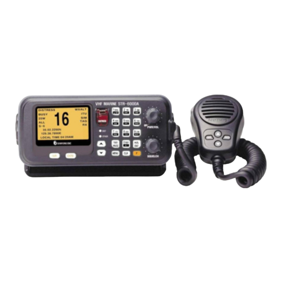
Chapter 1. Introduction 1.1. Introduction STR-6000A includes DSC/VHF radio telephone and DSC receiver required by the Global Maritime Distress and Safety System(GMDSS) and is designed to be compact and lightweight for easy installation in any vessels engaged in international voyages and near-going vessels.
-
Page 8
Such functions as TAG CHANNEL SCANNING, ALL CHANNEL SCANNING, GROUP-CHANNEL SCANNING and DUAL WATCH allow user to listen to any specific channel. Besides the existing voice communications, it is available to work on communications for distress, urgency, safety and other routines as well by using DSC function. In case that the coast station is working on automatic connection service of public communications network, it is available to auto-connect the general telephone through the designation of the telephone number on the equipment. -
Page 9: Chapter 2. Configuration
Chapter 2. Configuration The equipment consists of as follows; 2.1. Standards Name Model Quantity Remarks VHF Radio Main Unit STR-6000A 1 Set Including HAND MIC Manual STR-6000A-ME 1 Lot M02-0031-00 2.2. Option Name Model Remarks Including SAN-150 (RX/TX) 3dBi CABLE/BRACKET…
-
Page 10: Chapter 3. Specifications
Chapter 3. Specifications 3.1. STR-6000A Standards TX Frequency 156.025MHz ~ 157.425MHz RX Frequency 156.050MHz ~ 163.275MHz ITU Channel: 55 Number of Channels USA Channel: 53 CANADA Channel: 60 WEATHER Channel: 10 Radio Wave Mode FM(16K0G3E), DSC(16K0G2B) Channel Interval 25kHz Communication Mode…
-
Page 11: Receiving Unit
3.3. Receiving Unit Receive System Double Conversation Super Heterodyne 1st 21.7MHz Intermediate Frequencies 2nd 450kHz Local Oscillation Frequency Receiving Frequency — 21.7MHz Local Oscillation Mode SYNTHESIZER Mode 0.32uV (20dB SINAD) Sensitivity 0.22uV (12dB SINAD) Audio Frequency Response -6dB/octave Squelch Sensitivity 0.22uV Co-Channel Rejection -10dB ~ 0dB…
-
Page 12: Chapter 4. How To Operation
Chapter 4. How to Operation 4.1. Unit Description 4.1.1. Front Panel ① LCD Front Display Screen. Transmit distress call (Alert) MESSAGE. (※ You MUST NOT make a test of the transmission !! ) ② Push and hold down for 3 seconds, then the distress call will be activated.
-
Page 13
Short time press is for DSC Calling and long time press is for ⑧ MENU function. ⑨ This is ‘ESCAPE’ function in MENU mode. ⑩ It means this is being used as FUNCTION button. ⑪ PWR/VOL (Power Knob) Power ON/OFF and Volume Control. ⑫… -
Page 14
⑬ Button description Input “1” when selects CH and inputs digit. When used this button, it works ON/OFF for dual watch function. (It receives the message by switching over between the existing CH and CH16 each other continuously.) When inputs character, convert from 1→ space → Q →to Z in order and ENT. -
Page 15
When selects CH and inputs digit, input “6”. When used this button, it can set up TAG at selected CH. When inputs character, convert from 6 → M → N → to O in order and When selects CH and inputs digit, input “7”. When used this button, it can set up to ITU MODE.. -
Page 16: Microphone
4.1.2. Microphone ① PTT : If pressed, it goes to transmission. ② MIC : Condenser Mic ③ Key Pad : : To convert to the current CH and CH16. : It is used as Enter button for setting-up input data in MENU mode, while at normal times it is used for switching-over Tx power between 25W and 1W.
-
Page 17
Handmic Handmic Box… -
Page 18: Lcd Screen Description
4.2. LCD Screen Description Item Function Description DISTRESS CH Name BUSY It represents detecting the sensitivity signal in existing CH.. 25W(01W) It represents Tx Power. It represents the kinds of SCAN. It plays multi-scan between the existing CH and CH16. (It will be converted when scanning.) It indicates own ship’s latitude.
-
Page 19: Vhf Operation
4.3. VHF Operation 4.3.1. Channel Selection 4.3.1.1. Channel 16 CH.16 is for distress and safety, and it should be monitored through dual-watch and tri-watch. Whenever selected key, it shifted from the current CH → CH 16 → CH 9 → current CH.
-
Page 20: Weather Channel
4.3.2. Weather Channel It can receive 10 numbers of weather channel provided by NOAA (National Oceanographic and Atmospheric Administration). STR-6000A can detect the alert sound of selected weather channel from the regular channel or the one during the channel scanning When selected it converts between weather channel and general channel.
-
Page 21
(STR-6000A Main Body) (STR-6000A Microphone) -
Page 22: Menu Setup And Construction
4.4. Menu Setup and Construction 4.4.1. Menu Construction 1. FRIENDS MMSI LIST 2. GROUP MMSI LIST 3. TELEPHONE LIST 4. LCD BACKLIGHT 5. LCD CONTRAST GPS TIME OFFSET TIME DISPLAY FORMAT TIME DISPLAY ON/OFF 6. GPS FUNCTION SET LL DISPLAY ON/OFF GPS ALERT ON/OFF 7.
-
Page 23
Menu Select 1. DISTRESS CALL 2. ALL SHIP CALL Press MENU 3. INDIVIDUAL CALL button shortly 4. AUTO/SEMI CALL — CALL ITEM SELECT— 5. TEST CALL 6. GROUP CALL 7. POSITION POLL 8. DISTRESS RELAY 9. DISTRESS RLY ACK 10. DISTRESS ACK 11. -
Page 24: Menu Screen Construction And Initialization
4.4.2. Menu Screen Construction and Initialization Press button over one (1) second to get into the various Menu. 1. FRIENDS MMSI LIST ADD NEW FRIEND Friend ID register 2. GROUP MMSI LIST ADD NEW GROUP Group ID register 3. TELEPHONE LIST ADD NEW TELEPHONE Call ID register 4.
-
Page 25: Menu Setup
4.4.3. Menu Setup Press button at greater length. Overall construction of MENU Screen is as follows. Item Selection : From above screen, shift the cursor by using button and press button to select the current item. 4.4.3.1. FRIENDS MMSI LIST It can add/edit/delete the preferred friend’s name and associated MMSI up to 20 numbers.
-
Page 26: Telephone List
4.4.3.3. TELEPHONE LIST It can add/edit/delete the preferred Telephone name and associated MMSI up to 10 numbers. (It can save maximum 10 numbers) To add name to TELEPHONE To edit TELEPHONE To delete TELEPHONE 4.4.3.4. LCD BACKLIGHT Set-up backlight level to adjust the brightness of LCD and Key Pad. 4.4.3.5.
-
Page 27: Manual Gps/Time
4.4.3.7. MANUAL GPS/TIME LAT/LONG MANUAL SET(Input position manually) : Ship’s position and longitude is displayed on screen together with time. To display “MANUAL SETUP”, value of latitude, longitude and time will be displayed in reverse status. This display mode will be cancelled as soon as GPS receiver is connected and come to display normal mode.
-
Page 28: Radio Set
DSC FUNCTION DISABLE Set Up DSC function use. MEDI/SHIP_AIRCRAFT ON/OFF MEDIcal Transponder & SHIP and AIRCRAFT use. 4.4.3.9. RADIO SET CHANNEL NAME (CH NAME) Channel name modification and deletion. CHANNEL ON/OFF(CH ON/OFF) It is used for either permitting or stopping the use of current CH. WEATHER ALERT(Weather Alarm Setup) NOAA provides with a variety weather information regarding USA or CAN channel.
-
Page 29: Print Setup(Print Setup)
3 seconds in order to check button condition. PLL TEST (Test PLL condition on Tx and Rx) : It will be tested from minimum frequency to the maximum by 25KHz step. DISPLAY DEVIATION : LCD test (Display the character). SOUND TEST : Test on Bell, Emergency, Error and Alarm. SUB CPU Version : SUB CPU version check.
-
Page 30
navigational equipment, the data on time and position will be automatically input. It is available to manually input the time when the position data and position are decided. If the transmission is made when it is not connected with any navigational equipment or under the conditions where any single manual input has not been made, it will transmit zero information. -
Page 31: Configuration Of Call Screen
4.5.1. Configuration of CALL Screen Press button in short. The whole display configuration of DSC CALL MENU is as follows; Item selection : Use buttons in the above Screen and move to the wanted item and press button. 4.5.2. CALL Menu Description and Instruction 1.
-
Page 32: Distress Call(Distress Message Setup And Call)
4.5.2.1. DISTRESS CALL(Distress message SETUP and Call) On screen of CALL ITEM SELECT, select 1.DISTRESS CALL by using buttons and then press button. In order to select types of distress (Nature of Distress), select > NATURE : UNDEFINE list and then press button.
-
Page 33
In order to input distress position (POSITION), select >LAT / > LONG list by using buttons and then press button. It makes cursor blink and then input wanted longitude/latitude on the blinking cursor. After select TIME-UTC buttons and then press button. -
Page 34: All Ships Message Setup And Call
4.5.2.2. ALL SHIPS MESSAGE SETUP AND CALL Select 2.ALL SHIP CALL list on CALL ITEM SELECT screen by using buttons and then press button. ‘CATEGORY’ list is a function for selecting SAFETY or URGENCY, either and press button after move the cursor to > CATEGORY list by using buttons.
-
Page 35: Individual Message Setup And Call
After going through the edition of MESSAGE, select > TRANSMIT DSC list and transmit by suing buttons. 4.5.2.3. INDIVIDUAL MESSAGE SETUP AND CALL Press button after select 3. INDIVIDUAL CALL list on CALL ITEM SELECT screen by using buttons. It makes following screens. Press button after select >…
-
Page 36
By using button, select and press > CATEGORY button then following small screen shown up. Here on the item where the cursor is flickering, by using button and press button. By using button, select > TELECMD1 and press button then following small screen comes up and again press button. -
Page 37: Auto/Semi-Auto Message Edit And Call
button to send out message one time. 4.5.2.4. AUTO/SEMI-AUTO Message Edit and Call This function as an option will be further realized soon. 4.5.2.5. TEST CALL This function is used for testing call, following procedure in editing and calling for position messages shall be done. On CALL ITEM SELECT screen, by using button, select 5.
-
Page 38: Group Messsage Edit And Call
After finishing the edition of MESSAGE, press key at > TRANSMIT DSC then MESSAGE will be transmitted one time. 4.5.2.6. GROUP MESSSAGE EDIT AND CALL On CALL ITEM SELECT screen, select the item 6. GROUP CALL by using button, and press button.
-
Page 39: Position Message Edit And Call
Note : Currently using CH such as CH70, CH75, CH76 shall not be set-up. After finishing message edit, select > TRANSMIT DSC item by using button and send out the message. 4.5.2.7. POSITION MESSAGE EDIT AND CALL On CALL ITEM SELECT screen, select item 7. POSITION CALL by using button and press button.
-
Page 40: Distress Call Relay
After finishing the message edit, select the item > TRANSMIT DSC by using button and send-out message. 4.5.2.8. DISTRESS CALL RELAY Select item8. DISTRESS RELAY on CALL ITEM SELECT screen by using button and press button. After select > FORMAT using button and press button then following small screen comes up.
-
Page 41
Select > ADDRESS(MMSI) using button and press button then following screen comes up. From this screen, select the appropriate item by using button and press button. Select > TRANSMIT DSC by using button and press button then following screen comes up. From this screen, select YES or NO for sending Message by using button and press button. -
Page 42: Distress Relay Acknowledgement
4.5.2.9. DISTRESS RELAY ACKNOWLEDGEMENT On “CALL ITEM SELECT” screen, select 9. DISTRESS RLY ACK by using button and press button. It is impossible to edit Message but only possible to response at >TRANSMIT DSC after editing using button. Acknowledgement to DISTRESS in Individual Call is only one time available within 5 minutes.
-
Page 43: Response To The Other Call
4.5.2.11. RESPONSE to THE OTHER CALL On “CALL ITEM SELECT” screen, Select 11. OTHERS ACK using button and press button. Select > CATEGORY from the screen by using button and press button to come up small screen where to select the item and press button.
-
Page 44: Direct Relay
Select > WORK/LAT/LONG/TIME-UTC from screen respectively by using button and input the information. After finishing all information, select > TRANSMIT DSC at the following screen by using button and press button to decide YES or NO for sending Message and press button.
-
Page 45
Select > ADDRESS from screen using button and press button. Afterwards select the methods of input for ADDRESS (MMSI) from small screen and press button. Select > DIST-ID from screen by using button and press button. Afterwards select the methods of input for ADDRESS (MMSI) from small screen and press button. -
Page 46
Select respectively from screen using > LAT/LONG/DIST-UTC button and press button and input appropriate information. After finishing edit, select >TRANSMIT DSC using button and press button to decide YES or NO to send message and press button. -
Page 47: Recveiving Distress Read
4.5.2.13. RECVEIVING DISTRESS READ On “CALL ITEM SELECT” screen, select 13. RCV DISTRESS READ using button and press button. Then following message related to receiving distress is seen.. Display RCV DISTRESS READ screen as follows ; RCV : 08 : means for 8 received messages. PRE : 1 : Display a message from 7 to 1 if press button.
-
Page 48: Dsc Message Receiving
4.5.2.15. DSC Message Receiving Display a message which is just received with alarm. Stop a alarm if press button and go back to main screen. Press button over twice if received succession message are over two. Select > RCV DISTRESS READ or > RCV OTHERS READ for received message search.
-
Page 49
END OF SEQUENCE contents among the received message should be ACK RQ. No received ERROR(ECC ERROR) -
Page 50: Chapter 5. Installation
5.2. Selection of Installation Position for Main Units of STR-6000A Installation position is selected according to following instruction. 1. Select the place where there is space enough to operate, repair and maintain with efficient ventilation.
-
Page 52: Cabling
5.4. Cabling Rear part of the unit has connectors, which can be efficiently interfaced with power, antenna and other cables.
-
Page 53: Power Connection
5.4.1. Power Connection 4 P connector located in the rear of the unit is used to supply power, of which Number 1 pin is ”+” and Number 2 pin is “-“ those can connect to Power supply [DC13.6V] 5.4.2. Connects to External Speaker 1P connector located in rear of the unit is a Speaker Connection Connector.
-
Page 54: Integrated Wiring
5.5. Integrated Wiring Please refer to installation drawing for interconnecting machines each other. 1. In the case DC wiring, please use cable with SAMYUNG supply or the one, which can be endurable for specific electric current. 2. Please tighten connectors of Tx/Rx antenna and speaker to stand for ship’s rolling…
-
Page 55: Chapter 6. Channel List
Chapter 6. Channel List 6.1. ITU Channel SHIP SHIP TRAFFIC TYPE NAME TAG (MHz) (MHz) SHIP SHORE 01 156.050 160.650 Public Correspondence, Duplex TELEPHONE 02 156.100 160.700 Public Correspondence, Duplex TELEPHONE 03 156.150 160.750 Public Correspondence, Duplex TELEPHONE 04 156.200 160.800 Port Operations, Duplex PORT OPS 05 156.250 160.850…
-
Page 56
SHIP SHIP TRAFFIC TYPE NAME TAG (MHz) (MHz) SHIP SHORE 60 156.025 160.625 Public Correspondence, Duplex TELEPHONE 61 156.075 160.675 Port Operations, Duplex PORT OPS 62 156.125 160.725 Port Operations, Duplex PORT OPS 63 156.175 160.775 Port Operations, Duplex PORT OPS 64 156.225 160.825 Public Correspondence, Duplex TELEPHONE… -
Page 57: Usa Channel
6.2. USA Channel SHIP SHIP TRAFFIC TYPE NAME TAG (MHz) (MHz) SHIP SHORE 01A 156.050 156.050 Port Operations, Selected VTS Areas PORT OPS/VTS 03A 156.150 156.150 US Government, Coast Guard YES UNAUTHORIZED 05A 156.250 156.250 Port Operations, Selected VTS Areas PORT OPS/VTS 06 156.300 156.300 Inter-ship Safety…
-
Page 58
SHIP SHIP TRAFFIC TYPE NAME TAG (MHz) (MHz) SHIP SHORE 61A 156.075 156.075 U.S. Government, Canadian Coast Guard YES UNAUTHORIZED 63A 156.175 156.175 Port Operations, VTS in Selected Areas PORT OPS/VTS U.S. Government, Canadian Commercial 64A 156.225 156.225 YES UNAUTHORIZED Fishing 65A 156.275 156.275 Port Operations… -
Page 59: Canada Channel
6.3. CANADA Channel SHIP SHIP TRAFFIC TYPE NAME TAG (MHz) (MHz) SHIP SHORE 01 156.050 160.650 Public Correspondence, Duplex TELEPHONE 02 156.100 160.700 Public Correspondence, Duplex TELEPHONE 03 156.150 160.750 Public Correspondence, Duplex TELEPHONE 04A 156.200 156.200 Canadian Coast Guard, SAR CANADIAN CG 05A 156.250 156.250 Port Operations, VTS in Selected Areas…
-
Page 60
SHIP SHIP TRAFFIC TYPE NAME TAG (MHz) (MHz) SHIP SHORE 60 156.025 160.625 Public Correspondence, Duplex TELEPHONE 61A 156.075 156.075 U.S. Government, Canadian Coast Guard YES YES UNAUTHORIZED 62A 156.125 156.125 Canadian Coast Guard CANADIAN CG 64 156.225 160.825 Public Correspondence, Duplex TELEPHONE U.S. -
Page 61: Weather Channel
6.4. Weather Channel WEATHER CH Rx(MHz) Type Channel Type 162.550 NOAA WEATHER CHANNEL NOAA WX 162.400 NOAA WEATHER CHANNEL NOAA WX 162.475 NOAA WEATHER CHANNEL NOAA WX 162.425 NOAA WEATHER CHANNEL NOAA WX 162.450 NOAA WEATHER CHANNEL NOAA WX 162.500 NOAA WEATHER CHANNEL NOAA WX 162.525…
-
Page 62: Chapter 7. Position Information Interface
Chapter 7. Position Information Interface This unit is effectively designed for convenient use, after receiving NMEA0183 FORMAT Typed GPS information that will interface internally and input automatically with current own vessel’s latitude and longitude value when distress call is occurred. It is available to input the time when determined with position information and position by manual.
-
Page 63: Chapter 8. Packing List
External Feature External Feature External Feature Standard Standard Standard Standard Q’ty Q’ty CHK Q’ty Q’ty Remark Remark Remark Remark STR-6000A SM-6000 Main Unit INCL. MIC CODE NO. V00-4000-00 SS-6000 Speaker A-04 CODE NO. 532-5508-1U ACC-6000D-001 Bracket CODE NO. STR-6001 Attached Ø5mm ×…
-
Page 64
STR- — — — 6000A 6000A 6000A Option 6000A Option Option Option Item Item External Feature External Feature Standard Standard Q’ty Q’ty CHK Remark Remark Item Item External Feature External Feature Standard Standard Q’ty Q’ty Remark Remark SAN-150 Antenna CODE NO. 542-1400-0D PL259-15M(RG8)-PL259 Cable Ass’y… -
Page 65: Domestic
Standard Standard Q’ty CHK Q’ty Remark Remark Item Item External Feature External Feature Standard Standard Q’ty Q’ty Remark Remark STR-6000A SM-6000 Main Unit INCL. MIC CODE NO. V00-4000-00 SS-6000 Speaker A-04 CODE NO. 532-5508-1U ACC-6000D-001 Bracket CODE NO. STR-6001 Attached Ø5mm ×…
-
Page 66
STR- — — — 6000A 6000A 6000A Standard(2 of 2) 6000A Standard(2 of 2) Standard(2 of 2) Standard(2 of 2) Item Item External Feature External Feature Standard Standard Q’ty Q’ty CHK Remark Remark Item Item External Feature External Feature Standard Standard Q’ty Q’ty… -
Page 67: External Connection
Chapter 9. External Connection…
-
Page 68: Chapter 10. O O O O Utline Chapter 10. Utline Drawing Utline Drawing
Chapter 10. Outline Drawing…
-
Page 70
SP-700 POWER SUPPLY INDICATOR POWER…
- Manuals
- Brands
- Samyung Manuals
- Two-Way Radio
- STR-6000A
- Service manual
-
Contents
-
Table of Contents
-
Troubleshooting
-
Bookmarks
Quick Links
SERVICE MANUAL
SERVICE MANUAL
SERVICE MANUAL
SERVICE MANUAL
MODEL
MODEL
MODEL
MODEL
STR- — — — 6000A
STR
6000A
STR
STR
6000A
6000A
Related Manuals for Samyung STR-6000A
Summary of Contents for Samyung STR-6000A
-
Page 1
SERVICE MANUAL SERVICE MANUAL SERVICE MANUAL SERVICE MANUAL STR- — — — 6000A 6000A 6000A 6000A MODEL MODEL MODEL MODEL… -
Page 2
1. INITIAL SETTING 1. INITIAL SETTING 1. INITIAL SETTING 1. INITIAL SETTING 1 1 1 1 — — — — 1 1 1 1 POWER POWER POWER PART POWER PART PART TYPES PART TYPES TYPES TYPES OUTPUT VOLTAGE IS 13.6V. CURRENT SHOULD BE OVER 7A. POWER OUTPUT INPUT POWER… -
Page 3
1 1 1 1 — — — — 2. GPS DATA 2. GPS DATA 2. GPS DATA INPUT 2. GPS DATA INPUT INPUT INPUT NMEA0183 TRANSMITTING SPEED IS 4800BPS. LATITUDE, LONGITUDE, TIME ARE USED. ALRAMS ARE CREATED, WHEN POSITION DATA ARE NOT RECEIVED, OR POSITION INFORMATION PASS OVER 4 HOURS IN CASE OF MANUAL INPUT. -
Page 4
$GPGLL,3504.2892,N,12900.2503,E,024950.00,V*14 $GPGLL,3505.09,N,12902.45,E*PCL $GPZDA,025220.00,17,04,1999,00,00*6B $GPZDA,050048,13,09,1998,+00 GPS DATA CABLE (RCA) CENTER -> NMEA ( + ) OUTER -> NMEA ( — ) 1-3. SPEAKER SPEAKER MODEL SS-6000 8Ω 7W IS USED. SPEAKER JACK(3.5mm) ( + ) ( — ) -
Page 5
BODY SPEAKER OUTPUT CONNECTOR 1 1 1 1 — — — — 4. 4. 4. 4. MIKE MIKE MIKE MIKE… -
Page 6
CONDENSOR MARK WAS USED. IF CABLES OF MIKE HANGERS ARE LINKED TO THE BODY GND TERMINAL, THIS IS AUTOMATICALLY RETURNED TO 16 CHANNELS. MIC CABLE FUNCTION MIC ( + ) MIC ( — ) KEYM MPTT N/C+… -
Page 7
CN6 PTT CN3 MIC 1 1 1 1 — — — — 5. 5. 5. 5. PRINTER PRINTER PRINTER PRINTER 4800BPS ARE USED SERIALLY. PRINTER POWER IS SUPPLIED SEPARATELY. PRINTER CABLE STR-6000 15P PRINTER 9P 2. E-RXD DATA RX 2. DATA TX 3. -
Page 8
POWER GPS IN SPEAKER TX / RX ANT DSC ANT 2. 2. 2. 2. MMSI MMSI MMSI INPUT PROCESS MMSI INPUT PROCESS INPUT PROCESS INPUT PROCESS KEY LONG, IF YOU PRESS MENU ITEM SELECT MENU ITEM SELECT MENU ITEM SELECT MENU ITEM SELECT SCREEN COMES OUT. -
Page 9
2 2 2 2 — — — — 5. 5. 5. 5. ON RECEIVED USER MMSI RECEIVED USER MMSI , IF YOU STROE?, STROE?, MMSI ID MMSI ID IS INPUT. RECEIVED USER MMSI RECEIVED USER MMSI STROE?, STROE?, MMSI ID MMSI ID 3. -
Page 10
4 4 4 4 — — — — 2. 2. 2. 2. ON GPS ALERT ON/OFF GPS ALERT ON/OFF, , , , USING KEY, ON..GPS ALERT ON/OFF GPS ALERT ON/OFF 5. ALL CLEAR METHOD 5. ALL CLEAR METHOD 5. -
Page 11
7 7 7 7 — — — — 3. 3. 3. 3. IF UNUSE REMOTE UNUSE REMOTE UNUSE REMOTE IS IN MENU, VDR SETTING IS DONE. UNUSE REMOTE FINISH BY . (SET UP FROM 7-5.) 7 7 7 7 — — — — 4. 4. 4. 4. CHANGE USE REMOTE USE REMOTE IN MENU TO UNUSE REMOTE UNUSE REMOTE. -
Page 12
8. 8. 8. 8. REMOTE SETTING REMOTE SETTING REMOTE SETTING REMOTE SETTING 8 8 8 8 — — — — 1. 1. 1. 1. IN POWER ON ON, , , , PRESS KEYS AT THE SAME TIME. 8-2. ON ‘HIDDEN MENU SELECT’ SCREEN, DO ‘MODE CHANGE’. 8-3. -
Page 13
9 9 9 9 — — — — 1. 1. 1. 1. IN POWER ON ON, , , , PRESS KEYS AT THE SAME TIME. NUMBER OF DIGITS ON LCD SCREEN IS CHANGED TO 3, FROM CHANNEL 16 -> 016. 9 9 9 9 — — — — 2. -
Page 14
10- — — — 2 2 2 2 . V V V V — — — — 896 TRANSCEIVER 896 TRANSCEIVER 896 TRANSCEIVER 896 TRANSCEIVER… -
Page 15
10- — — — 2 2 2 2 . V V V V — — — — 895 CUP 895 CUP 895 CUP 895 CUP… -
Page 16
11. CIRCUIT EXPLANATION CIRCUIT EXPLANATION CIRCUIT EXPLANATION CIRCUIT EXPLANATION ANTENNA CHANGEOVER CIRCUIT ANTENNA CHANGEOVER CIRCUIT ANTENNA CHANGEOVER CIRCUIT ANTENNA CHANGEOVER CIRCUIT ANTENNA CHANGEOVER CIRCUIT’S FUNCTION IS A LOW-PASS FILTER IN RECEIVING, TUNING CIRCUIT IN TRANSMITTING. CIRCUIT PROTECTS TRANSMITTING SIGNALS FROM BEING INPUT TO RECEIVING CIRCUIT. RECEIVING SIGNAL IS INPUT TO MAIN UNIT THROUGH ANTENNA CONNECTOR &… -
Page 17
THE 2ND MIDDLE FREQUENCY & DEMODULATOR CIRCUIT THE 2ND MIDDLE FREQUENCY & DEMODULATOR CIRCUIT THE 2ND MIDDLE FREQUENCY & DEMODULATOR CIRCUIT THE 2ND MIDDLE FREQUENCY & DEMODULATOR CIRCUIT THE 2ND MIXED CIRCUIT TRANSLATES THE 1-IF SIGNAL TO THE 2-IF SIGNAL. DOUBLE SUPER HETERODYNE METHOD (TRANSLATE RECEIVING SIGNAL TWICE) IMPROVES IMAGE REJECTION RATIO &… -
Page 18
AMPLIFIES & FILTERS NOISE COMPONENT. FILTERED SIGNAL IS APPLIED TO NOISE DETECTER & «NREC» SIGNAL IS OUTPUT FROM PIN 14. «NREC» SIGNAL IS AMPLIFIED BY DC AMPLIFIER (U10/B) OF CPU BOARD & APPLIED AS «SQL0» BY CPU (U8, PIN 80). CPU ANALYZE NOISE STATUS AND OUTPUT «RMUTM», «RMUTS»… -
Page 19
APC (AUTOMATIC POWER CONTROL) CIRCUIT (AUTOMATIC POWER CONTROL) CIRCUIT (AUTOMATIC POWER CONTROL) CIRCUIT (AUTOMATIC POWER CONTROL) CIRCUIT APC CIRCUIT STABILIZES Tx OUTPUT POWER. RF OUTPUT SIGNAL FROM POWER AMPLIFIER (U8) IS DETECTED TO OUTPUT DETECTING CIRCUIT (D13, D14). THEN, IT IS APPLIED TO ONE OF DIFFEENTIAL MOTION AMPLIFIER (Q22) INPUTS VIA High/Low CONTROL CIRCUIT (VR2, Q23). -
Page 20
VCO (VOLTAGE CONTROL OSCILLATER) (VOLTAGE CONTROL OSCILLATER) (VOLTAGE CONTROL OSCILLATER) CIRCUIT (VOLTAGE CONTROL OSCILLATER) CIRCUIT CIRCUIT CIRCUIT OUTPUT FROM VCO (Q16) IS AMPLIFIED AT BUFFER AMPLIFIER (Q15). THEN IT IS SENT TO Tx/Rx SWITCHED (D8, D6). Rx LO SIGNAL IS APPLIED TO THE 1ST MIXER CIRCUIT (Q5) THROUGH LOW PASS FILTER, AND Tx SIGNAL IS APPLIED TO PRE-DRIVE AMPLIFIER (Q19). -
Page 21
— CHECK THE SOLDERING OF OUTER SPEAKER CABLES. — CHANGE SPEKAER IC U6(LA4425) OF V-896. > BUTTON SOUND DEFECTS — CHANGE R51 OF V-891 — C1 OF V-896 IS SLIGHTLY BROKEN — RESOLDER U6 OF Y-896 TX, RX DEFECTS — WHEN TX IS ALWAYS AT LOW(LO) POWER, EVEN IF HIGH(HI) POWER IS SELECTED — CHECK ANTENNA &… -
Page 22
LCD DEFECTS (BACK LIGHT DEFECTS & CONTRAST READJUSTMENT) — CHANGE DAMAGED C21,X1 OF V-895. — CHANGE LCD FCC CONNECTING DAMAGED CABLE — CHANGE LCD KEY ERROR — CHANGE FRONT SWITCH. WHEN THERE ARE NOISES IN ENGINE OPERATING > ENGINE’S ELECTRONIC NOISE CAN AFFECT RADIOTELEGRAPH — CHANGE THE ROUTE OF POWER CABLE FROM ENGINE — ADD NOISE FILTER TO POWER CABLE — USE PROTECTIVE IGNITION PLUG WIRING OR ALTERNATING CURRENT… -
Page 23
Tx OUTPUT SET AS CH18(156.9MHz) 24W±1W V-896 OUTPUT POWER : HIGH PTT ON FREQUENCY SET AS CH18(156.9MHz) 156.9MHz± VARIATION OUTPUT POWER : LOW 200Hz PTT ON CHECK BY FREQUENCY COUNTER MAXIMUM MODULATION METER SETTING UNDER V-896 FREQUENCY RANGE=10 ±5KHz DEVIATION FILTER=25Hz~15KHz DE-EMPHASIS=OFF MEASURE… -
Page 24
SENSITIVIITY MODULATION FREQUENCY =1KHz DEVIATION =±3KHz CHECK THE SIZE, AFTER CHANGING THE SIZE OF SSG FOR SINAD Meter VALUE TO BECOME 12dB. 13. FREQUENCY TABLE FREQUENCY TABLE FREQUENCY TABLE FREQUENCY TABLE USA Channel USA Channel USA Channel USA Channel SHIP TO SHIP TO COMMUNICATIONS TYPE NAME TAG… -
Page 25
157.275 161.875 Public Correspondence, Marine Operator TELEPHONE 157.275 157.275 Public Correspondence, Marine Operator TELEPHONE 157.325 161.925 Public Correspondence, Marine Operator TELEPHONE 157.325 157.325 Public Correspondence, Marine Operator TELEPHONE 157.375 161.975 Public Correspondence, Marine Operator TELEPHONE 157.375 157.375 Public Correspondence, Marine Operator TELEPHONE 157.425 162.025… -
Page 26
CANADA Channel CANADA Channel CANADA Channel CANADA Channel SHIP TO SHIP TO COMMUNICATIONS TYPE NAME TAG (MHz) (MHz) SHIP SHORE 156.050 160.650 Public Correspondence, Duplex TELEPHONE 156.100 160.700 Public Correspondence, Duplex TELEPHONE 156.150 160.750 Public Correspondence, Duplex TELEPHONE 156.200 156.200 Canadian Coast Guard, SAR CANADIAN CG 156.250… -
Page 27
* BASIC OUTPUTS OF CH66, CH77 ARE 1W. BUT WE CAN CHANGE THEM TO 25W. -
Page 28
Weather Channel Weather Channel Weather Channel Weather Channel WEATHER CH Rx(MHz) COMMUNICATIONS TYPE NAME TAG 162.550 NOAA WEATHER CHANNEL NOAA WX 162.400 NOAA WEATHER CHANNEL NOAA WX 162.475 NOAA WEATHER CHANNEL NOAA WX 162.425 NOAA WEATHER CHANNEL NOAA WX 162.450 NOAA WEATHER CHANNEL NOAA WX 162.500… -
Page 29
BLOCKDIAGRAM BLOCKDIAGRAM BLOCKDIAGRAM BLOCKDIAGRAM… -
Page 31
15. FRONT SIDE FRONT SIDE FRONT SIDE FRONT SIDE… -
Page 32
16. WIRE DAGRAM 16. WIRE DAGRAM 16. WIRE DAGRAM 16. WIRE DAGRAM… -
Page 34
17. V 17. V- — — — 896 RF 17. V 17. V 896 RF 896 RF 896 RF- — — — BORD TRANSCIVER BORD TRANSCIVER BORD TRANSCIVER BORD TRANSCIVER… -
Page 35
18. V 18. V- — — — 894 WATCHKEEPER RECEIVER BORA 18. V 18. V 894 WATCHKEEPER RECEIVER BORA 894 WATCHKEEPER RECEIVER BORA 894 WATCHKEEPER RECEIVER BORA… -
Page 36
19. V 19. V- — — — 895 CPU 19. V 19. V 895 CPU 895 CPU 895 CPU LOGIC BOARD LOGIC BOARD LOGIC BOARD LOGIC BOARD… -
Page 38
20. V 20. V 20. V 20. V- — — — 892 BASIC MIC BOARD 892 BASIC MIC BOARD 892 BASIC MIC BOARD 892 BASIC MIC BOARD… -
Page 40
20. SP 20. SP- — — — 580ADC POWER SUPPLY 20. SP 20. SP 580ADC POWER SUPPLY 580ADC POWER SUPPLY 580ADC POWER SUPPLY 20- — — — 1. 1. 1. 1. 50~60Hz INPUT IS POSSIBLE, BY SETTING AC INPUT 110/220V BY SWITCH. IF AC INPUT IS ISOLATED AS AC DC. -
Page 41
20- — — — 3. SP 3. SP 3. SP 3. SP- — — — 580ADC 580ADC 580ADC 580ADC BACK SIDE BACK SIDE BACK SIDE BACK SIDE FUSE SHOULD BE 3A IN CASE OF AC, 10A IN CASE OF DC. ALSO IT SHOULD BE RATED FUSE. -
Page 42
① THIS CIRCUIT CONNECTS DC 24V, RECTIFYING ② DIODE(AFTER RECEIVING AC INPUT, PASSING TRANSFORMER) AND INPUT OF DC24V AUTOMATICALLY IN CASE OF AC/DC POWER ISOLATION ② THIS DIODE RECTIFIES THE 2ND VOLTAGE, OF WHICH AC INPUT PASSES TRANSFORMER. 20- — — — 5. SP 5. -
Page 43
THIS IS SWTCHING POWER PART. VR2 V.ADJ IS A VOLUME, WHICH CONTROLS VOLTAGE. VR1 C.LIMIT IS A CURRENT LIMIT. THIS IS ADJUSTED TO 8A. 20- — — — 6. SP 6. SP 6. SP 6. SP- — — — 580ADC 580ADC 580ADC 580ADC HEAT PROTECTION PLATE… -
Page 45
20- — — — 7. SP 7. SP 7. SP 7. SP- — — — 580ADC POWER SUPPLY 580ADC POWER SUPPLY 580ADC POWER SUPPLY 580ADC POWER SUPPLY DRAWING DRAWING DRAWING DRAWING… -
Page 46
20- — — — 8. SP 8. SP 8. SP 8. SP- — — — 580ADC V 580ADC V 580ADC V 580ADC V- — — — 404 POWER SUPPLY 404 POWER SUPPLY 404 POWER SUPPLY 404 POWER SUPPLY DRAWING DRAWING DRAWING DRAWING…
Download Operating manual of Samyung STR-6000A Telephone, Two-Way Radio for Free or View it Online on All-Guides.com.

1

2

3

4

5

6

7

8

9

10

11

12

13

14

15

16

17

18

19

20

21

22

23

24

25

26

27

28

29

30

31

32

33

34

35

36

37

38

39

40

41

42

43

44

45

46

47

48

49

50

51

52

53

54

55

56

57

58

59

60

61

62

63

64

65

66

67

68

69

70

71

MARINE DSC VHF RADIO TELEPHONE
FOR GMDSS
OPERATING MANUAL
STR- 6000A
SAMYUNGENC CO.,LTD.

MARINE DSC VHF RADIO TELEPHONE
FOR GMDSS
OPERATING MANUAL
STR- 6000A
SAMYUNGENC CO.,LTD.
INSTRUCTIONS
Please read this operating manual with care before turning on power.
1. How to transmit and stop Distress Call
In performing Distress Call function, press
button and hold it down for
3(three) seconds until DISTRESS MESSAGE is seen. Then the whole display
unit will start flashing with a strong alarm. In transmitting Distress Call, the
transmission must be made based on the judgment of a person on duty. The
test of this function MUST NOT be made at all times because the test may
cause heavy damages to near-going vessels and search & rescue authorities
concerned.
When the Distress Call is performed, the distress message will be
automatically transmitted and this transmission will be repeated at the
intervals of 3 minutes 30 seconds through 4 minutes 30 seconds. This
transmission will be repeated until the DSC (Digital Selective Calling) is
received by the authorities of the country to which the call is transmitted or
until any operation for ending the call is made. If any transmission is made by
accident, press
button to bring it to an end. Even though any operation for stop has
been made, it is necessary for operator to contact CH16 to inform that the
transmission was made by mistake as the message was automatically
transmitted more than one time at least.
When Distress Call is received, it is necessary to inform a person on duty
about this.
2. How to make the initial set-up in installation
For the below items, the initial set-up should be made in installation before its actual
operation. Please contact SAMYUNG ENC or any agent dealers for the information.
2
2-1 How to check out power supply
Input voltage in VHF main unit: Confirm that DC13.6V is supplied.
2-2 How to transmit and receive DSC
In order to use DSC function, make sure that any MMSI number available must be
input first.
3. Other instructions
3-1 In using Semi-Auto & Auto connection service with DSC, it is necessary to
check with the concerned authorities about the formalities of call charge because
the billing system has not yet been decided worldwide.
3-2 The paper used in DPU-414 PRINTER is a special one that is chromogenic with
thermo-chemistry reaction. Therefore, it is advisable to avoid the below-mentioned
cases as the paper tends to change its color or get discolored.
Keeping under any places with heat, humidity and light
Touching with sweat-wet hands
Rubbing with any hard things
Pasting with any organic solvents such as glue
Applying with any oiled tapes
Long time exposure to any vinyl chloride films
Contacting diazo immediately after printout
Contacting any wet copy
Contacting any oiled solvents
3
-------TABLE OF CONTENTS-------Chapter 1. Introduction ................................................................
................................................................................
................................................ 7
1.1. Introduction ................................................................................... 7
1.2. Features ........................................................................................ 7
Chapter 2. Configuration ................................................................
..............................................................................
.............................................. 9
2.1. Standards ...................................................................................... 9
2.2. Option........................................................................................... 9
Chapter 3. Specifications ................................................................
...........................................................................
........................................... 10
3.1. STR-6000A Standards................................................................... 10
3.2. Transmitting Unit .......................................................................... 10
3.3. Receiving Unit .............................................................................. 11
3.4. Dedicated Receiving Unit ............................................................... 11
Chapter 4. How to Operation ................................................................
......................................................................
...................................... 12
4.1. Unit Description............................................................................ 12
4.1.1. Front Panel .......................................................................... 12
4.1.2. Microphone.......................................................................... 16
4.2. LCD Screen Description................................................................. 18
4.3. VHF Operation.............................................................................. 19
4.3.1. Channel Selection ................................................................. 19
4.3.1.1. Channel 16 .................................................................. 19
4.3.1.2. Channel Mode Selection (ITU,USA,CAN) .......................... 19
4.3.2. Weather Channel .................................................................. 20
4.3.3 Transmit and Receive ............................................................. 20
4.4. Menu Setup and Construction......................................................... 22
4.4.1. Menu Construction................................................................ 22
4.4.2. Menu Screen Construction and Initialization.............................. 24
4.4.3. Menu Setup ......................................................................... 25
4.4.3.1. FRIENDS MMSI LIST ...................................................... 25
4.4.3.2. GROUP MMSI LIST ........................................................ 25
4.4.3.3. TELEPHONE LIST.......................................................... 26
4
4.4.3.4. LCD BACKLIGHT .......................................................... 26
4.4.3.5. LCD CONTRAST ........................................................... 26
4.4.3.6. GPS FUNCTION SET ..................................................... 26
4.4.3.7. MANUAL GPS/TIME....................................................... 27
4.4.3.8. DSC SET ..................................................................... 27
4.4.3.9. RADIO SET .................................................................. 28
4.4.3.10. REAL TIME CLOCK(Current time change)........................ 28
4.4.3.11. FACTORY RESET(MENU SETUP INITIALIZATION) ............. 28
4.4.3.12. SYSTEM TEST(System Test) ......................................... 28
4.4.3.13. PRINT SETUP(Print Setup) ............................................ 29
4.5. DIGITAL SELECTIVE CALLING (DSC)................................................ 29
4.5.1. Configuration of CALL Screen................................................. 31
4.5.2. CALL Menu Description and Instruction.................................... 31
4.5.2.1. DISTRESS CALL(Distress message SETUP and Call) .......... 32
4.5.2.2. ALL SHIPS MESSAGE SETUP AND CALL .......................... 34
4.5.2.3. INDIVIDUAL MESSAGE SETUP AND CALL ......................... 35
4.5.2.4. AUTO/SEMI-AUTO Message Edit and Call ........................ 37
4.5.2.5. TEST CALL .................................................................. 37
4.5.2.6. GROUP MESSSAGE EDIT AND CALL................................ 38
4.5.2.7. POSITION MESSAGE EDIT AND CALL .............................. 39
4.5.2.8. DISTRESS CALL RELAY ................................................. 40
4.5.2.9. DISTRESS RELAY ACKNOWLEDGEMENT .......................... 42
4.5.2.10. RESPONSE to DISTRES CALL ....................................... 42
4.5.2.11. RESPONSE to THE OTHER CALL................................... 43
4.5.2.12. DIRECT RELAY ........................................................... 44
4.5.2.13. RECVEIVING DISTRESS READ ....................................... 47
4.5.2.14. OTHER RECEIVING MESSAGE READ.............................. 47
4.5.2.15. DSC Message Receiving .............................................. 48
4.5.2.16. Auto Acknowledgement Setup....................................... 48
Chapter 5. Installation ................................................................
................................................................................
................................................ 50
5.1. Unpacking Package and Inspection ................................................. 50
5
5.2. Selection of Installation Position for Main Units of STR-6000A ............ 50
5.3. Installation for main unit of STR-6000A............................................ 50
5.4. Cabling ....................................................................................... 52
5.4.1. Power Connection ................................................................ 53
5.4.2. Connects to External Speaker ................................................. 53
5.4.3. How to setup Antenna ........................................................... 53
5.4.4. GPS Connection ................................................................... 53
5.5. Integrated Wiring .......................................................................... 54
Chapter 6. Channel List................................
List ................................................................
..............................................................................
.............................................. 55
6.1. ITU Channel ................................................................................. 55
6.2. USA Channel................................................................................ 57
6.3. CANADA Channel.......................................................................... 59
6.4. Weather Channel .......................................................................... 61
Chapter 7. Position Information Interface ......................................................
...................................................... 62
Chapter 8. Packing List ................................................................
..............................................................................
.............................................. 63
8.1. Oversea....................................................................................... 63
8.2. Domestic ..................................................................................... 65
Chapter 9. External Connection ................................................................
...................................................................
................................... 67
Chapter 10. Outline Drawing ................................................................
.......................................................................
....................................... 68
6
Chapter 1. Introduction
1.1. Introduction
STR-6000A includes DSC/VHF radio telephone and DSC receiver required by the Global
Maritime Distress and Safety System(GMDSS) and is designed to be compact and lightweight
for easy installation in any vessels engaged in international voyages and near-going vessels.
In addition to the conventional voice communication, STR-6000A is equipped with Digital
Selective Calling(DSC) functions for distress calls and routine calls as well. It also incorporates
all the necessary units for DSC services such as DSC unit, CH70 DSC receiver.
1.2. Features
The equipment meets the ITU Radio Regulations, IMO Performance Standards and
CCIR Recommendations.
The equipment contains all the channels designated by Radio Communication
Regulations of ITU Communications Treaty and it is also available to operate USA
channel, Weather channel and Canada channels that are used in the coast of North
America. (Weather alarm function. Available in the area of USA and Canada).
As the compact size includes the built-in transceiver, the dedicated CH70 DSC
receiver, it is easy for installation in any little space.
The adoption of wide sight graphic LCD allows user to see the display at every angle
and operate it with ease.
As the required operation mode is displayed in LCD according to the indication and
the purpose by MENU mode, it is easy to work on operating DSC in particular as well
as on the routine operation.
If the dedicated DPU-414 printer or normal SERIAL standard printer is used in
combination with the main unit, the messages of DSC transceiver is designed to be
automatically printed out. It is always available to manually print the received
message that is memorized inside, too.
As the lighting range of back-light in LCD and the operation key panels is wide, it
does not interfere any night shift.
Beside those channels designated by Radio Communications Regulations, it is
available to operate USA Channel, Weather Channel and Canada Channel which are
used in the coast of North America.
7
Such functions as TAG CHANNEL SCANNING, ALL CHANNEL SCANNING,
GROUP-CHANNEL SCANNING and DUAL WATCH allow user to listen to any
specific channel.
Besides the existing voice communications, it is available to work on communications
for distress, urgency, safety and other routines as well by using DSC function.
In case that the coast station is working on automatic connection service of public
communications network, it is available to auto-connect the general telephone
through the designation of the telephone number on the equipment.
The equipment has a function of automatically inputting the latitude/longitude data
coming out from navigational equipment such as GPS navigator. In transmitting
Distress Call, it is designed to automatically transmit the positional data coming out
from navigational equipment by inserting the positional data in the distress message.
In case of receiving any call from the coast area, it is designed to make an automatic
judgment by itself to see if the own ship is within the called area according to the
positional data coming out from the navigational equipment.
The equipment is designed for the daily waterproof.
User can select and automatically set up the transmission power of High(25W) or
Low(1W).
It is easy to use the dedicated CH16/19 buttons with which the access to the priority
channel can be easily made.
It includes the functions of Dual/Trial Watch and Tag Scan.
The DSC(Digital Selective Calling) function is compliant with Class A Standards.
‘FRIENDS list’ function allows user to easily call through DSC up to 20 favorite people.
It is available to set up 3 favorite groups.(For the purpose of Group DSC calling).
Both Group DSC calling and All Ship DSC calling available.
User can identify the position of friends through LL Position Polling.
8
Chapter 2. Configuration
The equipment consists of as follows;
2.1. Standards
Name
Model
Quantity
Remarks
VHF Radio Main Unit
STR-6000A
1 Set
Including HAND MIC
Manual
STR-6000A-ME
1 Lot
M02-0031-00
2.2. Option
Name
Model
SAN-150 (RX/TX) 3dBi
Antenna (3dBi)
SAN-150 (DSC WKR) 3dBi
Remarks
Including
CABLE/BRACKET
Domestic : Standard
Overseas : Option
AC/DC POWER
SUPPLY
SP-700
Including CABLE
Domestic : Standard
Overseas : Option
VHF EMG LIGHT
DC24V / 3W
Stand Type
DSC/VHF PRINTER
LK-T20
Including CABLE
9
Chapter 3. Specifications
3.1. STR-6000A Standards
TX Frequency
156.025MHz ~ 157.425MHz
RX Frequency
156.050MHz ~ 163.275MHz
Number of Channels
178
ITU Channel: 55
USA Channel: 53
CANADA Channel: 60
WEATHER Channel: 10
Radio Wave Mode
FM(16K0G3E), DSC(16K0G2B)
Channel Interval
25kHz
Communication Mode
Simplex and Semi-Duplex
Antenna impedance
50Ω(SO-239)
Audio Output Impedance
4Ω
Frequency Stability
±10 PPM(-20℃ to +60℃)
Voltage Supply
13.6V DC±10%(Negative Ground)
Consumption Currency (13.6V)
TX High
Maximum Audio
Operating Temperature
-15℃ ~ +55℃
Dimensions
85×172×170
Weight
1.1kg
5.5A max
1.5A max
3.2. Transmitting Unit
Output Power (ⓐ 13.8 V DC)
25W/1W(Low)
Frequency Deviation
Within ±5ppm
Oscillation Mode
Synthesizer Mode
Modulation
Variable Reactance Frequency Modulation
Maximum Frequency Deviation
±5.0kHz
Occupied Bandwidth
Within 16kHz
MIC Input Impedance
2kΩ
Audio Frequency Response
300Hz~3kHz
Spurious Emissions
Less than 70dB
Adjacent Channel Power
Less than -70dBc
Audio Harmonic Distortion
Less than 10%
Residual Modulation
(Signal/Noise Ratio)
Over 40dB
10
6dB/octave(+1 ~ -3dB)
3.3. Receiving Unit
Receive System
Intermediate Frequencies
Double Conversation Super Heterodyne
1st 21.7MHz
2nd 450kHz
Local Oscillation Frequency
Receiving Frequency - 21.7MHz
Local Oscillation Mode
SYNTHESIZER Mode
Sensitivity
0.32uV (20dB SINAD)
0.22uV (12dB SINAD)
Audio Frequency Response
-6dB/octave
Squelch Sensitivity
0.22uV
Co-Channel Rejection
-10dB ~ 0dB
Adjacent Channel Selectivity
Over 70dB
Spurious Response Rejection Ratio
Over 70dB
Inter-modulation Rejection Ratio
Over 68dB
Spurious Emission
Less than 2nW(-56.9dBm)
Hum and Noise
Less than -40dB
Audio Output Power (at 13.6 V DC)
4.5W / 4Ω(Distortion Rate: Less 10%)
3.4. Dedicated Receiving Unit
Operating Frequency
156.525MHz
Mode
16K0G2B
Receive System
Double-Conversion Super Heterodyne
Intermediate Frequencies
1st 10.70 MHz
2nd 450 kHz
Inter-modulation Rejection Ratio
Over 68dB
Adjacent Channel Selectivity
Over 70dB
Spurious Response Rejection Ratio
Over 70dB
Spurious Emission
Less than 2nW(-56.9dBm)
DSC Modulation Speed
1200baud (±30ppm)
DSC Modulation Mode
FSK
DSC Modulation Rate
Within m=2±10%
MARK Frequency
Within 1300Hz±10Hz
SPACE Frequency
Within 2100Hz±10Hz
Maximum Sensitivity Available
Bit Error Rate: Less than 10
DSC Operation
ITU-R M.541-9
ITU-R M.689-2
DSC Protocol
ITU-R M.493-11 class-A
DSC FILE Memory
DISTRESS-Related Message Reception: 20
OTHERS-Related Message Reception : 20
-2
11
in 0.25uv
Chapter 4. How to Operation
4.1. Unit Description
4.1.1. Front Panel
① LCD Front Display Screen.
Transmit distress call (Alert) MESSAGE.
②
(※ You MUST NOT make a test of the transmission !! )
Push and hold down for 3 seconds, then the distress call will
be activated.
③
Light will turn on in both receiving and transmitting DSC
distress call
④
Light will turn on in both receiving other DSC call message
other than distress call.
This is for either changing the existing channels to CH16 or
⑤
returning to TELEPHONE MODE from other CH or DSC
MENU.
⑥
Select channel 70
To convert CH or MENU.
⑦
(If press short one time, if press long time it is to be
continuous).
12
⑧
Short time press is for DSC Calling and long time press is for
MENU function.
⑨
This is ‘ESCAPE’ function in MENU mode.
⑩
It means this is being used as FUNCTION button.
⑪
PWR/VOL (Power Knob)
⑫
SQUELCH Knob
Power ON/OFF and Volume Control.
Squelch Control
13
⑬ Button description
Input “1” when selects CH and inputs digit.
When used this button, it works ON/OFF for dual watch
function. (It receives the message by switching over between the
existing CH and CH16 each other continuously.)
When inputs character, convert from 1→ space → Q →to Z in order
and ENT.
When selects CH and inputs digit, input “2”.
When used this button, it works ON/OFF for triple watch
function. (It receives the message by switching over among the
existing CH, CH16 and CH09 each other continuously.)
When inputs character, convert from 2→ A → B →to C in order and
then ENT.
When selects CH and inputs digit, input
“3”.
When used this button, it adjusts BACK-LIGHT(Internal Light)
in 4 steps.
When inputs character, convert from 3 → D → E → F in order and
ENT.
When selects CH and inputs digit, input
“4”.
When used this button, it does scanning all channels with
converting “ALL” in screen (“CLR” when it finished)
When inputs character, convert from 4 → G → H → I in order and ENT
When selects CH and inputs digit, input
“5”.
When used this button, it does scanning only selected CH by
TAG with converting “ALL” to “TAG” in screen
When inputs character, convert from 5 → J → K → to L in order and
ENT
14
When selects CH and inputs digit, input
“6”.
When used this button, it can set up TAG at selected CH.
When inputs character, convert from 6 → M → N → to O in order and
ENT
When selects CH and inputs digit, input
“7”.
When used this button, it can set up to ITU MODE..
When inputs character, convert from 7 → P → R → to S in order and
then ENT
When selects CH and inputs digit, input
“8”.
When used this button, it can set up to USA MODE.
When inputs character, convert from 8 → T → U → to V in order and
then ENT
When selects CH and inputs digit, input
“9”.
When used this button, it can set up CAN MODE.
When inputs character, convert from 9 → W → X →to Y in order and
ENT.
When selects CH and inputs digit, input “0”.
When used this button, it can execute self-test menu.
When inputs character, convert from 0 → * → _ → / in order and then
ENT.
When used this button, TAG is moving on the selected CH.
On the main screen, it can select weather CH, move a cursor to
forward for character input.
It is a function to switch-over Tx power between 25W and 1W each
other.
In DSC MENU, it can be used for Item selection and Input
confirmation.
15
4.1.2. Microphone
① PTT : If pressed, it goes to transmission.
② MIC : Condenser Mic
③ Key Pad :
: To convert to the current CH and CH16.
: It is used as Enter button for setting-up input data in MENU mode, while
at normal times it is used for switching-over Tx power between 25W and 1W.
,
: To convert CH.
(If pressed short it is to be one time, if pressed long time it is to be continuous).
④ Hook Switch
If a Handmic is connected with Handmic Box a current CH ignored and go to common
CH(CH16) automatically.
16
Handmic
Handmic Box
17
4.2. LCD Screen Description
Item
Function Description
DISTRESS
CH Name
BUSY
It represents detecting the sensitivity signal in existing CH..
25W(01W)
It represents Tx Power.
ALL
It represents the kinds of SCAN.
DUL
35.05.1250N
129.04.2741E
It plays multi-scan between the existing CH and CH16. (It will be
converted when scanning.)
It indicates own ship’s latitude.
(As the current position, it indicates GPS antenna position)
It indicates own ship’s longitude.
(As the current position, it indicates GPS antenna position)
12:15PM
It represents the current time.
WXALT
It is displayed when weather channel is set-up.
ITU(USA,CAN,
WEA)
It represents the country channel mode currently set-up.
SIM(DUP)
It represents whether current CH is Duplex or Simplex.
TAG
It represents TAG which is setting-up at the current CH
RX(TX)
It shows Rx when receiving, and Tx when transmitting.
16
It represents the current CH is Channel No.16.
18
4.3. VHF Operation
4.3.1. Channel Selection
4.3.1.1. Channel 16
CH.16 is for distress and safety, and it should be monitored through dual-watch and
tri-watch.
Whenever selected
current CH.
key, it shifted from the current CH → CH 16 → CH 9 →
4.3.1.2. Channel Mode Selection (ITU,USA,CAN)
How to select ITU CH : Press
button and go to
How to select USA CH : Press
button and go to
How to select CANADA CH : Press
19
button and go to
button.
button.
button.
4.3.2. Weather Channel
It can receive 10 numbers of weather channel provided by NOAA (National
Oceanographic and Atmospheric Administration).
STR-6000A can detect the alert sound of selected weather channel from the
regular channel or the one during the channel scanning
When selected
it converts between weather channel and general
channel.
4.3.3 Transmit and Receive
① Power and Volume switch
It is operated by POWER ON switch and used for adjusting Sound volume.
If turned OFF-wise, power will be off.
It turned clock-wise, power will be on and volume can be adjusted.
② Squelch Knob
Place it in suitable position to eliminate the noise by SQUELCH volume.
③ After pressing
USA :
button and select the wanted channel (ITU :
, CANADA :
,
) and press.
④ Channel can be changed one by one by direction key in Main unit and Mic and
Channel will keep on changing if pressed long time. In addition, if inputs digit key,
channel can be changed.
⑤ Tx power can be selectable between 25W and 1W
⑥ Tx is possible if pressed PTT switch, while the status is Rx if it is released.
20
(STR-6000A Main Body)
(STR-6000A Microphone)
21
4.4. Menu Setup and Construction
4.4.1. Menu Construction
1. FRIENDS MMSI LIST
2. GROUP MMSI LIST
3. TELEPHONE LIST
4. LCD BACKLIGHT
5. LCD CONTRAST
6. GPS FUNCTION SET
GPS TIME OFFSET
TIME DISPLAY FORMAT
TIME DISPLAY ON/OFF
LL DISPLAY ON/OFF
GPS ALERT ON/OFF
7. MANUAL GPS/TIME
8. DSC SET
USER MMSI
INDIVIDUAL REPLAY
LAT/LONG REPLY
DSC FUNCTION DISABLE
MEDI/SHIP_ AIRCRAFT
Menu Select
Press MENU
button long time
-- MENU ITEM SELECT--
9. RADIO SET
CHANNEL NAME
CHANNEL ON/OFF
WEATHER ALERT
BEEP VOLUME
VDR ON/OFF
USE CH9
10. REAL TIME CLOCK
11. FACTORY RESET
12. SYSTEM TEST
13. PRINT SETUP
22
PROGRAM VERSION
DISTRESS KEY
PLL TEST
DISPLAY DEVIATION
SOUND TEST
SUB CPU VERSION
DSC AUTO PRINT
SELF PRINT TEST
Menu Select
1. DISTRESS CALL
2. ALL SHIP CALL
3. INDIVIDUAL CALL
4. AUTO/SEMI CALL
5. TEST CALL
6. GROUP CALL
7. POSITION POLL
8. DISTRESS RELAY
9. DISTRESS RLY ACK
10. DISTRESS ACK
11. OTHERS ACK
12. DIRECT RELAY
13. RCV DISTRESS READ
14. RCV OTHERS READ
Press MENU
button shortly
-- CALL ITEM SELECT--
23
4.4.2. Menu Screen Construction and Initialization
Press
1. FRIENDS MMSI LIST
2. GROUP MMSI LIST
3. TELEPHONE LIST
4. LCD BACKLIGHT
5. LCD CONTRAST
button over one (1) second to get into the various Menu.
ADD NEW FRIEND
ADD NEW GROUP
ADD NEW TELEPHONE
LOW ~ HIGH(4 Steps/2)
LOW ~ HIGH (16 Steps/10)
TIME OFFSET
Friend ID register
Group ID register
Call ID register
BACKLIGHT Control
CONTRAST Control
- 00:00
TIME DISPLAY FORMAT – 12H/24H
6. GPS FUNCTION SET
7. MANUAL GPS/TIME
TIME DISPLAY ON/OFF
LL DISPLAY ON/OFF
- ON/OFF
GPS ALERT ON/OFF
- ON/OFF
9. RADIO SET
Time Display
12HOURS/24HOURS
Time Display ON/OFF
Position Display
ON/OFF
GPS Alarm
LAT/LONG MANUAL SET
Position manual input
USER MMSI – INPUT USER MMSI
Own ship ID input
Automatic
response
set-up
Position response setup
DSC ON/OFF Set-up
INDIVIDUAL REPLY - AUTO/MANUAL
8. DSC SET
Time difference set-up
LAT/LONG REPLY
- MANUAL/AUTO/OFF
DSC FUNCTION DISABLE -YES/NO
MEDI/SHIP_AIRCRAFT
CHANNEL NAME
CH name change
CHANNEL ON/OFF
CH ON/OFF
WEATHRE ALERT
BEEP VOLUME
- ON/OFF
- HIGH/LOW/OFF
Weather CH Alarm
Alarm Volume
VDR ON/OFF
VDR ON/OFF
USE CH9
CH9 ON/OFF
10. REAL TIME CLOCK
YEAR, MONTH, DATE, HOUR, MINUTE,
SECOND
Current time change.
11. FACTORY RESET
RESET
12. SYSTEM TEST
13. PRINT SETUP
PROGRAM VERSION
Menu set-up
Initialization
Program version
DISTRESS KEY
Test distress key
PLL TEST
Test PLL in Rx
DISPLAY DEVIATION
Test LCD
SOUND TEST
BELL/URGENCY/ERROR/WARNING
Test sound
SUB CPU VERSION
SUB CPU Version
DSC AUTO PRINT – ON/OFF
DSC Automatically
Printing Setup
SELF PRINT TEST – YES/NO
Printer Test
- YES/NO
24
4.4.3. Menu Setup
Press
button at greater length.
Overall construction of MENU Screen is as follows.
Item Selection : From above screen, shift the cursor by using
button and press
button to select the current item.
4.4.3.1. FRIENDS MMSI LIST
It can add/edit/delete the preferred friend’s name and associated MMSI up to
20 numbers. (It can save maximum 20 numbers)
To add name to FRIENDS LIST
To edit FRIENDS
To delete FRIENDS
4.4.3.2. GROUP MMSI LIST
It can add/edit/delete the preferred Group’s name and associated MMSI up to
3 numbers. (It can save maximum 3 numbers)
To add name to GROUP LIST
To edit GROUP
To delete GROUP
25
4.4.3.3. TELEPHONE LIST
It can add/edit/delete the preferred Telephone name and associated MMSI up
to 10 numbers. (It can save maximum 10 numbers)
To add name to TELEPHONE
To edit TELEPHONE
To delete TELEPHONE
4.4.3.4. LCD BACKLIGHT
Set-up backlight level to adjust the brightness of LCD and Key Pad.
4.4.3.5. LCD CONTRAST
It is used for setting-up suitable contrast of LCD.
4.4.3.6. GPS FUNCTION SET
If there is a GPS receiver on board, VHF radio can be updated with own
ship’s position and time. But if there is not GPS receiver available or not being
connected with it, own ship’s position and time can be input by means of GPS
SETUP menu manually. This is very important information for using DSC
distress call.
TIME OFFSET : Local time can be used for inputting time difference between
UTC and Local time.
TIME DISPLAY FORMAT (The kind of Time display) : Time can be displayed
in the type of 12 hour or 24 hour.
DISPLAY ON/OFF(Time Display Option) : If time is input manually, “M” can
be displayed in the right of time . But if ship’s position is updated through GPS
receiver, time display on screen can be turned ON/OFF.
DISPLAY ON/OFF(Position Display Option) : If ship’s position is input
manually, “M” can be displayed in the right of Lan./Lon. But if the position is
updated through GPS receiver, ship’s position can be turned ON/OFF.
GPS ALERT ON/OFF(GPS Alarm) : GPS is normally set in “ON” status, but if
there happened to disconnect with GPS receiver, alarm will be occurred.
26
4.4.3.7. MANUAL GPS/TIME
LAT/LONG MANUAL SET(Input position manually) : Ship’s position and
longitude is displayed on screen together with time. To display “MANUAL
SETUP”, value of latitude, longitude and time will be displayed in reverse
status. This display mode will be cancelled as soon as GPS receiver is
connected and come to display normal mode.
Warning : This function is only available when GPS receiver is disconnected.
TIME MANUAL SET(Input time manually):
Warning : This function is only available when GPS receiver is disconnected.
4.4.3.8. DSC SET
USER MMSI(Input own ship’s MMSI or Confirm MMSI)
This mode can be executed only once. Be sure to input own ship’s MMSI
ID before using DSC function. MMSI ID once set can be read out
whenever it is wanted.
By inputting USER MMSID once more, MMSI ID can be stored
permanently.
Whenever it may be, stored MMSI ID can be seen through this MENU.
INDIVIDUAL REPLY(Automatic relay of individual call and manual setup)
SET(Group
MMSI
setup
and
edit)
:
Use
GROUP
SETUP
to
produce/edit/delete GROUP of who are called quite often. GROUP MMSI ID
always begins with “0”.
Setup GROUP
Edit GROUP Name
Delete GROUP NAME
LAT/LONG REPLY(Setup automatic response on request LL Polling) : 3
Items can be selectable in response to request of LL Polling.
AUTO : Automatic response to any LL Polling coming from FRIENDS.
MANUAL : Manual decision is to be made whether it is necessary to
response to the request of LL Polling from FRIENDS.
OFF : Ignore all LL Polling coming from Friends.
27
DSC FUNCTION DISABLE
Set Up DSC function use.
MEDI/SHIP_AIRCRAFT
ON/OFF MEDIcal Transponder & SHIP and AIRCRAFT use.
4.4.3.9. RADIO SET
CHANNEL NAME (CH NAME)
Channel name modification and deletion.
CHANNEL ON/OFF(CH ON/OFF)
It is used for either permitting or stopping the use of current CH.
WEATHER ALERT(Weather Alarm Setup)
NOAA provides with a variety weather information regarding USA or CAN
channel. NOAA Broadcasts 1050 Hz band weather alert if it forecasts
heavy storm or Hurricane. Setup this function to detect weather alert.
BEEP VOLUME(Adjust Beep Volume)
It has a function either to change level of beef volume or to make it be
OFF.
VDR(Voyage Data Recorder) ON/OFF
Display VDR function use or not.
USE CH9
Display CH9 use or not.
4.4.3.10. REAL TIME CLOCK(Current time change)
YEAR, MONTH, DATE, HOUR, MINUTE, SECOND
4.4.3.11. FACTORY RESET(MENU SETUP INITIALIZATION)
RESET : Except all MMS ID and FRIEND LIST SETTING UP, all setup value
should be returned to initialization.
4.4.3.12. SYSTEM TEST(System Test)
System test can be executed in this MENU.
PROGRAM VERSION : (Test program version and date)
DISTRESS KEY : (Test DISTRESS button) : Press DISTRESS button for
28
3 seconds in order to check button condition.
PLL TEST (Test PLL condition on Tx and Rx) : It will be tested from
minimum frequency to the maximum by 25KHz step.
DISPLAY DEVIATION : LCD test (Display the character).
SOUND TEST : Test on Bell, Emergency, Error and Alarm.
SUB CPU Version : SUB CPU version check.
4.4.3.13. PRINT SETUP(Print Setup)
This menu is ready to set-up Printer.
Set-up auto printer ON/OFF function when receiving DSC.
SELF TEST ON/OFF
4.5. DIGITAL SELECTIVE CALLING (DSC)
Cautions in operating KEY
As the test of this function may cause huge damages to near-going vessels
and search & rescue authorities, therefore, the test MUST NOT be made at
all times. Once the call is operated, an alarm will come out from the speaker
and the message will be transmitted if the hand is off from the switch for 5
through 10 seconds. It is possible to stop the mistaken launch if the hand is
off from the [DISTRESS] KEY within 5 seconds but it is not possible to stop if
any stop work is performed in the middle of the transmission as the signal
speed is so fast. In particular, much attention should be paid because the
whole message may be transmitted.
How to transmit Distress Call
Press
button for 3 seconds to transmit Distress Call message. The
Distress Call prioritizes all other performances and the alarm is output from
the speaker. And then non-modulated carrier will be followed after
transmission and the distress message will be automatically transmitted. The
message will be transmitted 5 times and then the transmission will be
repeated at the intervals of 3 minutes 30 seconds through 4 minutes 30
seconds until the reception is confirmed. In case that it is interfaced with any
29
navigational equipment, the data on time and position will be automatically
input. It is available to manually input the time when the position data and
position are decided.
If the transmission is made when it is not connected with any navigational
equipment or under the conditions where any single manual input has not
been made, it will transmit zero information. (But it transmits the ship ID)
How to receive Distress Call
If Distress Call is received on DSC, the alarm lamp of DISTRESS & OTHERS
on the operation panel will be turned on. At the same time, an alarm of “Beep,
Beep” will be output from the speaker. Press
button to stop this alarm.
The distress call message from the transmitting country is included and
displayed on LCD.
As the equipment can record and store up to 20 memories inside, the
message can be checked out again even later.
And by connecting to printer, it is available to automatically output the
message received by DSC through printer. It is also possible to print the
notified message contents that are stored in the memory.
30
4.5.1. Configuration of CALL Screen
Press
button in short.
The whole display configuration of DSC CALL MENU is as follows;
Item selection : Use
the wanted item and press
buttons in the above Screen and move to
button.
4.5.2. CALL Menu Description and Instruction
1. DISTRESS CALL
2. ALL SHIP CALL
3. INDIVIDUAL CALL
4. AUTO/SEMI CALL
5. TEST CALL
6. GROUP CALL
7. POSITION POLL
8. DISTRES RELAY
9. DISTRES RLY ACK
10. DISTRES ACK
11. OTHERS ACK
12. DIRECT RELAY
13. RCV DISTRESS READ
14. RCV OTHERS READ
Edit distress alarm message and transmit
Edit call message to all ships and transmit
Edit call message to individual ship and transmit
Edit call message/call number for Auto/Semi auto phone
connection and transmit
Test call
Edit call message to Group ships and transmit
Edit call message to the ship by the coordinates and transmit
Transmit to the Distress Call message received
Transmit response to distress relay ack message received
Transmit response to distress ack message received
Response to other ack (expect distress message)
Relay, edit and transmit to the Distress Call messages received
Inquiry to distress ack message received and print out
Inquiry to other receiving message and print out
31
4.5.2.1. DISTRESS CALL(Distress message SETUP and Call)
On screen of CALL ITEM SELECT, select 1.DISTRESS CALL by using
buttons and then press
button.
In order to select types of distress (Nature of Distress), select
> NATURE : UNDEFINE list and then
press
button. It shows relative
menu of types of distress such as following box on a small screen. Select a
buttons in this screen.
wanted distress list by using
Calamity
UNDEFINED – Undefined calamity
FIRE – Explosion
FLOODING – Flood
COOLLISION – Collision
GROUNDING – Grounding
LISTING – Capsize
SINKING – Sinking
ADRIFT – Impossible to sail and go adrift
ABANDON – Vessel abandonment
PIRACH – Piracy
OVERBOARD- Man over Board
32
In order to input distress position (POSITION), select
buttons and then press
using
>LAT / > LONG list by
button. It makes cursor
blink and then input wanted longitude/latitude on the blinking cursor.
After select TIME-UTC
buttons and then press
button.
It makes cursor blink. After input UTC time on the blinking list and press
button.
Press
button for 3 seconds to send out distress message. Non-
modulated carrier will be followed after transmission and the distress
message will be automatically transmitted. The message will be transmitted 1
time and then the transmission will be repeated at the intervals of 3 minutes
30 seconds through 4 minutes 30 seconds until the reception is confirmed.
33
4.5.2.2. ALL SHIPS MESSAGE SETUP AND CALL
Select 2.ALL SHIP CALL list on CALL ITEM SELECT screen by using
buttons and then press
button.
‘CATEGORY' list is a function for selecting SAFETY or URGENCY, either and
press
button after move the cursor to > CATEGORY list by using
buttons. Then, select one of SAFETY or URGENCY on the
following small screen and the small screen is disappeared when press
button after selecting a wanted list by using
buttons.
'WORK CH' is input Tx/Rx CH according to the related regulation. Press
button after move the cursor to > WORK CH list by using
buttons. It shows following screens and make cursor blink. The
screen is going back to > WORK CH after input a wanted channel. However,
don’t set up CH70, CH75, CH76, which are exclusively used.
34
After going through the edition of MESSAGE, select > TRANSMIT DSC list
and transmit by suing
buttons.
4.5.2.3. INDIVIDUAL MESSAGE SETUP AND CALL
Press
button after select 3. INDIVIDUAL CALL list on CALL ITEM
SELECT screen by using
Press
buttons. It makes following screens.
button after select > ADDRESS list by using
buttons. It shows following screens and then press
Then, input ADDRESS(MMSI) on the list cursor is blinking.
35
button, again.
By using
button, select and press > CATEGORY
button then following small screen shown up. Here on the item where the
cursor is flickering, by using
By using
button and press
button, select
> TELECMD1 and press
button then following small screen comes up and again press
By using
button, select
button.
button.
> TRANSMIT DSC and press
button then following small screen comes up from which you may
choose YES if you want or NO by using
36
button and press
button to send out message one time.
4.5.2.4. AUTO/SEMI-AUTO Message Edit and Call
This function as an option will be further realized soon.
4.5.2.5. TEST CALL
This function is used for testing call, following procedure in editing and calling
for position messages shall be done.
On CALL ITEM SELECT screen, by using
button.
5. TEST CALL item and press
By using
button, select
button, select > ADDRESS and press
then following small screen comes up. Again press
button. Then input
ADDRESS(MMSI) at the item on which the cursor is currently flickering.
37
button,
After finishing the edition of MESSAGE, press
key at > TRANSMIT
DSC then MESSAGE will be transmitted one time.
4.5.2.6. GROUP MESSSAGE EDIT AND CALL
On CALL ITEM SELECT screen, select the item 6. GROUP CALL by using
button, and press
button.
This item 'GROUP ID' ready to input the opponent’s ID. From this item, press
button then following small screen comes up, press
button then
cursor is flickering to be ready for inputting the wanted information.
In this 'WORK CH', input the wanted CH for transceiving according to the
applicable standard. Input method is to use
> WORK CH item and press
button and select
button then following screen comes up
and cursor is flickering. After inputting the wanted CH, screen will return to >
WORK CH.
38
Note : Currently using CH such as CH70, CH75, CH76 shall not be set-up.
After finishing message edit, select
> TRANSMIT DSC item by using
button and send out the message.
4.5.2.7. POSITION MESSAGE EDIT AND CALL
On CALL ITEM SELECT screen, select item 7. POSITION CALL by using
button and press
button.
Select > ADDRESS using
button and press
following small screen comes up, then again press
ADDRESS(MMSI) on the item where the cursor is flickering.
39
button then
button. Input
After finishing the message edit, select the item > TRANSMIT DSC by using
button and send-out message.
4.5.2.8. DISTRESS CALL RELAY
Select item8. DISTRESS RELAY on CALL ITEM SELECT screen by using
button and press
button.
After select > FORMAT using
button
and press
button then following small screen comes up. From this screen, select the
appropriate item (ALL SHIP or INDIVIDUAL) using
press
button.
40
button and
Select > ADDRESS(MMSI)
using
button and press
button then following screen comes up. From this screen, select the
button and press
appropriate item by using
Select > TRANSMIT DSC by using
button.
button and press
button then following screen comes up. From this screen, select YES or NO
for sending Message by using
button and press
After finishing Message edit, press
button.
button at TRANSMIT DSC to send
out message one time
Unless there have received any distress messages, this item won’t not be
selected.
41
4.5.2.9. DISTRESS RELAY ACKNOWLEDGEMENT
On “CALL ITEM SELECT” screen, select 9. DISTRESS RLY ACK by using
button and press
button.
It is impossible to edit Message but only possible to response at
>TRANSMIT DSC after editing using
button.
Acknowledgement to DISTRESS in Individual Call is only one time available
within 5 minutes.
4.5.2.10. RESPONSE to DISTRES CALL
On “CALL ITEM SELECT” Screen, select 10. DISTRESS ACK by using
button.
button and press
Select >TRANSMIT DSC using
button and press
button
then small screen comes up and select YES or NO for sending message and
press
button.
42
4.5.2.11. RESPONSE to THE OTHER CALL
On “CALL ITEM SELECT” screen, Select 11. OTHERS ACK using
button and press
button.
Select > CATEGORY from the screen by using
button and
press
button to come up small screen where to select the item and
press
button.
Select > TELECMD1
from screen using
button and press
button then small screen comes up where to select the item and press
button.
43
Select > WORK/LAT/LONG/TIME-UTC from screen respectively by using
button and input the information.
After finishing all information, select > TRANSMIT DSC at the following
screen by using
button and press
YES or NO for sending Message and press
button to decide
button.
4.5.2.12. DIRECT RELAY
On “CALL ITEM SELECT” screen, Select 12. DIRECT RELAY using
button and press
button.
Select > FORMAT from screen using
button and press
button. Afterwards make a decision whether to relay to all ships or individual
in small screen and press
button.
44
Select > ADDRESS from screen using
button and press
button. Afterwards select the methods of input for ADDRESS (MMSI) from
small screen and press
button.
Select > DIST-ID from screen by using
button and press
button. Afterwards select the methods of input for ADDRESS (MMSI)
from small screen and press
button. If it is unknown ADDRESS(MMSI)
of the distressed ship, input ????????.
Select > NATURE from the screen using
button and press
button. Afterwards select the distress related item from small screen
and press
button.
45
Select
>
LAT/LONG/DIST-UTC
button and press
respectively
from
screen
using
button and input appropriate
information.
After finishing edit, select
and press
>TRANSMIT DSC using
button
button to decide YES or NO to send message and press
button.
46
4.5.2.13. RECVEIVING DISTRESS READ
On “CALL ITEM SELECT” screen, select 13. RCV DISTRESS READ using
button and press
button. Then following message
related to receiving distress is seen..
Display RCV DISTRESS READ screen as follows ;
RCV : 08 : means for 8 received messages.
PRE : 1 : Display a message from 7 to 1 if press
NEXT : 3 : Display a message from 1 to 8 of press
button.
button.
4.5.2.14. OTHER RECEIVING MESSAGE READ
On “CALL ITEM SELECT” screen, Select 14. RCV OTHERS READ by using
button and press
messages is seen as following screen.
47
button. Then other receiving
4.5.2.15. DSC Message Receiving
Display a message which is just received with alarm.
Stop a alarm if press
Press
button and go back to main screen.
button over twice if received succession message are over two.
Select > RCV DISTRESS READ or > RCV OTHERS READ for received
message search.
Able to print out automatically printer connected with if a message received in
case of auto printer mode setup.
4.5.2.16. Auto Acknowledgement Setup
If received DSC call, available for automatic acknowledgement with following
conditions. If work Channel specified, available to standby automatically
following communication mode.
Auto Acknowledgement Conditions.
Auto Acknowledgement should be ON(OFF when shipping).
Should not be on editing a menu screen, DSC message.
Received message format and category shouldn’t be distress contents.
Received message’s TELECOMMAND contents shouldn’t be distress call
respond and distress relay.
The specified communication mode of received message’s
TELECOMMAND must be right combined with the specified WORK
CHANNEL of WORK CH.
(Ex)It’s wrong combination with single mode and multi CHANNEL such as
the combination with TELECOMMAND : G3E SIMP TEL and WORK
CH : 25.
48
END OF SEQUENCE contents among the received message should be
ACK RQ.
No received ERROR(ECC ERROR)
49
Chapter 5. Installation
5.1. Unpacking Package and Inspection
When dismantling the package, please treat with great care in checking the contents
with order specification. Please observe external surface whether it is damaged during
transportation and if there find damaged parts, then install after proper treatment
made.
In case of handling difficulty, please contact SAMYUNGENC for proper treatment.
This machine can be installed without technical difficulties, but it needs to keep basic
installation guide lines described hereunder, which helps preserve optimum
performance as it is in the factory.
5.2. Selection of Installation Position for Main Units of STR-6000A
Installation position is selected according to following instruction.
1. Select the place where there is space enough to operate, repair and maintain with
efficient ventilation.
2. Select the place where there is not directly exposed to rain and sea water. Dry area is the
best place for installation electronic equipment.
3. Select the place where there is not directly exposed to sunray and avoid from
heating element.
4. Select the place where there is of little vibration.
5. Select the place where there is of little electrical interference.
5.3. Installation for main unit of STR-6000A
Main unit is to be installed referring to following drawing.
1. Fix the support plate by using screw to table, ceiling or wall. When pull the machine
into the wall, cut out the wall size 147 x 59 first and flush it into the wall.
2. Assemble the unit to the support using handle knob, and fix it at a convenient angle.
50
51
5.4. Cabling
Rear part of the unit has connectors, which can be efficiently interfaced with power,
antenna and other cables.
52
5.4.1. Power Connection
4 P connector located in the rear of the unit is used to supply power, of which Number
1 pin is ”+” and Number 2 pin is “-“ those can connect to Power supply [DC13.6V]
5.4.2. Connects to External Speaker
1P connector located in rear of the unit is a Speaker Connection Connector.
5.4.3. How to setup Antenna
1) STANDARD ANTENNA SET-UP
Most easy method for installation is to set up two or several antennas vertically
having distance more than 4 meters one another.
2) CAUTION WHILE SETTING UP ANTENNA
Please use supplier’s type of Tx Rx Antenna if possible, when you happened to use
other brand antenna, please use 50Ω with 150MHz band.
Please use high quality antenna/power-cable than standard ones.
Please set up at high location, if possible.
Please keep the antenna away from another transmit antenna.
For example, keep 4 meters away from other VHF antenna.
Please ensure that installation should be made where there avoids from mechanic
vibration and a rainstorm and connector parts must be waterproofed by using
waterproof tape.
While installed number of antenna simultaneously, cooper cables should be isolated
by using steel pipe, if not, anyway keep the distance 30cm each other.
5.4.4. GPS Connection
One Pin connector on the back of main unit is for external GPS information that
is NMEA0183 data connection connector.
53
5.5. Integrated Wiring
Please refer to installation drawing for interconnecting machines each other.
1. In the case DC wiring, please use cable with SAMYUNG supply or the one, which
can be endurable for specific electric current.
2. Please tighten connectors of Tx/Rx antenna and speaker to stand for ship’s rolling
and pitching.
54
Chapter 6. Channel List
6.1. ITU Channel
CH
Tx
(MHz)
Rx
(MHz)
TRAFFIC TYPE
SHIP SHIP
TO
TO
SHIP SHORE
NAME TAG
01 156.050 160.650
Public Correspondence, Duplex
NO
YES
TELEPHONE
02 156.100 160.700
Public Correspondence, Duplex
NO
YES
TELEPHONE
03 156.150 160.750
Public Correspondence, Duplex
NO
YES
TELEPHONE
04 156.200 160.800
Port Operations, Duplex
NO
YES
PORT OPS
05 156.250 160.850
Port Operations, Selected VTS Area
NO
YES
PORT OPS/VTS
06 156.300 156.300
Inter-ship Safety
YES
NO
SAFETY
07 156.350 160.950
Port Operations, Duplex
NO
YES
PORT_OPS
08 156.400 156.400
Commercial(Inter-ship Only)
YES
NO
COMMERCIAL
09 156.450 156.450
Recreational Calling Channel
YES
YES
CALLING
10 156.500 156.500
Commercial
YES
YES
COMMERCIAL
11 156.550 156.550
Commercial, VTS in Selected Area
YES
YES
VTS
12 156.600 156.600
Port Operations, Selected VTS Areas
YES
YES
PORT OPS/VTS
13 156.650 156.650
Inter-ship Navigation Safety
(bridge-to-bridge)
YES
NO
BRIDGE COM
14 156.700 156.700
Port Operations, Selected VTS Areas
YES
YES
PORT OPS/VTS
Port Operations - 1W Only
YES
YES
PORT OPS
YES
YES
DISTRESS
State Controlled -1W Only
YES
YES
SAR
18 156.900 161.500
Port Operations, Duplex
NO
YES
PORT OPS
19 156.950 161.550
Commercial, Duplex
NO
YES
SHIP-SHORE
20 157.000 161.600
Port Operations, Duplex
NO
YES
PORT OPS
21 157.050 161.650
Port Operations, Duplex
NO
YES
PORT OPS
22 157.100 161.700
Port Operations, Duplex
NO
YES
PORT OPS
23 157.150 161.750
Public Correspondence, Duplex
NO
YES
TELEPHONE
24 157.200 161.800
Public Correspondence, Duplex
NO
YES
TELEPHONE
25 157.250 161.850
Public Correspondence, Duplex
NO
YES
TELEPHONE
26 157.300 161.900
Public Correspondence, Duplex
NO
YES
TELEPHONE
27 157.350 161.950
Public Correspondence, Duplex
NO
YES
TELEPHONE
28 157.400 162.000
Public Correspondence, Duplex
NO
YES
TELEPHONE
15(1) 156.750 156.750
16 156.800 156.800 International Distress, Safety, and Calling
17(1) 156.850 156.850
55
CH
Tx
(MHz)
Rx
(MHz)
TRAFFIC TYPE
SHIP SHIP
TO
TO
SHIP SHORE
NAME TAG
60 156.025 160.625
Public Correspondence, Duplex
NO
YES
TELEPHONE
61 156.075 160.675
Port Operations, Duplex
NO
YES
PORT OPS
62 156.125 160.725
Port Operations, Duplex
NO
YES
PORT OPS
63 156.175 160.775
Port Operations, Duplex
NO
YES
PORT OPS
64 156.225 160.825
Public Correspondence, Duplex
NO
YES
TELEPHONE
65 156.275 160.875
Port Operations, Duplex
NO
YES
PORT OPS
66 156.325 160.925
Port Operations, Duplex
NO
YES
PORT OPS
67 156.375 156.375
Commercial, bridge-to-bridge
YES
NO
BRIDGE COM
68 156.425 156.425
Boat Operations, Recreational
YES
NO
SHIP-SHIP
69 156.475 156.475
Port Operations
YES
YES
PORT OPS
Digital Selective Calling for
distress safety and calling
---
---
DSC
71 156.575 156.575
Port Operations
YES
YES
PORT OPS
72 156.625 156.625
Inter-ship
YES
NO
SHIP -SHIP
73 156.675 156.675
Port Operations
YES
YES
PORT OPS
74 156.725 156.725
Port Operations
YES
YES
PORT OPS
77 156.875 156.875
Inter-ship
YES
NO
SHIP-SHIP
78 156.925 161.525
Non-Commercial, Duplex
NO
YES
SHIP-SHORE
79 156.975 161.575
Commercial, Duplex
NO
YES
SHIP-SHORE
80 157.025 161.625
Commercial, Duplex
NO
YES
SHIP-SHORE
81 157.075 161.675
Port Operations, Duplex
NO
YES
PORT OPS
82 157.125 161.725
Port Operations, Duplex
NO
YES
PORT OPS
83 157.175 161.775
Public Correspondence, Duplex
NO
YES
TELEPHONE
84 157.225 161.825
Public Correspondence, Duplex
NO
YES
TELEPHONE
85 157.275 161.875
Public Correspondence, Duplex
NO
YES
TELEPHONE
86 157.325 161.925
Public Correspondence, Duplex
NO
YES
TELEPHONE
87 157.375 157.375
Port Operations
YES
YES
SHIP-SHIP
88 157.425 157.425
Port Operations
YES
YES
SHIP-SHIP
70(2)
156.525
Note.
(1) CH15, CH17 are fixed with input power 1W.
(2) CH70 is exclusively used for DSC channel and voice transmission is prohibited.
CH75 and CH76 are prohibited from transmitting in order to prevent CH16 from dangerous
interference.
56
6.2. USA Channel
CH
Tx
(MHz)
Rx
(MHz)
TRAFFIC TYPE
SHIP SHIP
TO
TO
SHIP SHORE
NAME TAG
01A 156.050 156.050
Port Operations, Selected VTS Areas
YES
YES
03A 156.150 156.150
US Government, Coast Guard
YES
YES UNAUTHORIZED
05A 156.250 156.250
Port Operations, Selected VTS Areas
YES
YES
PORT OPS/VTS
06 156.300 156.300
Inter-ship Safety
YES
NO
SAFETY
07A 156.350 156.350
Commercial
YES
YES
COMMERCIAL
08 156.400 156.400
Commercial (Inter-ship Only)
YES
NO
COMMERCIAL
09 156.450 156.450
Recreational Calling Channel
YES
YES
CALLING
10 156.500 156.500
Commercial
YES
YES
COMMERCIAL
11 156.550 156.550
Commercial, VTS in Selected Areas
YES
YES
VTS
12 156.600 156.600
Port Operations, Selected VTS Areas
YES
YES
PORT OPS/VTS
Inter-ship Navigation Safety (bridge-tobridge) 1W Only
YES
NO
BRIDGE COM
Port Operations, Selected VTS Areas
YES
YES
PORT OPS/VTS
Environmental, RX Only
---
---
ENVIROMENTAL
YES
DISTRES
13(1) 156.650 156.650
14 156.700 156.700
15(3) RX Only 156.750
16 156.800 156.800 International Distress, Safety, and Calling YES
PORT OPS/VTS
17(1) 156.850 156.850
State Controlled - 1W Only
YES
YES
SAR
18A 156.900 156.900
Commercial
YES
YES
COMMERCIAL
19A 156.950 156.950
Commercial
YES
YES
COMMERCIA;
20 157.000 161.600
Port Operations, Canadian Coast Guard,
Duplex
NO
YES
PORT OPS
20A 157.000 157.000
Port Operations
YES
YES
PORT OPS
21A 157.050 157.050 U.S. Government, Canadian Coast Guard YES
YES UNAUTHORIZED
22A 157.100 157.100
Coast Guard Liaison
YES
YES
23A 157.150 157.150
U.S. Government, Coast Guard
YES
YES UNAUTHORIZED
24 157.200 161.800 Public Correspondence, Marine Operator
NO
YES
TELEPHONE
25 157.250 161.850 Public Correspondence, Marine Operator
NO
YES
TELEPHONE
26 157.300 161.900 Public Correspondence, Marine Operator
NO
YES
TELEPHONE
27 157.350 161.950 Public Correspondence, Marine Operator
NO
YES
TELEPHONE
28 157.400 162.000 Public Correspondence, Marine Operator
NO
YES
TELEPHONE
57
COAST GUARD
CH
Tx
(MHz)
Rx
(MHz)
TRAFFIC TYPE
SHIP SHIP
TO
TO
SHIP SHORE
NAME TAG
61A 156.075 156.075 U.S. Government, Canadian Coast Guard
YES
YES UNAUTHORIZED
63A 156.175 156.175
Port Operations, VTS in Selected Areas
YES
YES
64A 156.225 156.225
U.S. Government, Canadian Commercial
Fishing
YES
YES UNAUTHORIZED
65A 156.275 156.275
Port Operations
YES
YES
PORT OPS
66A 156.325 156.325
Port Operations
YES
YES
PORT OPS
67(1) 156.375 156.375
Commercial, bridge-to-bridge, 1W Only
YES
NO
BRIDGE COM
68 156.425 156.425
Boat Operations, Recreational
YES
NO
SHIP-SHIP
69 156.475 156.475
Boat Operations, Recreational
YES
YES
PLEASURE
156.525
Digital Selective Calling - DSC
---
---
DSC
71 156.575 156.575
Boat Operations, Recreational
YES
YES
PLEASURE
72 156.625 156.625
Boat Operations, Recreational
YES
NO
SHIP-SHIP
73 156.675 156.675
Port Operations
YES
YES
PORT OPS
74 156.725 156.725
Port Operations
YES
YES
PORT OPS
77(1) 156.875 156.875
Port Operations-1W Only
YES
YES
PORT OPS
78A 156.925 156.925
Boat Operations, Recreational
YES
NO
SHIP-SHIP
79A 156.975 156.975
Commercial
YES
YES
COMMERCIAL
80A 157.025 157.025
Commercial
YES
YES
COMMERCIAL
81A 157.075 157.075
U.S. Government, Environmental
Protection Agency Operations
YES
YES UNAUTHORIZED
82A 157.125 157.125 U.S. Government, Canadian Coast Guard
YES
YES UNAUTHORIZED
83A 157.175 157.175 U.S. Government, Canadian Coast Guard
YES
YES UNAUTHORIZED
84 157.225 161.825 Public Correspondence, Marine Operator
NO
YES
TELEPHONE
84A 157.225 157.225 Public Correspondence, Marine Operator
YES
YES
TELEPHONE
85 157.275 161.875 Public Correspondence, Marine Operator
NO
YES
TELEPHONE
85A 157.275 157.275 Public Correspondence, Marine Operator
YES
YES
TELEPHONE
86 157.325 161.925 Public Correspondence, Marine Operator
NO
YES
TELEPHONE
86A 157.325 157.325 Public Correspondence, Marine Operator
YES
YES
TELEPHONE
87 157.375 161.975 Public Correspondence, Marine Operator
NO
YES
TELEPHONE
87A 157.375 157.375 Public Correspondence, Marine Operator
YES
YES
TELEPHONE
88 157.425 162.025 Public Correspondence, Marine Operator
NO
YES
TELEPHONE
YES
NO
COMMERCIAL
70(2)
88A 157.425 157.425
Commercial, Intership Only
PORT OPS/VTS
Note.
(1) CH13, CH17, CH67 and CH77 are fixed with output power 1 W.
(2) CH70 is exclusively DSC using channel and voice transmission is prohibited.
(3) CH15, CH75 and CH76 are prohibited from transmission in order to prevent CH16 from
harmful interferences.
58
6.3. CANADA Channel
CH
Tx
(MHz)
Rx
(MHz)
TRAFFIC TYPE
SHIP SHIP
TO
TO
SHIP SHORE
NAME TAG
01 156.050 160.650
Public Correspondence, Duplex
NO
YES
TELEPHONE
02 156.100 160.700
Public Correspondence, Duplex
NO
YES
TELEPHONE
03 156.150 160.750
Public Correspondence, Duplex
NO
YES
TELEPHONE
04A 156.200 156.200
Canadian Coast Guard, SAR
YES
YES
CANADIAN CG
05A 156.250 156.250
Port Operations, VTS in Selected Areas
YES
YES
PORT OPS/VTS
06 156.300 156.300
Inter-ship Safety
YES
NO
SAFETY
07A 156.350 156.350
Commercial
YES
YES
COMMERCIAL
08 156.400 156.400
Commercial(Inter ship Only)
YES
NO
COMMERCIAL
09 156.450 156.450
Recreational Calling Channel
YES
YES
CALLING
10 156.500 156.500
Commercial
YES
YES
COMMERCIAL
11 156.550 156.550
Commercial, VTS in Selected Area
YES
YES
VTS
12 156.600 156.600
Port Operations, Selected VTS Areas
YES
YES
PORT OPS/VTS
Inter-ship Navigation Safety
(bridge-to-bridge) 1W Only
YES
NO
BRIDGE COM
Port Operations, VTS in Selected Areas
YES
YES
PORT OPS/VTS
Commercial - 1W Only
YES
YES
COMMERCIAL
YES
YES
DISTRESS
13(1) 156.650 156.650
14 156.700 156.700
15(1) 156.750 156.750
16 156.800 156.800 International Distress, Safety, and Calling
17(1) 156.850 156.850
State Controlled -1W Only
YES
YES
SAR
18A 156.900 156.900
Commercial
YES
YES
COMMERCIAL
19A 156.950 156.950
Canadian Coast Guard
YES
YES
CANADIAN CG
NO
YES
CANADIAN CG
NO
YES
PORT OPS
YES
YES UNAUTHORIZED
20(1) 157.000 161.600 Canadian Coast Guard, Duplex-1W Only
21 157.050 161.650
Port Operations, Duplex
21A 157.050 157.050 U.S. Government, Canadian Coast Guard
21B RX Only 161.650
Port Operations, RX Only
---
---
PORT OPS
22A 157.100 157.100
Canadian Coast Guard Liaison
YES
YES
CANADIAN CG
23 157.150 161.750
Public Correspondence, Duplex
NO
YES
TELEPHONE
24 157.200 161.800
Public Correspondence, Duplex
NO
YES
TELEPHONE
25 157.250 161.850
Public Correspondence, Duplex
NO
YES
TELEPHONE
25B RX Only 161.850
Public Correspondence, RX Only
---
---
TELEPHONE
26 157.300 161.900
Public Correspondence, Duplex
NO
YES
TELEPHONE
27 157.350 161.950
Public Correspondence, Duplex
NO
YES
TELEPHONE
28 157.400 162.000
Public Correspondence, Duplex
NO
YES
TELEPHONE
28B RX Only 162.000
Public Correspondence, RX Only
---
---
TELEPHONE
59
CH
Tx
(MHz)
Rx
(MHz)
60 156.025 160.625
TRAFFIC TYPE
NAME TAG
NO
YES
61A 156.075 156.075 U.S. Government, Canadian Coast Guard
YES
YES UNAUTHORIZED
62A 156.125 156.125
Canadian Coast Guard
YES
YES
CANADIAN CG
64 156.225 160.825
Public Correspondence, Duplex
NO
YES
TELEPHONE
64A 156.225 156.225
U.S. Government, Canadian Commercial
Fishing
YES
YES UNAUTHORIZED
65A 156.275 156.275
Port Operations
YES
YES
PORT OPS
66A 156.325 156.325
Port Operations
YES
YES
PORT OPS
67 156.375 156.375
Commercial, SAR
YES
NO
COMMERCIAL
68 156.425 156.425
Boat Operations, Recreational
YES
NO
SHIP-SHIP
69 156.475 156.475
Commercial Fishing Only
YES
YES
COMMERCIAL
156.525
Digital Selective Calling - DSC
---
---
DSC
71 156.575 156.575
Boat Operations, Recreational
YES
YES
PLEASURE
72 156.625 156.625
Inter-ship
YES
NO
SHIP-SHIP
73 156.675 156.675
Commercial Fishing Only
YES
YES
COMMERCIAL
74 156.725 156.725
Commercial Fishing Only
YES
YES
COMMERCIAL
77 156.875 156.875
Port Operations
YES
YES
PORT OPS
78A 156.925 156.925
Boat Operations, Recreational
YES
NO
SHIP-SHIP
79A 156.975 156.975
Commercial
YES
YES
COMMERCIAL
80A 157.025 157.025
Commercial
YES
YES
COMMERCIAL
81A 157.075 157.075
U.S. Government Operations
YES
YES UNAUTHORIZED
YES
YES UNAUTHORIZED
YES
YES
YES
YES UNAUTHORIZED
70(2)
Public Correspondence, Duplex
SHIP SHIP
TO
TO
SHIP SHORE
82A 157.125 157.125 U.S. Government, Canadian Coast Guard
83 157.175 161.775
Canadian Coast Guard
83A 157.175 157.175 U.S. Government, Canadian Coast Guard
83B RX Only 161.775
Canadian Coast Guard, RX Only
TELEPHONE
CANADIAN CG
---
---
CANADIAN CG
84 157.225 161.825 Public Correspondence, Marine Operator
NO
YES
TELEPHONE
85 157.275 161.875 Public Correspondence, Marine Operator
NO
YES
TELEPHONE
86 157.325 161.925 Public Correspondence, Marine Operator
NO
YES
TELEPHONE
87 157.375 161.975 Public Correspondence, Marine Operator
NO
YES
TELEPHONE
88 157.425 162.025 Public Correspondence, Marine Operator
NO
YES
TELEPHONE
Note.
(1) CH13, CH15, CH17 and CH20 are fixed with output power 1W.
(2) CH70 is exclusively DSC using channel and voice transmission is prohibited.
(3) CH63, CH75 and CH76 are prohibited from transmitting.
* CH66, CH77 are basically 1W and are available for converting to 25W..
60
6.4. Weather Channel
WEATHER CH
Rx(MHz)
Type
Channel Type
WX1
162.550
NOAA WEATHER CHANNEL
NOAA WX
WX2
162.400
NOAA WEATHER CHANNEL
NOAA WX
WX3
162.475
NOAA WEATHER CHANNEL
NOAA WX
WX4
162.425
NOAA WEATHER CHANNEL
NOAA WX
WX5
162.450
NOAA WEATHER CHANNEL
NOAA WX
WX6
162.500
NOAA WEATHER CHANNEL
NOAA WX
WX7
162.525
NOAA WEATHER CHANNEL
NOAA WX
WX8
161.650
CANADIAN WEATHER CHANNEL
CANADA WX
WX9
161.775
CANADIAN WEATHER CHANNEL
CANADA WX
WX10
163.275
NOAA WEATHER CHANNEL
NOAA WX
61
Chapter 7. Position Information Interface
This unit is effectively designed for convenient use, after receiving NMEA0183
FORMAT Typed GPS information that will interface internally and input automatically
with current own vessel’s latitude and longitude value when distress call is occurred.
It is available to input the time when determined with position information and position
by manual. In case not receiving position data from electronic position-determined
device, and/or in case position information conducted by manual input being delayed
more than 4 hours, alarm is ringing. Any position information, which is not updated
more than 23 hours should be deleted. Alarm will ring if GPS is not input more than 1
minute and alarm would stop when GPS is input again.
NMEA0183 input mode and type for this unit is as follows,
$GPGGA,065501,3506.3023,N,12905.6429,E,1,07,001.3,00005,M,0000,M,,*41
$GPGGA,032007,3505.10,N,12902.47,E,1,00,1,0,M,,M,,
$GPGGA,044610.00,3505.2139,N,12904.2867,E,1,06,05.4,,M,,M,,*63
$GPRMC,123456,A,3505.00,N,12902.00,E,1.0,0.0,221199,0.0,E*00
$GPRMC,123456,A,3505.0000,N,12902.0000,E,1.0,0.0,221199,0.0,E*00
$GPRMC,044610.00,A,3505.2139,N,12904.2867,E,00.2,229.1,180702,,*0D
$GPGLL,3504.2892,N,12900.2503,E,024950.00,V*14
$GPGLL,3505.09,N,12902.45,E*PCL
$GPZDA,025220.00,17,04,1999,00,00*6B
$GPZDA,050048,13,09,1998,+00
62
Chapter 8. Packing List
8.1. Oversea
VHF
NO.
Item
1
Main Unit
STRSTR-6000A Standard
External Feature
Standard
Q’ty CHK
STR-6000A
SM-6000
INCL. MIC
1
CODE NO.
Remark
V00-4000-00
SS-6000
2
Speaker
1
CODE NO.
A-04
532-5508-1U
ACC-6000D-001
3
1
Bracket
CODE NO.
STR-6001
Attached
to Main
unit
Ø5mm × 7
4
2
Fixing Bolt
CODE NO.
5
CVV-SB 2C 2SQ
Cable Ass'y
L=3m
6
CODE NO.
RCA Jack
8
Screw
CODE NO.
9
Cable Ass'y
10
Fuse
A-05
Hook
INCL.
Cable
1
A-03
20
1
2
527-2010-1Q
STR-6000A-ME
11
Manual
1
CODE NO.
63
A-06
5.5SQ
OTYPE
574-0102-01
10A/250V[20mmX5mm]
CODE NO.
1
904-0446-01
01-3M-D01 Cable Ass'y
CODE NO
DC
POWER
STR-6003
Stain Truss Piece 4X16
CODE NO.
A-01
STR-6103
GPS Jack
L=2m
1
STR-6102
Mic Holder
CODE NO.
7
STR-6002
M02-0031-00
Main Unit
VHF
NO.
Item
1
VHF
Antenna
STRSTR-6000A Option
External Feature
Standard
Q’ty CHK
Remark
SAN-150
2
CODE NO.
542-1400-0D
PL259-15M(RG8)-PL259
2
Cable Ass'y
2
CODE NO.
A-02
574-0155-25
Bracket 35 Ass'y
3
Bracket Ass'y
2
CODE NO.
4
Power
supply unit
575-0006-01
SP-700
1
CODE NO.
V01-0000-00
SCN2-3M-02 Cable Ass'y
5
Cable Ass'y
CODE NO.
1
B-01
AC
1
B-02
DC
574-0107-01
03-3M-C3 Cable Ass'y
6
Cable Ass'y
CODE NO.
574-0307-01
5A/250V[20mmX5mm]
7
Fuse
CODE NO.
2
AC
2
DC
527-2005-1Q
10A/250V[20mmX5mm]
8
Fuse
CODE NO.
527-2010-1Q
Stain Truss Piece 4X16
9
Screw
4
CODE NO.
904-0446-01
01-3M-D01 Cable Ass'y
10
Cable Ass'y
1
CODE NO.
11
Flush Mount
(Bracket)
574-0102-01
SMB-60
2
CODE NO
64
STR-6007
B-03
5.5SQ
OTYPE
INCL.
Bolt
8.2. Domestic
VHF
NO.
Item
1
Main Unit
STRSTR-6000A Standard(1 of 2)
External Feature
Standard
Q’ty CHK
STR-6000A
SM-6000
INCL. MIC
1
CODE NO.
Remark
V00-4000-00
SS-6000
2
Speaker
1
CODE NO.
A-04
532-5508-1U
ACC-6000D-001
3
1
Bracket
CODE NO.
STR-6001
Attached
to Main
unit
Ø5mm × 7
4
2
Fixing Bolt
CODE NO.
5
CVV-SB 2C 2SQ
Mic Holder
L=3m
6
CODE NO.
RCA 잭
8
Screw
CODE NO.
9
Cable Ass'y
10
Fuse
A-05
Hook
INCL.
Cable
1
A-03
20
1
2
527-2010-1Q
STR-6000A-MK
11
Manual
1
CODE NO.
65
A-06
5.5SQ
OTYPE
574-0102-01
10A/250V[20mmX5mm]
CODE NO.
1
904-0446-01
01-3M-D01 Cable Ass'y
CODE NO
DC
POWER
STR-6003
Stain Truss Piece 4X16
CODE NO.
A-01
STR-6103
Bracket
L=2m
1
STR-6102
GPS Jack
CODE NO.
7
STR-6002
M02-0030-00
Main Unit
VHF
NO.
Item
12
VHF
Antenna
STRSTR-6000A Standard(2 of 2)
External Feature
Standard
Q’ty CHK
Remark
SAN-150
2
CODE NO.
542-1400-0D
PL259-15M(RG8)-PL259
13
Cable Ass'y
2
CODE NO.
A-02
574-0155-25
Bracket 35 Ass'y
14
Bracket Ass'y
2
CODE NO.
15
575-0006-01
SP-700
Power
supply unit
1
CODE NO.
V01-0000-00
SCN2-3M-02 Cable Ass'y
16
Cable Ass'y
CODE NO.
1
B-01
AC
1
B-02
DC
574-0107-01
03-3M-C3 Cable Ass'y
17
Cable Ass'y
CODE NO.
574-0307-01
5A/250V[20mmX5mm]
18
Fuse
CODE NO.
2
AC
2
DC
527-2005-1Q
10A/250V[20mmX5mm]
19
Fuse
CODE NO.
527-2010-1Q
Stain Truss Piece 4X16
20
Screw
4
CODE NO.
904-0446-01
01-3M-D01 Cable Ass'y
21
Cable Ass'y
B-03
5.5SQ
OTYPE
Q’ty CHK
Remark
1
CODE NO.
574-0102-01
VHF STRSTR-6000A Option
NO.
Item
Item
1
Flush Mount
(Bracket)
External Feature
Standard
SMB-60
2
CODE NO.
66
STR-6007
INCL. Bolt
67
G
F
E
D
C
B
A
2
B-01 : AC110V/220V
SCN2-3M-02 Cable Ass'y
AC 220V/110V
B-01
24V battery
B-02
FUSE
SP-700
3
1.WHITE +24V
2.GND
3.BLACK -24V
A-08
A-08
DC24V
A-01
1
2
2 : BLACK(DC-) 4: NC
1 : WHITE(DC+) 3: NC
POWER SUPPLY DC 13.8V(±10%)
7
GPS RECEIVER
A-04
A-04 : SPEAKER JACK(3.5mm)
Connects to an external speaker.
PRINTER CABLE(2M)
NC
BK+
BKVDR+
13. BK14. VDR+
15. VDR-
NC
12. BK+
REMOTE MIC GND
7. MICG
11. NC2
REMOTE AF/MIC
6. AF/MIC
10. NC1
GND
5. GND
GND
REMOTE PTT
4. PTTC
PROG
DATA TX
3. E-TXD
9. GND
DATA RX
2. E-RXD
8. PROG
A14V
1. A14V
DATA CABLE
A-07
HDED-15P(3열)
A-03
A-06
9
A-05 : HOOK WIRE(2M)
A-05
A-06 : EARTH WIRE(3M)
01-3M-D01 Cable Ass'y
VDRA-07 : DATA CONNECTOR
Connects to optional REMOTE-CONTROL MICROPHONE.(PRINTER)
PRINTER LK-T20
8
A-01 : DC POWER CONNECTOR
Connects the supplied DC power cable from this connector to
an external 12 V battery.(2M)
4
3
6
A-03 : GPS RECEIVER JACK(2M)
Connects to a GPS receiver for position indication.(NMEA0183)
SS-6000 SPEAKER
OPTION
5
12V battery
A-08 : LK-T20 DC POWER
4
A-01
CVV-SB 2C 2SQ (3M)
B-02 : DC 24V
03-3M-C3 Cable Ass'y
FUSE
B-03
B-03 : EARTH WIRE
01-3M-D01 Cable Ass'y
1
A-02
W/K ANT
10
A-02
WKR ANTENNA
SAN-150
12
13
TX/RX ANTENNA
SAN-150
A-02 : ANTENNA CONNECTOR
Connects a marine VHF antenna with a PL-259 connector to the
transceiver.(RG8U-COXIAL CABLE 15M)
11
Chapter 9. External Connection
9
0
8
7
6
5
2
68
E
D
C
B
A
1
2
4
3
3
4
5
6
7
8
9
Chapter 10. Outline Drawing
69
E
D
C
B
A
1
2
3
4
5
6
7
MICROPHONE
SM-6000
8
9
9
8
FUSE
3
4
5
6
7
FUSE
SP-700 POWER SUPPLY
ON
2
INDICATOR
AC
DC
OUT
70
E
D
C
B
A
1
POWER
71
E
D
C
B
A
2
.
To get rid of the temporary
cover of the jack plug, push it
to the direction as shown in
the drawing.
Order No.2
Order No.1
1
3
4
Insert each jack into
the jack plug for
connection.
Order No.3
5
6
Completion
7
8
9
Similar to Samyung STR-6000A Manuals, User Guides and Instructions:
-
Kenwood NEXEDGE NX-820
This product uses Lead Free solder.This product complies with the RoHS directive for the European market.http://www.kenwoodhk.com.hk/SERVICE MANUAL / 维修手册© 2012-11 PRINTED IN CHINAB53-7046-00 (Y) NX-820UHF DIGITAL TRANSCEIVER / UHF 数字模拟双模车载对讲机Panel assy(A62-1200-03)Badge(B43-1675-04)Key t …
NEXEDGE NX-820 Transceiver, 127
-
Vertex Standard VX-410 Series
VHF/UHF Portable Radios VX-410/420 SERIESFREQUENCY RANGE VHF: 146 — 174 MHz UHF: 450 — 490 MHz5 W POWER OUTPUT (SELECTABLE TO 1 W)32 CHANNEL CAPABILITY8-CHARACTER ALPHANUMERIC DISPLAY (VX-420)MULTI-MODE SCAN (DUAL WATCH, PRIORITY, FOLLOW-ME)5-TONE ENCODE/DECODE 2-TONE ENC/DEC (DUAL 2-TONE DEC)C …
VX-410 Series Portable Radio, 4
-
Kenwood TM-733A
From The N3UJJ.COM Document LibraryFrom The N3UJJ.COM Document Library144/440 MHZ FM DUAL BANDER 7 m TM-733A f 44/430 MHz FM DUAL BANDER z TM-733A 144/430 MHZ FM DUAL BANDER TM-733E 0 0 0 INSTRUCTION MANUAL KENWOOD CORPORATION i!lPRINTED IN JAPAN 662-039HO{K p 1: M)(MC) 95112 1, 10 118 7 6 54 s . ‘ ‘ Notice …
TM-733A Transceiver, 63
-
Motorola MH230R — Range FRS/GMRS Radio
MH SeriesKEM-PK14190-75Safety and General InformationImportant Information on Safe and Efficient OperationRead This Information Before Using Your Radio.The information provided in this document supersedes the generalsafety information in user guides published prior to December 1, 2002.Transmit and Receive ProcedureYour …
MH230R — Range FRS/GMRS Radio Two-Way Radio, 2