
Оглавление
Быстрая настройка
3
Общее предупреждение
3
Механический монтаж
3
Электрический монтаж, питание
3
Электромонтаж, кабели управления
3
Программирование
3
Запуск двигателя
4
Правила безопасности
4
Предотвращение самопроизвольного пуска
4
VLT 2800, Введение
6
Версия программного обеспечения
6
Предупреждение о высоком напряжении
7
Правила техники безопасности
7
Предотвращение самопроизвольного пуска
7
Панель управления
9
Ручная инициализация
9
Ручной и автоматический режимы работы
11
Автоматическая адаптация двигателя
11
Программирование
12
Работа и отображение данных
12
Нагрузка и двигатель
21
Задания и ограничения
33
Задания и ограничения
41
Специальные функции
52
Улучшенный режим ожидания
63
Монтаж
69
Габаритные и присоединительные размеры
69
Механический монтаж
73
Общие сведения об электрическом монтаже
75
Электрический монтаж с учетом требований ЭМС
76
Электрический монтаж
77
Защитная скоба
79
Входные плавкие предохранители
79
Подключение к сети питания
79
Подключение двигателя
80
Выключатель фильтра ВЧ-помех
80
Направление вращения двигателя
81
Параллельное соединение двигателей
81
Кабели двигателей
81
Тепловая защита двигателя
82
Подключение тормозного резистора
82
Подключение заземления
82
Устройство разделения нагрузки
82
Момент затяжки, силовые клеммы
83
Серия VLT® 2800
MG.27.A2.50 — VLT
®
– зарегистрированный товарный знак компании Danfoss
1
å
Contents
MG.10.S1.22 — VLT is a registered Danfoss trademark
VLT® Serie 2800 and VLT® Serie 6000 Modbus RTU
……………………………………………………………………………………………….
Introduction ………………………………………………………………………………………………
About This Manual …………………………………………………………………………………….
Assumptions …………………………………………………………………………………………….
Modbus RTU Overview ………………………………………………………………………………
Hardware Setup VLT 2800 ………………………………………………………………………….
Hardware Setup VLT 6000 ………………………………………………………………………….
EMC Precautions ………………………………………………………………………………………
Remote Terminal Unit ………………………………………………………………………………… 13
Parameter Handling …………………………………………………………………………………… 16
Register Maps VLT 2800 ……………………………………………………………………………. 17
Register Maps VLT 6000 ……………………………………………………………………………. 18
Process Data …………………………………………………………………………………………… 19
Status Coil Maps ………………………………………………………………………………………. 19
Present output frequency …………………………………………………………………………… 26
Exception Code Tables ……………………………………………………………………………… 31
……………………………………………………………………….
…………………………………………………………………………………
……………………………………………………………..
……………………………………………………………………… 13
…………………………………………………………………………… 16
………………………………………………………………………………… 31
……………………………………………………………………. 32
………………………………….. 27
5
5
5
5
5
5
6
7
7
8
8
8
9
9
1

Оглавление
Быстрая настройка
3
Общее предупреждение
3
Механический монтаж
3
Электрический монтаж, питание
3
Электромонтаж, кабели управления
3
Программирование
3
Запуск двигателя
4
Правила безопасности
4
Предотвращение самопроизвольного пуска
4
VLT 2800, Введение
6
Версия программного обеспечения
6
Предупреждение о высоком напряжении
7
Правила техники безопасности
7
Предотвращение самопроизвольного пуска
7
Панель управления
9
Ручная инициализация
9
Ручной и автоматический режимы работы
11
Автоматическая адаптация двигателя
11
Программирование
12
Работа и отображение данных
12
Нагрузка и двигатель
21
Задания и ограничения
33
Задания и ограничения
41
Специальные функции
52
Улучшенный режим ожидания
63
Монтаж
69
Габаритные и присоединительные размеры
69
Механический монтаж
73
Общие сведения об электрическом монтаже
75
Электрический монтаж с учетом требований ЭМС
76
Электрический монтаж
77
Защитная скоба
79
Входные плавкие предохранители
79
Подключение к сети питания
79
Подключение двигателя
80
Выключатель фильтра ВЧ-помех
80
Направление вращения двигателя
81
Параллельное соединение двигателей
81
Кабели двигателей
81
Тепловая защита двигателя
82
Подключение тормозного резистора
82
Подключение заземления
82
Устройство разделения нагрузки
82
Момент затяжки, силовые клеммы
83
Серия VLT® 2800
MG.27.A2.50 — VLT
®
– зарегистрированный товарный знак компании Danfoss
1
Преобразователи частоты Danfoss VLT 2800 Series — инструкция пользователя по применению, эксплуатации и установке на русском языке. Мы надеемся, она поможет вам решить возникшие у вас вопросы при эксплуатации техники.
Вы можете скачать инструкцию к Danfoss VLT 2800 Series по ссылке ниже, если не хотите ждать загрузки. Если остались вопросы, задайте их в комментариях после инструкции.
«Загружаем инструкцию», означает, что нужно подождать пока файл загрузится и можно будет его читать онлайн. Некоторые инструкции очень большие и время их появления зависит от вашей скорости интернета.
Полезные видео
Остались вопросы?
Не нашли свой ответ в руководстве или возникли другие проблемы? Задайте свой вопрос в форме ниже с подробным описанием вашей ситуации, чтобы другие люди и специалисты смогли дать на него ответ. Если вы знаете как решить проблему другого человека, пожалуйста, подскажите ему
Часто задаваемые вопросы

Как посмотреть инструкцию к Danfoss VLT 2800 Series?
Необходимо подождать полной загрузки инструкции в сером окне на данной странице или скачать кликнув по специальной кнопке.
Руководство на русском языке?
Все наши руководства представлены на русском языке или схематично, поэтому вы без труда сможете разобраться с вашей моделью
Как можно распечатать инструкцию?
Скачайте ее по специальной кнопке над формой чтения на ваше устройства и отправьте на печать.
-
Contents
-
Table of Contents
-
Bookmarks
Quick Links
MAKING MODERN LIVING POSSIBLE
VLT® 2800
The Quick Guide
Phone: 800.894.0412 — Fax: 888.723.4773 — Web: www.clrwtr.com — Email: info@clrwtr.com
Related Manuals for Danfoss VLT 2800
Summary of Contents for Danfoss VLT 2800
- Page 1
MAKING MODERN LIVING POSSIBLE VLT® 2800 The Quick Guide Phone: 800.894.0412 — Fax: 888.723.4773 — Web: www.clrwtr.com — Email: info@clrwtr.com… - Page 2
This product can cause a DC current in the protective conductor. Where a residual current device (RCD) is used for extra protection, only an RCD of Type B (time de- layed) shall be used on the supply side of this product. See also Danfoss Application Note on RCD, MN.90.GX.YY. -
Page 3: Safety Instructions
1 Quick Guide VLT 2800 Quick Guide 1.1.2 Safety Instructions • The frequency converter must be disconnected from the mains if repair work is to be carried out. Check that the mains supply has been disconnected and the prescribed time has passed before removing motor and mains plugs.
- Page 4
1.2.2 Available Litterature This quick guide contains only the very basic information necessary for installing and running the drive. For more information please consult the VLT 2800 Design Guide, MG.27.EX.YY Phone: 800.894.0412 — Fax: 888.723.4773 — Web: www.clrwtr.com — Email: info@clrwtr.com… -
Page 5: Mechanical Installation
1.3 Mechanical Installation VLT 2800 frequency converters allow side-by-side installation on a wall in any position as the units do not require ventilation on the side. Because of the need for cooling, there must be 10 cm free air passage above and below the frequency converter.
- Page 6
VLT 2800 Quick Guide 1 Quick Guide With the IP 21 solution all units require a minimum of 100 mm air on each side. This means that side-by-side mounting is NOT allowed. Size mm øa øb øc VLT 2803 — 2815… - Page 7
1 Quick Guide VLT 2800 Quick Guide 1.3.2 Terminal cover The drawing below gives the dimensions for NEMA 1 terminal covers for VLT 2803-2875. Dimension ‘a’ depends on the unit type. 1.3.3 IP 21 solution Type Code number VLT 2803-2815 200-240 V,… - Page 8
VLT 2800 Quick Guide 1 Quick Guide 1.3.4 EMC filter for long motor cables Filter Dimensions øa 27.5 192HA719 øb 192H4720 øa øb øa 192H4893 øb Phone: 800.894.0412 — Fax: 888.723.4773 — Web: www.clrwtr.com — Email: info@clrwtr.com… -
Page 9: Electrical Installation
1 Quick Guide VLT 2800 Quick Guide 1.4 Electrical Installation 1.4.1 Electrical Installation in General All cabling must comply with national and local regulations on cable cross-sections and ambient temperature. Copper conductors required, (60-75° C) recommended. Details of terminal tightening torques.
- Page 10
VLT 2800 Quick Guide 1 Quick Guide VLT 2880 — VLT 2882 Fit screened/armoured cable from the motor to the motor terminals of the frequency converter, i.e. U, V, W. The screen ends in a screen connector. 1.4.3 Mains connection… - Page 11
1 Quick Guide VLT 2800 Quick Guide 1.4.4 Motor connection Connect the motor to terminals 96, 97, 98. Connect earth to terminal 99. Technical data for correct dimensioning of cable cross-section. All types of three-phase asynchronous standard motors can be connected to a frequency con- verter. -
Page 12: Control Cables
100 nF capacitor between the screen and the chassis. See section entitled Earthing of screened/armoured control cables in the VLT 2800 Design Guide for the correct termination of control cables. Phone: 800.894.0412 — Fax: 888.723.4773 — Web: www.clrwtr.com — Email: info@clrwtr.com…
- Page 13
1 Quick Guide VLT 2800 Quick Guide Function 01-03 Relay outputs 01-03 can be used for indicating status and alarms/warnings. 24 V DC voltage supply. 18-33 Digital inputs. 20, 55 Common frame for input and output terminals. Analog output for displaying frequency, reference, current or torque. - Page 14
VLT 2800 Quick Guide 1 Quick Guide Connect all earthing systems to ensure the lowest possible conductor impedance. The lowest possible conductor impedance is achieved by keeping the conductor as short as possible and by grounding with the greatest possible surface area. If multiple drives are installed in a cabinet, the cabinet backplate, which must be made of metal, should be used as a joint earth reference plate. - Page 15
1 Quick Guide VLT 2800 Quick Guide 1.4.11 Extra protection RCD relays/ELCBs, multiple protective earthing or earthing can be used as extra protection, pro- vided that local safety regulations are complied with. Three phase VLT frequency converters require an RCD type B. If an RFI filter is mounted in the drive and either the switch of the RCD or a manually operated switch is used to connect the drive to the mains voltage, a time delay of minimum 40 ms is required (RCD type B). - Page 16
Non UL compliance: If UL/cUL is not to be complied with, Danfoss recommends using the fuses mentioned in the below table, which will ensure compliance with EN50178/IEC61800-5-1: In case of malfunction, not following the fuse recommendation may result in damage to the fre- quency converter. - Page 17
1 Quick Guide VLT 2800 Quick Guide Alternative fuses 380-500 V drives Buss- Buss- Buss- Buss- Buss- Buss- SIBA Little Ferraz- Ferraz- 2800 mann mann mann mann mann mann E18027 Fuse Shaw- Shaw- E52273 E4273 E4273 E4273 E4273 E4273 E81895… -
Page 18: Control Unit
VLT 2800 Quick Guide 1 Quick Guide 1.5 Programming 1.5.1 Control Unit On the front of the frequency converter there is a control panel divided into four sections. Six-digit LED display. Keys for changing parameters and shifting display function. Indicator lamps.
- Page 19
1 Quick Guide VLT 2800 Quick Guide If the [STOP/RESET] key is set at Not active [0] in parameter 014 Local stop/re- set, and there is no stop command via the digital inputs or serial communication, the motor can only be stopped by disconnecting the mains voltage to the frequency converter. - Page 20
VLT 2800 Quick Guide 1 Quick Guide 1.5.7 Hand Auto During normal operation the frequency converter is in Auto mode, where the reference signal is given externally, analog or digital via the control terminals. However, in Hand mode, it is possible to give the reference signal locally via the control panel. - Page 21
1 Quick Guide VLT 2800 Quick Guide VLT 2880-2882 do not have the AMT function. Set reference range Min. reference, Ref Parameter 204 Max. reference, Ref Parameter 205 Set ramp time Ramp-up time [s] Parameter 207 Ramp-down time [s] Parameter 208… -
Page 22: Connection Examples
VLT 2800 Quick Guide 1 Quick Guide 1.7 Connection Examples More examples can be found in the Operating Instructions (MG.27.AX.YY). 1.7.1 Start/Stop Start/stop using terminal 18 and coasting stop using terminal 27. Digital input Start Par. 302 Digital input Coasting Par.
- Page 23
1 Quick Guide VLT 2800 Quick Guide Phone: 800.894.0412 — Fax: 888.723.4773 — Web: www.clrwtr.com — Email: info@clrwtr.com… - Page 24
VLT 2800 Quick Guide 1 Quick Guide Phone: 800.894.0412 — Fax: 888.723.4773 — Web: www.clrwtr.com — Email: info@clrwtr.com… - Page 25
1 Quick Guide VLT 2800 Quick Guide Phone: 800.894.0412 — Fax: 888.723.4773 — Web: www.clrwtr.com — Email: info@clrwtr.com… - Page 26
VLT 2800 Quick Guide 1 Quick Guide Phone: 800.894.0412 — Fax: 888.723.4773 — Web: www.clrwtr.com — Email: info@clrwtr.com… - Page 27
1 Quick Guide VLT 2800 Quick Guide 1.9.1 Warnings/alarm messages Description W A T Cause of Problem Live zero error (LIVE ZERO X X X Voltage or current signal on terminals 53 or 60 ERROR) is below 50% of preset value. - Page 28
VLT 2800 Quick Guide 1 Quick Guide Description W A T Cause of Problem AMT not possible Either R value is outside permitted limits, or motor current is too low on at least one phase, or the motor is too small for AMA. -
Page 29: Specifications
1 Quick Guide VLT 2800 Quick Guide 1.10 Specifications 1.10.1 Mains Suply 200 — 400 V According to . international Type 2803 2805 2807 2811 2815 2822 2822 2840 2840 standards Output current [A] 2.2 INV. (3 x 200-240V) (60s) [A] 3.5 10.8 15.3 10.6 25.6 17.6…
-
Page 30: General Specifications
VLT 2800 Quick Guide 1 Quick Guide According to international Type 2840 2855 2875 2880 2881 2882 standards Output current 32.0 37.5 INV. (3 x 380-480V) (60s) [A] 14.5 19.2 25.6 38.4 51.2 60.0 Output power (400 [KVA] 11.1 16.6 22.2…
- Page 31
1 Quick Guide VLT 2800 Quick Guide Control card, digital inputs: Number of programmable digital inputs Terminal number 18, 19, 27, 29, 33 Voltage level 0 — 24 V DC (PNP positive logic) Voltage level, logic ‘0’ < 5 V DC Voltage level, logic ‘1’ >… - Page 32
Terminal number 70 Common for terminals 67, 68 and 69 Full galvanic isolation. See section entitled Galvanic Isolation in the Operating Instructions. For CANopen/DeviceNet units, see VLT 2800 DeviceNet manual, MG.90.BX.YY. Relay outputs: Number of programmable relay outputs Terminal number, control card (resisitvie and inductive load) 1-3 (break), 1-2 (make) Max. -
Page 33: Special Conditions
1 Quick Guide VLT 2800 Quick Guide Max. cross section to control wires, rigid wire 1.5 mm /16 AWG (2 x 0.75 mm Max. cross section to control cables, flexible cable 1 mm /18 AWG Max. cross section to control cables, cable with enclosed core 0.5 mm…
- Page 34
1.12.3 Derating for Low Air Pressure Above 1000 m the ambient temperature or max. output current must be derated. For altitudes above 2000 m, please contact Danfoss regarding PELV. 1.12.4 Derating for Running at Low Speeds When a motor is connected to at frequency converter, it is necessary to check that the cooling of the motor is adequate.
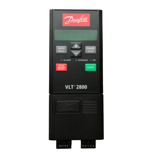
Настройку параметров
преобразователя частоты VLT2800
производят, используяпанель местного
управления.Панель местного управлениярасположена непосредственно на передней
крышке преобразователя частотыVLT2800.
Внешний видпанели местного управленияприведен на рис. 2.1.

Рис.
2.1. Панель местного управления
Панель управления
разделена на четыре функциональные
части:
-
Шестиразрядный
светодиодный дисплей. -
Кнопки для изменения
параметров и выбора функции отображения. -
Светодиодные
индикаторы. -
Кнопки для местного
управления.
Все данные
отображаются на шестиразрядном
светодиодном дисплее, позволяющем
непрерывно отображать один из рабочих
параметров во время нормальной работы
преобразователя частоты. Кроме дисплея
на панели местного управления установлены
три светодиодных индикатора, указывающие
включение питания (ON),
наличие предупреждения (WARNING)
и аварийного сигнала (ALARM).
Большинство параметров преобразователя
частоты можно изменить с панели
управления, если только для параметра
018Блокировка изменения параметровне было задано значение 1 –Заблокировано.
Кнопка «QUICKMENU» обеспечивает доступ
к параметрам, используемым в быстром
меню.
Кнопка «CHANGEDATE» используется как для
изменения значения параметра, так и для
подтверждения изменения значения
параметра.
Кнопки «+» и «–»
используются для выбора параметров и
для изменения значения параметров. Эти
кнопки используются также в режиме
отображения для выбора рабочих параметров.
Для получения
доступа ко всем параметрам кнопки «QUICKMENUи +» следует нажать
одновременно.
Кнопка «STOPRESET» используется для
останова подключенного двигателя или
для сброса преобразователя частоты
после отключения. Кнопка может быть
выбрана какАктивная«1», так иНеактивная«0» в параметре 014Местный
останов/сброс. В режиме отображения
при включении функции останова изображение
на дисплее будет мигать. Если в параметре
014Местный останов/сброскнопка
«STOPRESET»
выбрана какНеактивная«0» и команда
останова не поступает на дискретные
входы или по последовательному каналу
связи, то двигатель может быть остановлен
только путем отключения преобразователя
частоты от сети электропитания.
Кнопка «START»
используется для запуска преобразователя
частоты. Эта кнопка всегда активна.
После
перепрограммирования преобразователь
частоты можно возвратить в исходное
состояние. Для этого необходимо отключить
сетевое напряжение. Удерживая три кнопки
«QUICKMENU», +
и «CHANGEDATE»
нажатыми, включите напряжение сети.
Отпустите кнопки. Теперь преобразователь
частоты снова запрограммирован на
заводские установки.
Программировать
преобразователь частоты VLT2800
можно также, используя выноснуюместную
панель управленияпреобразователя
частотыDanfossFC– 302. Для этого случая последовательность
действий описана в лабораторной работе
№2.
2.1. Режим вывода данных на светодиодный дисплей
При нормальной
работе по выбору оператора на дисплее
может непрерывно отображаться один из
рабочих параметров. С помощью кнопок
«+» и «–» в режиме отображения могут
выводиться следующие физические
величины:
-
Выходная частота
преобразователя, Гц; -
Выходной ток, А;
-
Выходное напряжение,
В; -
Напряжение
промежуточного звена постоянного тока,
В; -
Выходная мощность,
кВт; -
Масштабированная
выходная частота, о.е.
Например, при
выборе физической величины «Выходная
частота преобразователя» на экране
дисплея появится сообщение:

Соседние файлы в папке Толпаров
- #
- #
- #
30.05.20152.85 Mб8характеристики ЛБ4.xmcd
- #
Оглавление
Быстрая настройка
3
Общее предупреждение
3
Механический монтаж
3
Электрический монтаж, питание
3
Электромонтаж, кабели управления
3
Программирование
3
Запуск двигателя
4
Правила безопасности
4
Предотвращение самопроизвольного пуска
4
VLT 2800, Введение
6
Версия программного обеспечения
6
Предупреждение о высоком напряжении
7
Правила техники безопасности
7
Предотвращение самопроизвольного пуска
7
Панель управления
9
Ручная инициализация
9
Ручной и автоматический режимы работы
11
Автоматическая адаптация двигателя
11
Программирование
12
Работа и отображение данных
12
Нагрузка и двигатель
21
Задания и ограничения
33
Задания и ограничения
41
Специальные функции
52
Улучшенный режим ожидания
63
Монтаж
69
Габаритные и присоединительные размеры
69
Механический монтаж
73
Общие сведения об электрическом монтаже
75
Электрический монтаж с учетом требований ЭМС
76
Электрический монтаж
77
Защитная скоба
79
Входные плавкие предохранители
79
Подключение к сети питания
79
Подключение двигателя
80
Выключатель фильтра ВЧ-помех
80
Направление вращения двигателя
81
Параллельное соединение двигателей
81
Кабели двигателей
81
Тепловая защита двигателя
82
Подключение тормозного резистора
82
Подключение заземления
82
Устройство разделения нагрузки
82
Момент затяжки, силовые клеммы
83
Серия VLT® 2800
MG.27.A2.50 — VLT
®
– зарегистрированный товарный знак компании Danfoss
1
- Manuals
- Brands
- Danfoss Manuals
- DC Drives
- VLT 2800 Series
- Operating instructions manual
-
Contents
-
Table of Contents
-
Bookmarks
Quick Links
Operating Instructions
®
VLT
2800
Related Manuals for Danfoss VLT 2800 Series
Summary of Contents for Danfoss VLT 2800 Series
-
Page 1
Operating Instructions ® 2800… -
Page 2: Table Of Contents
Safety clamp Pre-fuses Mains connection Motor connection RFI switch Direction of motor rotation Parallel connection of motors Motor cables Motor thermal protection Brake connection Earth connection Load sharing Tightening Torque, Power Terminals ® MG.27.A2.02 — VLT is a registered Danfoss trademark…
-
Page 3
General technical data Technical data, mains supply 1 x 220 — 240 V/3 x 200-240V Technical data, mains supply 3 x 380 — 480 V Available literature Supplied with the unit Index ® MG.27.A2.02 — VLT is a registered Danfoss trademark… -
Page 4: Quick Setup
Remote operation er, i.e. U, V, W. The screen ends in a screen connector. [0], i.e. via the control terminals, or Local [1], i.e. via the control unit. ® MG.27.A2.02 — VLT is a registered Danfoss trademark…
-
Page 5: Motor Start
The earth leakage current is higher than 3.5 Protection against motor overload is not in- cluded in the factory setting. If this function is required, set parameter 128 Motor thermal ® MG.27.A2.02 — VLT is a registered Danfoss trademark…
-
Page 6: Introduction To Vlt 2800
VLT 2800 Operating Instructions Software version: 3.1x This Design Guide can be used for all VLT 2800 Series frequency converters with software version 3.1x. The software version number can be seen from parameter 640. Warning It can be extremely dangerous to touch the electrical parts even when the mains supply has been disconnected.
-
Page 7: High Voltage Warning
5000 m (16 404 ft.). Please ensure that no unintended start occurs, these contact Danfoss Drives for further infor- stop functions are not sufficient. mation. While parameters are being changed, the motor may start.
-
Page 8: Control Unit
See also [QUICK MENU] + [+]. [CHANGE DATA] is used for changing a setting. The [CHANGE DATA] key is also used for confirming a change of parameter settings. ® MG.27.A2.02 — VLT is a registered Danfoss trademark…
-
Page 9: Hand Auto
Hand mode is activated: • Hand Start (LCP2) • Off Stop (LCP2) The display shows that in parameter 128 Motor thermal • Auto Start (LCP2) protection the selection made is Thermistor trip [2]. ® MG.27.A2.02 — VLT is a registered Danfoss trademark…
-
Page 10: Automatic Motor Tuning
When the frequency converter is in Hand mode the readout will be like: and the reference can be changed by using the fol- lowing keys: Please note, that parameter 020 may block the choice of mode. ® MG.27.A2.02 — VLT is a registered Danfoss trademark…
-
Page 11: Programming
If Local operation [1], is selected, the frequency con- verter is controlled via: = factory setting, () = display text, [] = value for use in communication via serial communication port ® MG.27.A2.02 — VLT is a registered Danfoss trademark…
-
Page 12
Setup 1-4 [1]-[4] are indi- vidual Setups that can be programmed freely during = factory setting, () = display text, [] = value for use in communication via serial communication port ® MG.27.A2.02 — VLT is a registered Danfoss trademark… -
Page 13
Resulting reference [unit] play mode. In parameters 010-012 Display readout you (reference [unit]) = factory setting, () = display text, [] = value for use in communication via serial communication port ® MG.27.A2.02 — VLT is a registered Danfoss trademark… -
Page 14
The display Analog input 53 [V] gives the voltage value of terminal = factory setting, () = display text, [] = value for use in communication via serial communication port ® MG.27.A2.02 — VLT is a registered Danfoss trademark… -
Page 15
(LOC+DIG CTRL/AS P100) reference signal is negative, the local reference will be set to 0. = factory setting, () = display text, [] = value for use in communication via serial communication port ® MG.27.A2.02 — VLT is a registered Danfoss trademark… -
Page 16
If Not active [0] is selected in this parameter, the [JOG]- key will be inactive. = factory setting, () = display text, [] = value for use in communication via serial communication port ® MG.27.A2.02 — VLT is a registered Danfoss trademark… -
Page 17
Parameter 003 Local reference is to be Quick Menu key is active. zeroed. = factory setting, () = display text, [] = value for use in communication via serial communication port ® MG.27.A2.02 — VLT is a registered Danfoss trademark… -
Page 18
Quick Menu will start with this parameter every time Quick Menu is activated. Please note that parameter 024 User-defined Quick Menu and parameter 025 Quick Menu setup are reset to the factory setting during initialisation. ® MG.27.A2.02 — VLT is a registered Danfoss trademark… -
Page 19: Load And Motor
Load and slip compensation are not active if variable torque or special motor mode have been selected. = factory setting, () = display text, [] = value for use in communication via serial communication port ® MG.27.A2.02 — VLT is a registered Danfoss trademark…
-
Page 20
Description of choice: Select a value that corresponds to the nameplate data on the motor. = factory setting, () = display text, [] = value for use in communication via serial communication port ® MG.27.A2.02 — VLT is a registered Danfoss trademark… -
Page 21
Description of choice: cedure by giving a STOP signal. can be set as follows: = factory setting, () = display text, [] = value for use in communication via serial communication port ® MG.27.A2.02 — VLT is a registered Danfoss trademark… -
Page 22
50% reduction of U/F ratio. Default value is OFF — 100% [OFF — 100] OFF. OFF % [OFF] = factory setting, () = display text, [] = value for use in communication via serial communication port ® MG.27.A2.02 — VLT is a registered Danfoss trademark… -
Page 23
This is where to choose the required mode during the start delay time (parameter 120 Start delay time). = factory setting, () = display text, [] = value for use in communication via serial communication port ® MG.27.A2.02 — VLT is a registered Danfoss trademark… -
Page 24
The frequency converter can monitor the motor tem- alarm. perature in two different ways: = factory setting, () = display text, [] = value for use in communication via serial communication port ® MG.27.A2.02 — VLT is a registered Danfoss trademark… -
Page 25
This function cannot protect the individual motors in the case of motors linked in par- allel. = factory setting, () = display text, [] = value for use in communication via serial communication port ® MG.27.A2.02 — VLT is a registered Danfoss trademark… -
Page 26
= factory setting, () = display text, [] = value for use in communication via serial communication port ® MG.27.A2.02 — VLT is a registered Danfoss trademark… -
Page 27
102-106. = factory setting, () = display text, [] = value for use in communication via serial communication port ® MG.27.A2.02 — VLT is a registered Danfoss trademark… -
Page 28
If 1.0 is selected, this corresponds to the AC brake being inactive. = factory setting, () = display text, [] = value for use in communication via serial communication port ® MG.27.A2.02 — VLT is a registered Danfoss trademark… -
Page 29: References & Limits
A value can be selected from f to the value chosen in parameter 200 Output frequency range. = factory setting, () = display text, [] = value for use in communication via serial communication port ® MG.27.A2.02 — VLT is a registered Danfoss trademark…
-
Page 30
0. = factory setting, () = display text, [] = value for use in communication via serial communication port ® MG.27.A2.02 — VLT is a registered Danfoss trademark… -
Page 31
Description of choice: Set the required ramp-down time. = factory setting, () = display text, [] = value for use in communication via serial communication port ® MG.27.A2.02 — VLT is a registered Danfoss trademark… -
Page 32
Sum (sum) via the digital inputs or via serial communication. Relative (relative) External/preset (external/preset) = factory setting, () = display text, [] = value for use in communication via serial communication port ® MG.27.A2.02 — VLT is a registered Danfoss trademark… -
Page 33
= factory setting, () = display text, [] = value for use in communication via serial communication port ® MG.27.A2.02 — VLT is a registered Danfoss trademark… -
Page 34
The warning functions are can be programmed to give a warning signal via ter- = factory setting, () = display text, [] = value for use in communication via serial communication port ® MG.27.A2.02 — VLT is a registered Danfoss trademark… -
Page 35
Enter the frequencies to be avoided. See also param- eter 229 Frequency bypass, bandwidth. = factory setting, () = display text, [] = value for use in communication via serial communication port ® MG.27.A2.02 — VLT is a registered Danfoss trademark… -
Page 36: Inputs And Outputs
(terminals 18-33). converter «let go» of the motor immediately (output = factory setting, () = display text, [] = value for use in communication via serial communication port ® MG.27.A2.02 — VLT is a registered Danfoss trademark…
-
Page 37
Is not active at Process regulation, closed loop . See also parameter 200 Output frequency range/ direction. = factory setting, () = display text, [] = value for use in communication via serial communication port ® MG.27.A2.02 — VLT is a registered Danfoss trademark… -
Page 38
Reset and start can be used as a start function. If 24 V are connected to the digital input, this will cause the = factory setting, () = display text, [] = value for use in communication via serial communication port ® MG.27.A2.02 — VLT is a registered Danfoss trademark… -
Page 39
Reference [1]. If this function is selected, the reference can be changed by means of an analogue reference = factory setting, () = display text, [] = value for use in communication via serial communication port ® MG.27.A2.02 — VLT is a registered Danfoss trademark… -
Page 40
[4] overruled to stop with subsequent trip [5] = factory setting, () = display text, [] = value for use in communication via serial communication port ® MG.27.A2.02 — VLT is a registered Danfoss trademark… -
Page 41
Output current higher than I par. 223 0-20 mA/ 4-20 mA. (above current low) [13] = factory setting, () = display text, [] = value for use in communication via serial communication port ® MG.27.A2.02 — VLT is a registered Danfoss trademark… -
Page 42
VLT 2800 Design Guide). on the inputs. The mains voltage lies within the voltage limits. = factory setting, () = display text, [] = value for use in communication via serial communication port ® MG.27.A2.02 — VLT is a registered Danfoss trademark… -
Page 43
This parameter is used for setting the pulse output sig- nal’s maximum frequency. = factory setting, () = display text, [] = value for use in communication via serial communication port ® MG.27.A2.02 — VLT is a registered Danfoss trademark… -
Page 44
Reset. Counter stop and Speed-compensated stop can be combined with or without reset. = factory setting, () = display text, [] = value for use in communication via serial communication port ® MG.27.A2.02 — VLT is a registered Danfoss trademark… -
Page 45: Special Functions
(RESET AT POWER UP) [11] application, like the ETR will protect the motor if se- lected. = factory setting, () = display text, [] = value for use in communication via serial communication port ® MG.27.A2.02 — VLT is a registered Danfoss trademark…
-
Page 46
(parameters 308/314 Analogue inputs). = factory setting, () = display text, [] = value for use in communication via serial communication port ® MG.27.A2.02 — VLT is a registered Danfoss trademark… -
Page 47
[27] come unstable in the case of overshooting. In wg (in wg) [28] = factory setting, () = display text, [] = value for use in communication via serial communication port ® MG.27.A2.02 — VLT is a registered Danfoss trademark… -
Page 48
D-gain at higher frequencies. Torque characteristic a selection has been made of = factory setting, () = display text, [] = value for use in communication via serial communication port ® MG.27.A2.02 — VLT is a registered Danfoss trademark… -
Page 49
428 F3 frequency quency = factory setting, () = display text, [] = value for use in communication via serial communication port ® MG.27.A2.02 — VLT is a registered Danfoss trademark… -
Page 50
Process PID integration time (PROC. INTEGR. T.) Value: 0.01 — 9999.99 (OFF) = factory setting, () = display text, [] = value for use in communication via serial communication port ® MG.27.A2.02 — VLT is a registered Danfoss trademark… -
Page 51
OK — same direction [1] should be selected if in parameter = factory setting, () = display text, [] = value for use in communication via serial communication port ® MG.27.A2.02 — VLT is a registered Danfoss trademark… -
Page 52
The greater the reduction value, the faster the reaction to a generator overload. Should only be used if there = factory setting, () = display text, [] = value for use in communication via serial communication port ® MG.27.A2.02 — VLT is a registered Danfoss trademark… -
Page 53
600 Service functions are not WARNING) included in this manual. Please contact Warning (WARNING) Danfoss and ask for the VLT 2800 Design Guide. Function: Select the function which is to be activated if the mains imbalance becomes too high or if a phase is missing. -
Page 54: Enhanced Sleep Mode
Sleep-mode or trips case of dry run. This is assured by the Dry run detec- due to dry run, depending on the configuration. tion feature. ® MG.27.A2.02 — VLT is a registered Danfoss trademark…
-
Page 55
= factory setting, () = display text, [] = value for use in communication via serial communication port ® MG.27.A2.02 — VLT is a registered Danfoss trademark… -
Page 56
202 Output frequency high over the whole frequency range. limit, f = factory setting, () = display text, [] = value for use in communication via serial communication port ® MG.27.A2.02 — VLT is a registered Danfoss trademark… -
Page 57
— set in parameter 201. = factory setting, () = display text, [] = value for use in communication via serial communication port ® MG.27.A2.02 — VLT is a registered Danfoss trademark… -
Page 58
= factory setting, () = display text, [] = value for use in communication via serial communication port ® MG.27.A2.02 — VLT is a registered Danfoss trademark… -
Page 59: Installation
Please note that all filter options must be vertically mounted. VLT 2803-2815 200-240 Volt VLT 2805-2815 380-480 Volt VLT 2840 220-240 V, PD2 VLT 2880-82 380-480V VLT 2822 200-240 Volt VLT 2822-2840 380-480 Volt ® MG.27.A2.02 — VLT is a registered Danfoss trademark…
-
Page 60
Motor coils (195N3110) Terminal cover The drawing below gives the dimensions for NEMA 1 terminal covers for VLT 2803-2875. Dimension ‘a’ depends on the unit type. RFI 1B filter (195N3103) IP 21 solution ® MG.27.A2.02 — VLT is a registered Danfoss trademark… -
Page 61
VLT 2822 200-240 V, VLT 2822-2840 380-480 V 195N2119 VLT 2840 200-240 V, VLT 2822 PD2, TR1 2855-2875 195N2120 380-480 V TR1 2880-2882 380-480 V, VLT 2840 PD2 195N2126 EMC filter for long motor cables 192H4719 192H4720 ® MG.27.A2.02 — VLT is a registered Danfoss trademark… -
Page 62
® 2800 Series 192H4893 ® MG.27.A2.02 — VLT is a registered Danfoss trademark… -
Page 63: Mechanical Installation
100 mm air on each side. This means that side-by-side mounting is not allowed. Spacing for mechanical installation All units require a minimum of 100 mm air between other components and vents of the enclosure. ® MG.27.A2.02 — VLT is a registered Danfoss trademark…
-
Page 64: General Information About Electrical Installation
DC content may develop in the faulty cur- rent. Never use an RCD (ELCB relay), type A, as it is not suitable for DC faulty currents. If RCD relays are ® MG.27.A2.02 — VLT is a registered Danfoss trademark…
-
Page 65: Emc-Correct Electrical Installation
The illustration below shows EMC-correct electrical in- at high frequencies. Use cable clamps in- stallation, in which the frequency converter has been stead. fitted in an installation cabinet and connected to a PLC. ® MG.27.A2.02 — VLT is a registered Danfoss trademark…
-
Page 66: Electrical Installation
® 2800 Series Electrical installation See also the section Brake Connection. VLT 2822 200-240 V, 2822-2840 380-480 V VLT 2803-2815 200-240 V, 2805-2815 380-480 V ® MG.27.A2.02 — VLT is a registered Danfoss trademark…
-
Page 67
VLT 2840 200-240 V, VLT 2822 PD2, 2855-2875 380-480 V VLT 2880-2882 380-480 V, VLT 2840 PD2 Please note that the units will be supplied with two bottom plates; one for metric glands and one for con- duits. ® MG.27.A2.02 — VLT is a registered Danfoss trademark… -
Page 68: Safety Clamp
See Technical data for correct dimensioning of cable cross-section. See also the section entitled Galvanic isolation for further details. Please check that the mains voltage fits the mains voltage of the frequency con- ® MG.27.A2.02 — VLT is a registered Danfoss trademark…
-
Page 69: Motor Connection
(OFF). For further reference, see IEC 364-3. In case optimum EMC performance is needed, parallel motors are connected or the motor cable length is ® MG.27.A2.02 — VLT is a registered Danfoss trademark…
-
Page 70: Parallel Connection Of Motors
[8] when motors are connected in parallel. Motor cables See Technical data for correct dimensioning of motor cable cross-section and length. Always comply with national and local regulations on cable cross-section. ® MG.27.A2.02 — VLT is a registered Danfoss trademark…
-
Page 71: Motor Thermal Protection
To increase safety you can install an RCD (Residual Current Device), which guarantees that the frequency converter trips when leak current becomes too high. See also RCD Application Note MN.90.GX.02. ® MG.27.A2.02 — VLT is a registered Danfoss trademark…
-
Page 72: Load Sharing
® 2800 Series Load sharing Use 6.3 mm Faston Plugs for DC (Load Sharing). Contact Danfoss or see instructions no. MI.50.NX.02 Load sharing provides the facility to connect several for further information. frequency converters’ DC intermediate circuits. This requires that the installation is extended using extra No.
-
Page 73: Electrical Installation, Control Cables
100 nF capacitor between the screen and the chassis. Control cables must be screened/armoured. The screen must be connected to the frequency converter ® MG.27.A2.02 — VLT is a registered Danfoss trademark…
-
Page 74: Tightening Torques, Control Cables
1 — 2 make (normally open) plug on the control card. Ordering number: 175N0131. 01 — 03 1 — 3 break (normally closed) LCP control unit with ordering number 175Z0401 is not to be connected. ® MG.27.A2.02 — VLT is a registered Danfoss trademark…
-
Page 75: Connection Examples
Par. 305 Digital input = Jog [13] Par. 314 Analog input = Feedback [2] Par. 315 Terminal 60, min. scaling = 4 mA Par. 316 Terminal 60, max. scaling = 20 mA ® MG.27.A2.02 — VLT is a registered Danfoss trademark…
-
Page 76
® 2800 Series ® MG.27.A2.02 — VLT is a registered Danfoss trademark… -
Page 77
® 2800 Series ® MG.27.A2.02 — VLT is a registered Danfoss trademark… -
Page 78: Display Readout
The frequency converter shows the present Hand mode reference frequency in Herz (Hz). The frequency converter shows scaled output fre- quency (the present output frequency x parameter 008). ® MG.27.A2.02 — VLT is a registered Danfoss trademark…
-
Page 79
5 — 10 sec. Note: pends on the device, and is set at 5 — 10 sec. An The frequency converter will trip with an alarm 7 (over- ® MG.27.A2.02 — VLT is a registered Danfoss trademark… -
Page 80
221 Current Limit , and the frequency converter but there will not be a warning in the display. will trip after a set time, selected in parameter 409 Trip delay overcurrent. ® MG.27.A2.02 — VLT is a registered Danfoss trademark… -
Page 81
There is inconsistency between the registered motor data. Check the motor data for the relevant setup. ALARM 37-45: Internal fault If one of these failures occurs, please contact Danfoss. ALARM 52: AMT missing motor phase The AMT function has detected a missing motor Alarm 37, internal fault number 0: Communication fault phase. -
Page 82: Warning Words, Extended Status Words And Alarmwords
000010 Catch-up 000020 Feedback high 000040 Feedback low 000080 Output current high 000100 Output current low 000200 Output frequency high 000400 Output frequency low 002000 Braking 008000 Out of frequency range ® MG.27.A2.02 — VLT is a registered Danfoss trademark…
-
Page 83: Special Conditions
This can be done by looking at existing in- stallations in the same environment. Typical indicators of harmful airborne liquids are water or oil on metal parts or corrosion of metal parts. Too many dust par- ® MG.27.A2.02 — VLT is a registered Danfoss trademark…
-
Page 84: Derating For High Switching Frequency — Vlt 2800
PELV is observed for these, even though there is mains potential at the relay terminals. The circuit elements described below form the safe electric separation. They fulfill the requirements for re- ® MG.27.A2.02 — VLT is a registered Danfoss trademark…
-
Page 85: Emc Emission
(ISM) high-frequency equipment. Class 1A: Equipment used in an industrial environment. Class 1B: Equipment used in areas with a public supply network (residential, commerce and light industry). UL Standard This device is UL-approved. ® MG.27.A2.02 — VLT is a registered Danfoss trademark…
-
Page 86: General Technical Data
4 kΩ Input resistance, R (terminal 33) approx. 2 kΩ All digital inputs are galvanically isolated from the supply voltage (PELV) and other high-voltage terminals. See section entitled Galvanic Isolation. ® MG.27.A2.02 — VLT is a registered Danfoss trademark…
-
Page 87
Max. error: 0.2 % of full scale Resolution on frequency output 10 bit The digital output is galvanically isolated from the supply voltage (PELV) and other high-voltage terminals. See section entitled Galvanic Isolation. ® MG.27.A2.02 — VLT is a registered Danfoss trademark… -
Page 88
The relay contact is separated from the rest of the circuit by strengthened isolation. Note: Rated values resistive load — cosphi >0.8 for up to 300,000 operations. Inductive loads at cosphi 0.25 approximately 50% load or 50% life time. ® MG.27.A2.02 — VLT is a registered Danfoss trademark… -
Page 89
EN 61081-2, EN 61800-3, EN 55011 EN 50082-1/2, EN 61000-4-2, EN 61000-4-3, EN 61000-4-4, EN 61000-4-5, EN EMC standards, Immunity 61000-4-6, EN 61800-3 See section on special conditions in the Design Guide ® MG.27.A2.02 — VLT is a registered Danfoss trademark… -
Page 90
• The frequency converter is protected against earth fault on motor terminals U, V, W. ® MG.27.A2.02 — VLT is a registered Danfoss trademark… -
Page 91: Technical Data, Mains Supply 1 X 220 — 240 V/3 X 200-240V
100,000 amps RMS (symmetrical), 500 V maximum. 3. Measured using a 25 m screened/armoured motor cable with a rated load and rated frequency. 4. IP20 is standard for VLT 2805-2875, whereas NEMA 1 is an option. ® MG.27.A2.02 — VLT is a registered Danfoss trademark…
-
Page 92: Technical Data, Mains Supply 3 X 380 — 480 V
See table under Pre-fuses. 3. Measured using a 25 m screened/armoured motor cable with a rated load and rated frequency. 4. IP20 is standard for VLT 2805-2875, whereas NEMA 1 is an option. ® MG.27.A2.02 — VLT is a registered Danfoss trademark…
-
Page 93: Available Literature
VLT 2800 DeviceNet cable MI.28.F1.02 Cold plate MI.28.D1.02 Precise stop MI.28.C1.02 Communication with VLT 2800: Profibus manual MG.90.AX.YY VLT 2800 DeviceNet manual MG.90.BX.YY X = version number YY = language version ® MG.27.A2.02 — VLT is a registered Danfoss trademark…
-
Page 94
This number refers to a conversion figure to be used Unsigned 32 when writing or reading via serial communication with Text string a frequency converter. See Data character in Serial communication in the VLT 2800 Design Guide. ® MG.27.A2.02 — VLT is a registered Danfoss trademark… -
Page 95
Brake cut out value 3.0 Hz Brake cut in frequency 3.0 Hz Current, minimum value Leak reactance depends on motor selected Internal ventilator control Automatic AC brake factor 1.30 Reset voltage vector ® MG.27.A2.02 — VLT is a registered Danfoss trademark… -
Page 96
0.0 Hz Warn. High frequency 132.0 Hz Warn. Low Feedback -4000.000 Warn. High Feedback 4000.000 Frequency bypass, 0 Hz (OFF) bandwidth Frequency bypass 1 0.0 Hz Frequency bypass 2 0.0 Hz ® MG.27.A2.02 — VLT is a registered Danfoss trademark… -
Page 97
This number refers to a conversion figure to be used Unsigned 32 when writing or reading via serial communication with Text string a frequency converter. See Data character in Serial communication in the VLT 2800 Design Guide. ® MG.27.A2.02 — VLT is a registered Danfoss trademark… -
Page 98
Maximum pump frequency Minimum pump power Maximum pump power No flow power compensation Dry run time out Dry run interlock timer 30 min. Initial ramp Fill rate Filled setpoint Parameter 414 ® MG.27.A2.02 — VLT is a registered Danfoss trademark… -
Page 99
Data readout: Status word Data readout: Bus feedback 1 Data readout: Inverter temperature Data readout: Alarm word Data readout: Control word Data readout: Warning word Data readout: Extended status word Data readout: Pulse count ® MG.27.A2.02 — VLT is a registered Danfoss trademark… -
Page 100
This number refers to a conversion figure to be used Unsigned 32 when writing or reading via serial communication with Text string a frequency converter. See Data character in Serial communication in the VLT 2800 Design Guide. ® MG.27.A2.02 — VLT is a registered Danfoss trademark… -
Page 101: Index
Motor thermal protection EMC emission Motor voltage EMC-correct electrical installation ETR — Electronic Thermal Relay Extra protection Operating mode at power-up, local operation Order form Output frequency Fan control Overmodulation function Feedback conversion ® MG.27.A2.02 — VLT is a registered Danfoss trademark…
-
Page 102
Special motor mode Speed comp delay Speed control, closed loop Speed control, open loop Speed PID Speed up/down Square root Start Start delay Start frequency Start function Start torque Start voltage Start/stop ® MG.27.A2.02 — VLT is a registered Danfoss trademark… -
Page 103
*MG27A202* 195R0027 MG27A202 Rev. 2006-12-08…
Оглавление
Быстрая настройка
3
Общее предупреждение
3
Механический монтаж
3
Электрический монтаж, питание
3
Электромонтаж, кабели управления
3
Программирование
3
Запуск двигателя
4
Правила безопасности
4
Предотвращение самопроизвольного пуска
4
VLT 2800, Введение
6
Версия программного обеспечения
6
Предупреждение о высоком напряжении
7
Правила техники безопасности
7
Предотвращение самопроизвольного пуска
7
Панель управления
9
Ручная инициализация
9
Ручной и автоматический режимы работы
11
Автоматическая адаптация двигателя
11
Программирование
12
Работа и отображение данных
12
Нагрузка и двигатель
21
Задания и ограничения
33
Задания и ограничения
41
Специальные функции
52
Улучшенный режим ожидания
63
Монтаж
69
Габаритные и присоединительные размеры
69
Механический монтаж
73
Общие сведения об электрическом монтаже
75
Электрический монтаж с учетом требований ЭМС
76
Электрический монтаж
77
Защитная скоба
79
Входные плавкие предохранители
79
Подключение к сети питания
79
Подключение двигателя
80
Выключатель фильтра ВЧ-помех
80
Направление вращения двигателя
81
Параллельное соединение двигателей
81
Кабели двигателей
81
Тепловая защита двигателя
82
Подключение тормозного резистора
82
Подключение заземления
82
Устройство разделения нагрузки
82
Момент затяжки, силовые клеммы
83
Серия VLT® 2800
MG.27.A2.50 — VLT
®
– зарегистрированный товарный знак компании Danfoss
1
Настройку параметров
преобразователя частоты VLT2800
производят, используяпанель местного
управления.Панель местного управлениярасположена непосредственно на передней
крышке преобразователя частотыVLT2800.
Внешний видпанели местного управленияприведен на рис. 2.1.
Рис.
2.1. Панель местного управления
Панель управления
разделена на четыре функциональные
части:
-
Шестиразрядный
светодиодный дисплей. -
Кнопки для изменения
параметров и выбора функции отображения. -
Светодиодные
индикаторы. -
Кнопки для местного
управления.
Все данные
отображаются на шестиразрядном
светодиодном дисплее, позволяющем
непрерывно отображать один из рабочих
параметров во время нормальной работы
преобразователя частоты. Кроме дисплея
на панели местного управления установлены
три светодиодных индикатора, указывающие
включение питания (ON),
наличие предупреждения (WARNING)
и аварийного сигнала (ALARM).
Большинство параметров преобразователя
частоты можно изменить с панели
управления, если только для параметра
018Блокировка изменения параметровне было задано значение 1 –Заблокировано.
Кнопка «QUICKMENU» обеспечивает доступ
к параметрам, используемым в быстром
меню.
Кнопка «CHANGEDATE» используется как для
изменения значения параметра, так и для
подтверждения изменения значения
параметра.
Кнопки «+» и «–»
используются для выбора параметров и
для изменения значения параметров. Эти
кнопки используются также в режиме
отображения для выбора рабочих параметров.
Для получения
доступа ко всем параметрам кнопки «QUICKMENUи +» следует нажать
одновременно.
Кнопка «STOPRESET» используется для
останова подключенного двигателя или
для сброса преобразователя частоты
после отключения. Кнопка может быть
выбрана какАктивная«1», так иНеактивная«0» в параметре 014Местный
останов/сброс. В режиме отображения
при включении функции останова изображение
на дисплее будет мигать. Если в параметре
014Местный останов/сброскнопка
«STOPRESET»
выбрана какНеактивная«0» и команда
останова не поступает на дискретные
входы или по последовательному каналу
связи, то двигатель может быть остановлен
только путем отключения преобразователя
частоты от сети электропитания.
Кнопка «START»
используется для запуска преобразователя
частоты. Эта кнопка всегда активна.
После
перепрограммирования преобразователь
частоты можно возвратить в исходное
состояние. Для этого необходимо отключить
сетевое напряжение. Удерживая три кнопки
«QUICKMENU», +
и «CHANGEDATE»
нажатыми, включите напряжение сети.
Отпустите кнопки. Теперь преобразователь
частоты снова запрограммирован на
заводские установки.
Программировать
преобразователь частоты VLT2800
можно также, используя выноснуюместную
панель управленияпреобразователя
частотыDanfossFC– 302. Для этого случая последовательность
действий описана в лабораторной работе
№2.
2.1. Режим вывода данных на светодиодный дисплей
При нормальной
работе по выбору оператора на дисплее
может непрерывно отображаться один из
рабочих параметров. С помощью кнопок
«+» и «–» в режиме отображения могут
выводиться следующие физические
величины:
-
Выходная частота
преобразователя, Гц; -
Выходной ток, А;
-
Выходное напряжение,
В; -
Напряжение
промежуточного звена постоянного тока,
В; -
Выходная мощность,
кВт; -
Масштабированная
выходная частота, о.е.
Например, при
выборе физической величины «Выходная
частота преобразователя» на экране
дисплея появится сообщение:
Соседние файлы в папке Толпаров
- #
- #
- #
30.05.20152.85 Mб10характеристики ЛБ4.xmcd
- #