Скачать
EN
Owner’s Manual
Precautions
pages 5, 6
Quick Start Guide
pages 9 to 11
Troubleshooting
page 29 to 31
- Manuals
- Brands
- Yamaha Manuals
- Music Mixer
- MG16XU
Manuals and User Guides for Yamaha MG16XU. We have 3 Yamaha MG16XU manuals available for free PDF download: Owner’s Manual, Technical Specifications
Yamaha MG16XU Owner’s Manual (40 pages)
Brand: Yamaha
|
Category: Music Mixer
|
Size: 5.59 MB
Table of Contents
-
Important Safety Instructions
3
-
Precautions
5
-
Table of Contents
7
-
-
Contents
7
-
Main Features
8
-
Quick Start Guide
9
-
Step 1 Preparing the Power Supply
9
-
Step 2 Making Connections
9
-
Step 3 Powering up the System
9
-
Step 4 Getting Sound to the Speakers
10
-
Step 5 Using the Built-In Effects (XU Models Only)
11
-
-
Setup
12
-
Setup Examples
12
-
Sound Reinforcement for Live Performance
12
-
-
Controls and Connectors
14
-
Front Panel
14
-
Rear Panel
15
-
Input Channel Block
16
-
Channel Faders
19
-
Mono Input Channels
20
-
Stereo Input Channels
21
-
-
Built-In Effects Block (XU Models Only)
22
-
Master Block
24
-
Power Block
27
-
USB Block (XU Models Only)
28
-
-
Troubleshooting
29
-
When no Sound Is Output
29
-
Other
31
-
-
Appendix
32
-
General Specifications
32
-
Effect Programs
33
-
Jack and Connector List
34
-
Connector Types
34
-
Rack Mounting
35
-
Index
36
-
Advertisement
Yamaha MG16XU Owner’s Manual (40 pages)
Brand: Yamaha
|
Category: Music Mixer
|
Size: 5.42 MB
Yamaha MG16XU Technical Specifications (2 pages)
Brand: Yamaha
|
Category: Music Mixer
|
Size: 0.46 MB
Table of Contents
-
Analog Input Characteristics
1
-
Technical Specifications
1
-
General Specifications
1
-
Analog Output Characteristics
1
Advertisement
Advertisement
Related Products
-
Yamaha MG16X
-
Yamaha MG16X CV
-
Yamaha MG16
-
Yamaha MG166C
-
Yamaha MG166CX
-
Yamaha MG166C-USB2
-
Yamaha MG16/6FX
-
Yamaha MG166
-
Yamaha MG166CX-USB
-
Yamaha MG166C-USB
Yamaha Categories
Motorcycle
Musical Instrument
Electronic Keyboard
Receiver
Amplifier
More Yamaha Manuals
![]()
РуководствоOwner’sпользователяManual
|
Правила техники безопасности |
Стр. 5, 6 |
||
|
Краткое руководство по эксплуатации |
Стр. 9–11 |
||
|
Поиск иустранение неисправностей |
Стр. 29–31 |
||
|
RU |
|||

The above warning is located on the rear of the unit.
L’avertissement ci-dessus est situé à l’arrière de l’appareil.
Explanation of Graphical Symbols
Explication des symboles
The lightning flash with arrowhead symbol within an equilateral triangle is intended to alert the user to the presence of uninsulated «dangerous voltage» within the product’s enclosure that may be of sufficient magnitude to constitute a risk of electric shock to persons.
L’éclair avec une flèche à l’intérieur d’un triangle équilatéral est destiné à attirer l’attention de l’utilisateur sur la présence d’une « tension dangereuse » non isolée à l’intérieur de l’appareil, pouvant être suffisamment élevée pour constituer un risque d’électrocution.
The exclamation point within an equilateral triangle is intended to alert the user to the presence of important operating and maintenance (servicing) instructions in the literature accompanying the product.
Le point d’exclamation à l’intérieur d’un triangle équilatéral est destiné à attirer l’attention de l’utilisateur sur la présence d’instructions importantes sur l’emploi ou la maintenance (réparation) de l’appareil dans la documentation fournie.
IMPORTANT SAFETY INSTRUCTIONS
1 Read these instructions.
2 Keep these instructions.
3Heed all warnings.
4Follow all instructions.
5 Do not use this apparatus near water.
6Clean only with dry cloth.
7Do not block any ventilation openings. Install in accordance with
the manufacturer’s instructions.
8Do not install near any heat sources such as radiators, heat registers, stoves, or other apparatus (including amplifiers) that produce
heat.
9Do not defeat the safety purpose of the polarized or grounding-type plug. A polarized plug has two blades with one wider than the other. A grounding type plug has two blades and a third grounding prong. The wide blade or the third prong are provided for your safety. If the provided plug does not fit into your outlet, consult an electrician for
replacement of the obsolete outlet.
10Protect the power cord from being walked on or pinched particularly at plugs, convenience receptacles, and the point where they exit from the apparatus.
11Only use attachments/accessories specified by the manufacturer.
12Use only with the cart, stand, tripod, bracket, or table specified by the manufacturer, or sold with the apparatus. When a cart is used, use
caution when moving the cart/apparatus combination to avoid injury from tip-over.
13 Unplug this apparatus during lightning storms or when unused for long periods of time.
14Refer all servicing to qualified service personnel. Servicing is required when the apparatus has been damaged in any way, such as power-supply cord or plug is damaged, liquid has been spilled or objects have fallen into the apparatus, the apparatus has been exposed to rain or moisture, does not operate normally, or has been dropped.
WARNING
TO REDUCE THE RISK OF FIRE OR ELECTRIC SHOCK, DO NOT EXPOSE THIS APPARATUS TO RAIN OR MOISTURE.
(UL60065_03)
PRÉCAUTIONS CONCERNANT LA SÉCURITÉ
1Lire ces instructions.
2Conserver ces instructions.
3 Tenir compte de tous les avertissements.
4Suivre toutes les instructions.
5Ne pas utiliser ce produit à proximité d’eau.
6Nettoyer uniquement avec un chiffon propre et sec.
7Ne pas bloquer les orifices de ventilation. Installer l’appareil confor-
mément aux instructions du fabricant.
8Ne pas installer l’appareil à proximité d’une source de chaleur comme un radiateur, une bouche de chaleur, un poêle ou tout autre
appareil (y compris un amplificateur) produisant de la chaleur.
9Ne pas modifier le système de sécurité de la fiche polarisée ou de la fiche de terre. Une fiche polarisée dispose de deux broches dont une est plus large que l’autre. Une fiche de terre dispose de deux broches et d’une troisième pour le raccordement à la terre. Cette broche plus large ou cette troisième broche est destinée à assurer la sécurité de l’utilisateur. Si la fiche équipant l’appareil n’est pas compatible avec les prises de courant disponibles, faire remplacer
les prises par un électricien.
10Acheminer les cordons d’alimentation de sorte qu’ils ne soient pas piétinés ni coincés, en faisant tout spécialement attention aux fiches, prises de courant et au point de sortie de l’appareil.
11Utiliser exclusivement les fixations et accessoires spécifiés par le fabricant.
12Utiliser exclusivement le chariot, le stand, le trépied, le support ou la table recommandés par le fabricant ou vendus avec cet appareil.
Si l’appareil est posé sur un chariot, déplacer le chariot avec précaution pour éviter tout risque de chute et de blessure.
13Débrancher l’appareil en cas d’orage ou lor-
squ’il doit rester hors service pendant une période prolongée.
14Confier toute réparation à un personnel qualifié. Faire réparer l’appareil s’il a subi tout dommage, par exemple si la fiche ou le cordon d’alimentation est endommagé, si du liquide a coulé ou des objets sont tombés à l’intérieur de l’appareil, si l’appareil a été exposé à la pluie ou à de l’humidité, si l’appareil ne fonctionne pas normalement ou est tombé.
AVERTISSEMENT
POUR RÉDUIRE LES RISQUES D’INCENDIE OU DE DÉCHARGE ÉLECTRIQUE, N’EXPOSEZ PAS CET APPAREIL À LA PLUIE OU À L’HUMIDITÉ.
(UL60065_03)
MG20XU/MG20/MG16XU/MG16/MG12XU/MG12 Руководство пользователя 3

Information for Users on Collection and Disposal of Old Equipment
This symbol on the products, packaging, and/or accompanying documents means that used electrical and electronic products should not be mixed with general household waste.
For proper treatment, recovery and recycling of old products, please take them to applicable collection points, in accordance with your national legislation and the Directives 2002/96/EC.
By disposing of these products correctly, you will help to save valuable resources and prevent any potential negative effects on human health and the environment which could otherwise arise from inappropriate waste handling.
For more information about collection and recycling of old products, please contact your local municipality, your waste disposal service or the point of sale where you purchased the items.
[For business users in the European Union]
If you wish to discard electrical and electronic equipment, please contact your dealer or supplier for further information.
[Information on Disposal in other Countries outside the European Union]
This symbol is only valid in the European Union. If you wish to discard these items, please contact your local authorities or dealer and ask for the correct method of disposal.
(weee_eu_en_01)
In Finland: Laite on liitettävä suojamaadoituskoskettimilla varustettuun pistorasiaan.
In Norway: Apparatet må tilkoples jordet stikkontakt. In Sweden: Apparaten skall anslutas till jordat uttag.
(class I hokuo)
4MG20XU/MG20/MG16XU/MG16/MG12XU/MG12 Руководство пользователя

ПРАВИЛА ТЕХНИКИ БЕЗОПАСНОСТИ
ВНИМАТЕЛЬНО ПРОЧТИТЕ, ПРЕЖДЕ ЧЕМ ПРИСТУПАТЬ К ЭКСПЛУАТАЦИИ
Сохраните это руководство, чтобы можно
было обращаться к нему в дальнейшем.
 ПРЕДУПРЕЖДЕНИЕ
Во избежание получения серьезных травм вплоть до наступления смерти от удара электрическим током, а также во избежание короткого замыкания, повреждения оборудования, пожара и других инцидентов, всегда соблюдайте основные правила безопасности, перечисленные далее. Они включают принятие следующих мер (не ограничиваясь ими):
Источник питания/кабель питания
•Кабель питания не должен находиться рядом с источниками тепла (нагревателями, радиаторами и др.). Не допускайте также чрезмерного сгибания и повреждения кабеля, не ставьте на него тяжелые предметы и проложите его в таком месте, где на него нельзя наступить, задеть ногой или что-нибудь по нему провезти.
•Используйте только то напряжение, на которое рассчитано устройство. Это напряжение указано на наклейке на инструменте.
•Используйте только кабель питания или штекер, входящие в комплект поставки.
Если планируется использовать устройство в другом регионе (не по месту приобретения), прилагаемый кабель питания может оказаться несовместимым. Уточните, обратившись к местному торговому представителю Yamaha.
•Периодически проверяйте сетевую вилку адаптера и очищайте его от накопившейся пыли и грязи.
•Подключайте только к розетке электросети с соответствующим напряжением и заземлением. Неправильно выполненное заземление может привести к поражению электрическим током, повреждению устройства и даже пожару.
Не открывать
•В данном устройстве нет компонентов, которые должен обслуживать пользователь. Не следует открывать устройство или пытаться разбирать его, а также каким-либо образом моди-
фицировать его внутренние компоненты. При возникновении неисправности немедленно прекратите эксплуатацию устройства и обратитесь за помощью к квалифицированным специалистам центра технического обслуживания корпорации Yamaha.
Беречь от воды
•Не допускайте попадания устройства под дождь, не пользуйтесь им рядом с водой, в условиях сырости или повышенной влажности. Не ставьте на устройство какие-либо емкости
с жидкостью (например, вазы, бутылки или стаканы), которая может пролиться и попасть в отверстия. В случае попадания жидкости, например воды, в устройство немедленно отключите питание и отсоедините кабель питания от розетки электросети. Затем обратитесь за помощью к специалистам центра технического обслуживания корпорации Yamaha.
•Ни в коем случае не вставляйте и не вынимайте сетевую вилку мокрыми руками.
Беречь от огня
•Не ставьте на инструмент предметы, являющиеся источником открытого огня, например свечи. Горящий предмет может упасть и стать источником возникновения пожара.
PA_ru_2 1/2
Внештатные ситуации
•При возникновении какой-либо из указанных ниже проблем немедленно отключите питание и отсоедините кабель питания от электросети. Затем обратитесь за помощью к специалистам центра технического обслуживания корпорации Yamaha.
—Износ или повреждение кабеля питания или штекера.
—Необычный запах или дым.
—Попадание в корпус устройства мелких предметов.
—Неожиданное прекращение звучания во время использования устройства.
•В случае падения или повреждения этого устройства немедленно отключите электропитание, отсоедините электрический штекер от розетки и обратитесь за помощью к квалифицированным специалистам центра технического обслуживания корпорации Yamaha.
 ВНИМАНИЕ
Во избежание нанесения серьезных травм себе и окружающим, а также во избежание повреждения устройства и другого имущества, всегда соблюдайте основные правила безопасности. Они включают принятие следующих мер (не ограничиваясь ими):
Источник питания/кабель питания
•При извлечении электрического штекера из устройства или розетки обязательно держите сам штекер, а не кабель. Иначе можно повредить кабель.
•Выньте электрический штекер из розетки, если устройство не будет использоваться длительное время. Отключать устройство от электросети следует также во время грозы.
Место установки
•Во избежание случайного падения устройства не оставляйте его в неустойчивом положении.
•Не заслоняйте вентиляционные отверстия. Для предотвращения существенного повышения температуры внутри корпуса на нижней/панелях этого устройства имеются вентиляционные отверстия. Ни в коем случае не кладите устройство набок и не переворачивайте его. Недостаточная вентиляция может привести к перегреву устройства (устройств), его повреждению или даже возгоранию.
•Не размещайте устройство в месте, где на него могут воздействовать коррозионные газы или соленый воздух. Это может привести к сбоям в работе устройства.
•Перед перемещением устройства отсоедините все кабели.
•Перед установкой устройства убедитесь, что используемая розетка электросети легко доступна. При возникновении какоголибо сбоя или неисправности немедленно отключите питание выключателем и отсоедините кабель питания от розетки электросети. Даже если переключатель питания выключен, инструмент продолжает в минимальном количестве потреблять электроэнергию. Если устройство не используется длительное время, отсоедините кабель питания от розетки электросети.
•В монтаже устройства на стойку должны участвовать не менее двух человек. Попытка поднять устройство в одиночку может вызвать травму спины или других частей тела либо привести к повреждению самого устройства.
•Если устройство монтируется на стандартной стойке EIA, внимательно прочтите раздел «Меры предосторожности при установке в стойку» на стр. 35. Недостаточная вентиляция может привести к перегреву устройства (устройств), его повреждению, неправильной работе или даже возгоранию.
Подключения
•Перед подключением данного устройства к другим устройствам выключите питание на всех устройствах. Перед включением или отключением питания на всех устройствах установите минимальный уровень громкости.
MG20XU/MG20/MG16XU/MG16/MG12XU/MG12 Руководство пользователя 5

Обслуживание
•Отсоединяйте кабель питания от розетки электропитания при чистке устройства.
Правила безопасности при эксплуатации
•Не вставляйте пальцы или руки в отверстия на устройстве (вентиляционные отверстия).
•Никогда не засовывайте и не роняйте посторонние предметы (бумагу, пластиковые, металлические и прочие предметы)
в отверстия на устройстве (вентиляционные отверстия) Если это произойдет, немедленно отключите питание и отсоедините кабель питания от розетки электросети. Затем обратитесь за помощью к специалистам центра технического обслуживания корпорации Yamaha.
PA_ru_2 2/2
•Не облокачивайтесь на устройство, не ставьте на него тяжелые предметы и не применяйте чрезмерного усилия к кнопкам, выключателям и разъемам.
•Не следует долго пользоваться динамиками или наушниками при высоком или некомфортном уровне громкости, поскольку это может привести к потере слуха. При ухудшении слуха или звоне в ушах обратитесь к врачу.
Корпорация Yamaha не несет ответственности за ущерб, вызванный неправильной эксплуатацией или модификацией устройства, а также за потерю или повреждение данных.
УВЕДОМЛЕНИЕ
Во избежание неправильной работы/повреждения продукта, повреждения данных или другого имущества выполняйте указания, перечисленные ниже.
Эксплуатация и обслуживание
•Не пользуйтесь устройством в непосредственной близости от телевизора, радиоприемника, стереофонического оборудования, мобильного телефона и других электроприборов. В противном случае в устройстве, телевизоре или радиоприемнике могут возникнуть шумы.
•Во избежание деформации панели, нестабильной работы и повреждения внутренних компонентов не держите устройство
впомещениях с избыточной вибрацией, а также в местах, где слишком пыльно, холодно или жарко (например, на солнце, рядом с нагревателем или в машине в дневное время).
•Не кладите на устройство предметы из винила, пластмассы или резины. Это может привести к обесцвечиванию панели.
•Для очистки устройства используйте сухую и мягкую ткань. Не используйте пятновыводители, растворители, жидкие очистители или чистящие салфетки с пропиткой.
•В случае резких значительных перепадов температуры окружающего воздуха, например при переносе устройства из одного места в другое или при включении или выключении кондиционера, в устройстве может конденсироваться влага. Эксплуатация устройства с конденсатом внутри может стать причиной его повреждения. Если имеются основания считать, что в устройстве сконденсировалась влага, оставьте устройство на несколько часов без включения, пока весь конденсат не испарится.
•Избегайте установки всех настроек эквалайзера и звукомикшеров на максимальный уровень. В противном случае,
взависимости от состояния подключенных устройств, может возникнуть обратная связь, и повредятся динамики.
•Не используйте масло, смазочное вещество или контактное моющее средство для чистки звукомикшеров. Это может привести к повреждению электрических контактов или проблемам движения звукомикшеров.
•Во избежание повреждения динамиков при включении питания акустических систем всегда включайте усилитель мощности ПОСЛЕДНИМ. По той же причине при выключении питания СНАЧАЛА следует выключать усилитель мощности.
•Всегда выключайте питание по окончании работы.
Разъемы
Разъемы типа XLR имеют следующие проводные соединения (стандарт IEC60268): контакт 1: заземление, контакт 2: положительный (+) и контакт 3: отрицательный (–).
Информация
Об этом руководстве
•Иллюстрации приводятся в данном руководстве исключительно в целях разъяснения инструкций и могут не полностью соответствовать реальному устройству.
•Steinberg и Cubase являются зарегистрированными товарным знаками компании Steinberg Media Technologies GmbH.
•Наименования компаний и названия продуктов, упомянутые в данном руководстве, являются товарными знаками или зарегистрированными товарными знаками соответствующих компаний.
•В данном руководстве рассмотрены микшерные пульты MG20XU/MG20, MG16XU/MG16 и MG12XU/MG12. Если у моделей различные характеристики, характеристики моделей MG16XU/MG16 и MG12XU/MG12 будут указываться в скобках. (Например: CH13/14 – 19/20 {CH9/10 – 15/16} {CH1 – 7/8})
•В данном руководстве термин «MG» используется для всех моделей. Термин «Модели XU» используется для моделей MG20XU, MG16XU и MG12XU.
•В данном руководстве на всех изображениях панели показана панель для модели MG16XU, если не указано иначе.
Номер модели, серийный номер изделия и заводские характеристики приведены на табличке с названием изделия, расположенной на задней панели устройства, или рядом с табличкой. Запишите серийный номер в расположенном ниже поле и сохраните данное руководство как подтверждение покупки; это поможет идентифицировать принадлежность устройства в случае кражи.
Номер модели
Cерийный номер
(rear_ru_01)
6MG20XU/MG20/MG16XU/MG16/MG12XU/MG12 Руководство пользователя

Благодарим вас за приобретение микшерного пульта Yamaha MG20XU/ MG20/MG16XU/MG16/MG12XU/MG12. Внимательно прочитайте это руководство, чтобы воспользоваться всеми возможностями этого изделия и обеспечить его долговременную и успешную эксплуатацию. После прочтения данного руководства сохраните его для будущих справок.
Содержание
|
Правила техники безопасности …………………. |
5 |
|
Содержание…………………………………………… |
7 |
|
Основные возможности …………………………… |
8 |
|
Краткое руководство по эксплуатации ……….. |
9 |
|
Шаг 1. Подготовка источника питания………. |
9 |
|
Шаг 2. Установка подключений ………………… |
9 |
|
Шаг 3. Включение питания системы …………. |
9 |
|
Шаг 4. Подача звука на динамики……………. |
10 |
|
Шаг 5. Использование встроенных |
|
|
эффектов (только модели XU) …….. |
11 |
|
Настройка……………………………………………. |
12 |
|
Примеры настройки ………………………………… |
12 |
|
Органы управления и разъемы……………….. |
14 |
|
Передняя панель …………………………………….. |
14 |
|
Задняя панель …………………………………………. |
15 |
|
Блок входных каналов……………………………. |
16 |
|
Блок встроенных эффектов |
|
|
(только для моделей XU) ………………………… |
22 |
|
Главный блок ………………………………………….. |
24 |
|
Блок питания…………………………………………… |
27 |
|
Блок USB (только для моделей XU) ……….. |
28 |
|
Поиск и устранение неисправностей…………. |
29 |
|
Отсутствие звука …………………………………….. |
29 |
|
Другие неисправности …………………………….. |
31 |
|
Приложение…………………………………………. |
32 |
|
Общие характеристики …………………………… |
32 |
|
Программы эффектов …………………………….. |
33 |
|
Список гнезд и разъемов ……………………….. |
34 |
|
Типы разъемов ……………………………………….. |
34 |
|
Установка в стойку…………………………………. |
35 |
|
Предметный указатель …………………………… |
36 |
Руководство пользователя MG20XU/MG20/MG16XU/MG16/MG12XU/MG12 7

Основные возможности
D-PRE и высококачественные операционные усилители
Каналы моновхода оснащены дискретными предварительными усилителями микрофонов «D-PRE» класса A. Впредварительном усилителе используется инвертированная схема Дарлингтона, которая применяется в аудиоустройствах высокого класса. Данная схема использует многоступенчатые элементы усиления для обеспечения высокого тока и низкого сопротивления. Этопозволяетдобиться четких и богатых в низких и средних частотах аудиотекстур. В сочетании со специально разработанным операционным усилителем «MG01» обеспечиваетсяполноценное воспроизведениенизкихчастот, атакжеустойчивых высокихчастот. Входныеканалы оснащеныкомбинированными гнездами, кудаможноподключитьразъемы типаXLR и TRS. Кроме того, схемаPAD обеспечиваетлинейный вход для подключения широкого спектра инструментов.
Повышенное удобство благодаря встроенному универсальному импульсному источнику питания
Серия микшерныхпультов MG оснащенауниверсальным импульсным источником питания. Этотисточникпитания поддерживает входныенапряженияот100 Вдо240 В для обеспечения стабильнойработы дажев условиях, когда напряжениепитанияпостоянно колеблется. Снижениесопротивленияисточникапитанияпривелокповышению качествазвукаи позволилодобиться болеебыстройатаки. Разъемпеременного токаобеспечиваетпростуюустановку вокружении, гдетребуетсяпортативностьсистемы, атакжепри монтажемикшерногопультав стойку.
24 высококачественных цифровых эффекта (модели XU)
Модели XU (MG20XU/MG16XU/MG12XU) оснащены 24 встроенными эффектами, которые основываются на алгоритмах SPX, используемых профессионалами. В частности, высококачественные реверберация и задержка расширяют пространственное качество звука, придавая ему необыкновенную реалистичность и естественность.
Аудиоинтерфейс USB с качеством звука 24 бит/192 кГц (модели XU)
МоделиXU (MG20XU/MG16XU/MG12XU) оснащены аудиоинтерфейсом USB 2.0, способным обеспечитькачество звука 24 бит/192 кГц. Благодаря аудиоинтерфейсу можно воспроизводить музыку с компьютера или использовать программное обеспечение DAW, например Cubase AI, для записи выходного сигнала микшера. Модели XU поддерживают USB Audio Class 2.0, таким образом их можно использовать с совместимымис USB Audio Class 2.0 планшетами и другими устройствами без необходимости установки драйверов. Протокол USB использует асинхронную передачу данных. Аудиоданные передаются на основе высокоточного аудиосигналасинхронизации отMG для обеспечения высокого качества записи и воспроизведения.
Принадлежности (Проверьте, чтобы все указанные принадлежности входили в комплект поставки микшерного пульта.)
•Шнур питания
•Набор для стоечного монтажа (Кронштейн RK-MG12 для моделей MG12XU/MG12 продается отдельно.)
•Cubase AI Download Information (Информация для загрузки Cubase AI) (для моделей XU):
Содержит код доступа, необходимый для загрузки программного обеспечения «Cubase AI» от компании Steinberg по работе с системами DAW.
Посетите указанный ниже веб-сайт компании Yamaha, чтобы получить дополнительные сведения о загрузке и установке Cubase AI, а также о необходимых настройках.
http://www.yamahaproaudio.com/mg_xu/
•Technical Specifications (Технические характеристики, только на английском языке)
Содержат общие характеристики, входные и выходные характеристики, размеры, а также блок-схему и диаграмму уровней.
•Руководство пользователя (данная книга)
8Руководство пользователя MG20XU/MG20/MG16XU/MG16/MG12XU/MG12

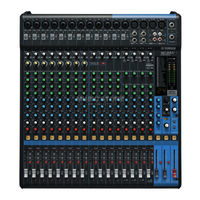
Краткое руководство по эксплуатации
Мы начнем это руководство сподключения пары динамиков и воспроизведения стереосигнала. Следует иметь в виду, что операции и процедуры могут немного меняться взависимости от используемых входных устройств.
|
• Выключатель питания (задняя |
|
панель) |
|
• Гнездо [AC IN] (задняя панель) |
|
MG20XU |
MG16XU |
|||
Шаг 1.Подготовка источника питания
1.Убедитесь в том, что выключатель питания на устройстве установлен в положение «  » (выкл.).
2.Подсоедините штекер прилагаемого кабеля питания к гнезду [AC IN] на задней панели.
3.Вставьте вилку шнура питания в электрическую розетку.
Шаг 2. Установка подключений
1.Полностью выведите вниз все фейдеры и регуляторы [GAIN].
2.Подсоедините микрофоны, инструменты и/или динамики, которые планируется использовать.
Подробную информацию об установке подключений см. в разделах «Примеры настройки» (стр. 12 – 13), «Передняя панель» и «Задняяпанель» (стр. 14 – 15).
MG12XU
Фейдеры
Шаг 3. Включение питания системы
Для предотвращения появления нежелательных шумов из динамиков включайте электропитание устройств в следующем порядке: периферийные устройства (инструменты, микрофоны и т. д.) → микшерный пульт → усилители (или колонки со
встроенным усилителем).
Выключайте электропитание устройств вобратном порядке.
 ВНИМАНИЕ
Каждый раз при использовании микшера обязательно включайте и выключайте питание в порядке, указанном в шаге 3. Если этого не сделать, возможны сильные всплески шумов, которые могут повредить оборудование, ваш слух или и то, и другое.
УВЕДОМЛЕНИЕ
Если используются конденсаторные микрофоны, для которых требуется фантомное питание, включайте переключатель [PHANTOM +48V] на микшере, прежде чем включать усилители или колонки со встроенным усилителем. Подробнее см. на стр. 17. Также перед включением переключателя
[PHANTOM +48V] ознакомьтесь с подробной информацией о нем на стр. 17.
Руководство пользователя MG20XU/MG20/MG16XU/MG16/MG12XU/MG12 9

Краткое руководство по эксплуатации
Шаг 4. Подача звука на динамики
|
Гнездо [PHONES] |
|
|
Регуляторы [GAIN] |
Индикатор уровня [PEAK] |
|
Индикатор уровня |
|
|
Индикатор [PFL] |
|
|
Регулятор [PHONES] |
|
|
Выключатели каналов [ON] |
Выключатель [ON] главного |
|
фейдера [STEREO] |
|
|
Переключатели каналов [ST] |
|
|
Переключатели каналов [PFL] |
Мастер-фейдер [STEREO] |
|
Фейдеры каналов |
1.Включите (  ) переключатели [PFL] для каждого используемого канала.
ПРИМЕЧАНИЕ
•При включении переключателя [PFL] для канала сигнал для этого канала можно отследить через наушники, подключенные к гнезду [Phones]. Уровень сигнала также можно узнать на индикаторе уровня, что позволяет более точно проверить уровни сигнала. После проверки уровней отключите переключатели [PFL].
•Когда переключатель [PFL] включен, под индикатором уровня мигает индикатор [PFL].
2.Играя на инструменте или говоря в микрофон, при помощи регулятора [GAIN] отрегулируйте входной сигнал так, чтобы он проходил через положение «0» (<) на индикаторе уровня лишь
время от времени.
ПРИМЕЧАНИЕ
При подключении портативного аудиопроигрывателя, синтезатора или другого оборудования к каналу стереовхода без регулятора [GAIN] отрегулируйте уровень выхода на подключенном устройстве.
3.Включите (  ) выключатели [ON] для каждого
используемого канала.
4.Включите (  ) переключатели [ST] для каждого используемого канала.
5.Выключите (  ) все переключатели [PFL].
Убедитесь, что индикатор [PFL] под индикатором уровня не горит.
6.Включите (  ) выключатель [ON] главного фейдера [STEREO].
7.Поднимите регулятор мастер-фейдера [STEREO] в положение «0».
8.Установите фейдеры каналов для создания желаемого исходного баланса.
9.Отрегулируйте общую громкость мастерфейдера [STEREO].
Общий уровеньгромкости наушниковустанавливается с помощью регулятора [PHONES].
ПРИМЕЧАНИЕ
Если индикатор уровня [PEAK] загорается часто, немного опустите фейдеры каналов для предотвращения искажения.
Настройка тембра и уровня
|
• Эквалайзер ([HIGH]/[MID]/[LOW]) ……………………………………… |
стр. 18 |
|
• Регуляторы [COMP]………………………………………………………………. |
стр. 17 |
|
• Регуляторы [GAIN]………………………………………………………………… |
стр. 17 |
|
• Фейдеры каналов…………………………………………………………………. |
стр. 19 |
10 Руководство пользователя MG20XU/MG20/MG16XU/MG16/MG12XU/MG12
![]()
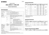
Краткое руководство по эксплуатации
Шаг 5. Использование встроенных эффектов (только модели XU)
Регуляторы [AUX (2, 4)/FX]
*Расположение регуляторов [PROGRAM] и [PARAMETER] в модели MG20XU немного отличается от показанного здесь.
|
Экран |
|
Регулятор [PROGRAM]* |
|
Регулятор [PARAMETER]* |


 Выключатель [ON] для [FX RTN]


 Переключатель [ST] для [FX RTN]
Фейдер [FX RTN]
(На модели MG20XU есть регулятор [FX RTN LEVEL].)
|
1. |
Поверните регулятор [PROGRAM] для выбора |
4. Поднимите регулятор фейдера [FX RTN] в поло- |
|
|
необходимого эффекта, а затем нажмите регу- |
жение «0». |
||
|
лятор, чтобы включить эффект. |
5. Используйте регуляторы [AUX (2, 4)/FX], чтобы |
||
|
Номер программы выбранного эффекта замигает на экра- |
|||
|
настроить глубину эффекта для каждого |
|||
|
не. Подробнуюинформацию о доступных эффектах см. в |
|||
|
канала. |
|||
|
разделе «Программы эффектов» на стр. 33. |
|||
|
2. |
Включите ( ) выключатель [ON] для [FX RTN]. |
6. Используйте регулятор фейдера [FX RTN] для |
|
|
3. |
Включите ( ) переключатель [ST] для [FX RTN]. |
настройки общей глубины выбранного эффекта. |
|
|
Регулятор [PARAMETER] (стр. 23) можно использовать |
|||
|
для настройки таких параметров эффекта, как время |
|||
|
реверберации и задержки. Подробную информацию о |
|||
|
параметрах каждого эффекта, которые можно настроить |
|||
|
при помощи регулятора [PARAMETER], см. на стр. 33. |
Использование реверберации и задержки
Миксы можно улучшить, используя такие встроенные эффекты окружения, как реверберация или задержка.
Время реверберации и задержки
Оптимальное время реверберации для музыкального фрагмента зависит от темпа и плотности музыки, а также общего правила, которое состоит в том, что более длительное время реверберации подходит для баллад, а более короткое – для более ритмичных мелодий. Время задержки можно отрегулировать для передачи повторяющихся ритмических эффектов. Например, при добавлении задержки к вокалу попробуйте установить время задержки на восьмые ноты с точкой ( e. ), соответствующие темпу мелодии.
Уровень реверберации
При многочасовой работе над миксом ваш слух начнет незначительно притупляться. Это может привести к восприятию, при котором дорожки с избыточной обработкой могут звучать как идеальный микс. Чтобы не попасть в эту ловушку, сначала задайте минимальный уровень реверберации, затем постепенно добавляйте ее в микс, пока не услышите разницу. Любое превышение этой разницы обычно становится специальным эффектом или в худшем случае делает звук грязным и нечетким. В целом реверберация не должна преобладать в миксе, поэтому необходимо осмысленно применять этот эффект.
Руководство пользователя MG20XU/MG20/MG16XU/MG16/MG12XU/MG12 11

Настройка
Примеры настройки
1. Усиление звучания для концертного выступления
|
Лицевая панель |
Колонки со встроенным усилителем |
||
|
Электрогитара |
|||
|
Барабан |
(для отслеживания музыкантами) |
||
|
Микрофоны |
Колонки со |
||
|
встроенным |
|||
|
× 2 |
|||
|
Бас-гитара |
усилителем |
||
|
(основные) |
|||
|
Микрофоны |
Синтезатор |
||
|
× 3 |
|||
|
Электроакустичес |
|||
|
кая гитара |
DI
К гнездам моновхода можно подключить разъемы типа XLR и разъемы для наушников.
Задняя панель
Компьютер (для воспроизведения и/или записи музыки)
(Гнездо [USB 2.0] есть только в моделях XU.)
ПРИМЕЧАНИЕ
В моделях MG20XU/MG20 гнезда [SEND], [GROUP OUT], [MONITOR OUT] и [STEREO OUT] находятся на задней панели.
Педальный
переключатель (YAMAHA FC5)
(Гнездо [FOOT SW] есть только в моделях XU.)
Портативный
аудиопроигрыватель
Наушники
12 Руководство пользователя MG20XU/MG20/MG16XU/MG16/MG12XU/MG12
 Loading…
 Loading…
MG12-16_E.book Page 1 Monday, May 26, 2003 1:14 PM
MIXING CONSOLE
Owner’s Manual
MG16/4
MG12/4
Making the Most Of Your Mixer
Pages 6 to 17
E
MG12-16_E.book Page 2 Monday, May 26, 2003 1:14 PM
Precautions
—For safe operation—
WARNING
●
Installation
●
●
●
●
Connect this unit’s AC power adaptor only to an AC outlet of the
type stated in this Owner’s Manual or as marked on the unit.
Failure to do so is a fire and electrical shock hazard.
Do not allow water to enter this unit or allow the unit to become
wet. Fire or electrical shock may result.
Do not place a container with liquid or small metal objects on
top of this unit. Liquid or metal objects inside this unit are a fire
and electrical shock hazard.
Do not place heavy objects, including this unit, on top of the
power cord. A damaged power cord is a fire and electrical shock
hazard. In particular, be careful not to place heavy objects on a
power cord covered by a carpet.
●
●
In case an abnormality occurs during operation
●
●
Operation
●
●
●
Do not scratch, bend, twist, pull, or heat the power cord. A damaged power cord is a fire and electrical shock hazard.
Do not remove the unit’s cover. You could receive an electrical
shock. If you think internal inspection, maintenance, or repair is
necessary, contact your dealer.
Do not modify the unit. Doing so is a fire and electrical shock
hazard.
If lightning begins to occur, turn off the power switch of the unit
as soon as possible, and unplug the power plug from the electrical outlet.
If there is a possibility of lightning, do not touch the power plug
if it is still connected. Doing so may be an electrical shock hazard.
Use only the included AC power adaptor (PA-20) for this unit.
Using other types may be a fire and electrical shock hazard.
●
If the power cord is damaged (i.e., cut or a bare wire is exposed),
ask your dealer for a replacement. Using the unit with a damaged
power cord is a fire and electrical shock hazard.
Should this unit and AC adaptor be dropped or the cabinet be
damaged, turn the power switch off, remove the power plug from
the AC outlet, and contact your dealer. If you continue using the
unit without heeding this instruction, fire or electrical shock may
result.
If you notice any abnormality, such as smoke, odor, or noise, or
if a foreign object or liquid gets inside the unit, turn it off immediately. Remove the power plug from the AC outlet. Consult your
dealer for repair. Using the unit in this condition is a fire and
electrical shock hazard.
CAUTION
Installation
●
●
●
2
Keep this unit away from the following locations:
- Locations exposed to oil splashes or steam, such as near cooking stoves, humidifiers, etc.
- Unstable surfaces, such as a wobbly table or slope.
- Locations exposed to excessive heat, such as inside a car with
all the windows closed, or places that receive direct sunlight.
- Locations subject to excessive humidity or dust accumulation.
Hold the power plug when disconnecting it from an AC outlet.
Never pull the cord. A damaged power cord is a potential fire and
electrical shock hazard.
Do not touch the power plug with wet hands. Doing so is a
potential electrical shock hazard.
MG16/4, MG12/4
●
To relocate the unit, turn the power switch off, remove the power
plug from the AC outlet, and remove all connecting cables. Damaged cables may cause fire or electrical shock.
Operation
●
●
Do not cover or wrap the AC power adaptor with a cloth or blanket. Heat may build up under the cloth or blanket, melting the
case, or causing fire. Use only in a well-ventilated environment.
If you know you will not use this unit for a log period of time,
such as when going on vacation, remove the power plug from the
AC outlet. Leaving it connected is a potential fire hazard.
MG12-16_E.book Page 3 Monday, May 26, 2003 1:14 PM
Precautions
—For correct operation —
Connector pin assignments
●
●
XLR-type connectors are wired as follows: pin 1: ground, pin 2:
hot (+), and pin 3: cold (–).
Insert TRS phone jacks are wired as follows: sleeve: ground, tip:
send, and ring: return.
Influence on cell phone usage
●
Using a cell phone (mobile telephone) near this unit may induce
noise. If noise occurs, use the telephone away from the unit.
Replacing abrasive parts
●
The performance of components with moving contacts, such
switches, rotary controls, faders, and connectors, deteriorates
over time. The rate of deterioration depends on the operating
environment and is unavoidable. Consult your dealer about
replacing defective components.
●
●
Always turn the power off when the mixer is not in use.
Even when the power switch is in the “STANDBY” position, electricity is still flowing to the mixer at the minimum level. When you are
not using the mixer for a long time, make sure you unplug the AC power adaptor from the wall AC outlet.
Copying of the commercially available music data and/or digital audio files is strictly prohibited except for your personal use.
Illustration examples shown herein are for explanatory purposes only, and may not match actual appearance during operation.
The company names and product names in this Owner’s Manual are the trademarks or registered trademarks of their respective companies.
IMPORTANT NOTICE FOR THE UNITED KINGDOM
Connecting the Plug and Cord
IMPORTANT. The wires in this mains lead are coloured in accordance with the following code:
BLUE
: NEUTRAL
BROWN : LIVE
As the colours of the wires in the mains lead of this apparatus may not correspond with the coloured makings identifying the terminals in your
plug proceed as follows:
The wire which is coloured BLUE must be connected to the terminal which is marked with the letter N or coloured BLACK.
The wire which is coloured BROWN must be connected to the terminal which is marked with the letter L or coloured RED.
Making sure that neither core is connected to the earth terminal of the three pin plug.
• This applies only to products distributed by Yamaha-Kemble Music (U.K.) Ltd. (2 wires)
MG16/4, MG12/4
3
MG12-16_E.book Page 4 Monday, May 26, 2003 1:14 PM
Introduction
Thank you for your purchase of the YAMAHA MG16/4 or MG12/4 mixing console. This mixing
console combines ease of operation with support for multiple usage environments, and is
ideal for SR setups, installed systems, and many other such applications.
Please read through this Owner’s Manual carefully before beginning use, so that you will be
able to take full advantage of the mixer’s superlative features and enjoy trouble-free operation
for years to come.
Features
Contents
Introduction ............................................................... 4
●
The MG16/4 provides 16 input channels that can assign to Stereo or Group output.
●
The MG12/4 provides 12 input channels that can assign to Stereo or Group output.
●
The monitor includes a convenient C-R OUT jack. This jack can
be used to monitor the main Stereo output, the PFL signal, or the
Group 1-2 signals.
Before Turning on the Mixer ................................. 5
The mixer includes dual AUX SEND jacks and a single
RETURN jack. The two independent AUX buses may be used as
sends to external effectors and monitor systems.
Making the Most Of Your Mixer ................................. 6
●
●
Phantom power supply enables easy connection to condenser
microphones that run on external power.
●
The mixer provides channel-specific INSERT I/O jacks for input
channels 1 to 8 (MG16/4) or 1 to 4 (MG12/4). These jacks make
it possible to insert different effectors into different channels.
●
Input channels 1 to 8, 9/10, and 11/12 (MG16/4), and 1 to 4, 5/6,
and 7/8 (MG12/4) are each equipped with both an XLR mic
input jack and a TRS phone-type line jack. Input channels 13/14
and 15/16 (MG16/4), and 9/10 and 11/12 (MG12/4) are each
equipped with both a TRS line input jack and an RCA line input
jack. This wide assortment of connectors enables connection to
many different devices, from microphones to line-level devices
to stereo-output synthesizers.
Features ............................................................... 4
Contents .............................................................. 4
Turning the Power On .......................................... 5
1 A Place For Everything and Everything
In Its Place ....................................................... 7
2 Where Your Signal Goes Once It’s Inside
the Box .......................................................... 10
3 The First Steps in Achieving Great Sound .... 11
4 External Effects, Monitor Mixes,
and Groups .................................................... 13
5 Making Better Mixes....................................... 16
Front & Rear Panels ................................................ 18
Channel Control Section .................................... 18
Master Control Section ...................................... 20
Rear Input/Output Section ................................. 22
Setting Up ............................................................... 24
Setup Procedure ................................................ 24
Setup Examples ................................................ 24
Rack Mounting ................................................... 26
Appendix ................................................................. 27
Specifications .................................................... 27
Dimensional Diagrams ....................................... 29
Block Diagram and Level Diagram .................... 30
4
MG16/4, MG12/4
MG12-16_E.book Page 5 Monday, May 26, 2003 1:14 PM
Introduction
Before Turning on the Mixer
(1) Be sure that the mixer’s power switch is in the STANDBY
position.
Use only the PA-20 adaptor included with this mixer.
Use of a different adaptor may result in equipment
damage, overheating, or fire.
(2) Connect the power adaptor to the AC ADAPTOR IN connector ( 1) on the rear of the mixer, and then turn the fastening ring clockwise ( 2) to secure the connection.
Turning the Power On
Press the mixer’s power switch to the ON position. When you are
ready to turn the power off, press the power switch to the
STANDBY position.
Note that trace current continues to flow while the
switch is in the STANDBY position. If you do not plan
to use the mixer again for a long while, please be sure
to unplug the adaptor from the wall outlet.
2
1
(3) Plug the power adaptor into a standard household power outlet.
• Be sure to unplug the adaptor from the outlet when
not using the mixer, or when there are lightning
storms in the area.
• To avoid generating unwanted noise, make sure
there is adequate distance between the power
adaptor and the mixer.
MG16/4, MG12/4
5
MG12-16_E.book Page 6 Monday, May 26, 2003 1:14 PM
Making the Most Of Your Mixer
An Introduction
You’ve got yourself a mixer and now you’re ready to use it.
Just plug everything in, twiddle the controls, and away you go … right?
Well, if you’ve done this before you won’t have any problems, but if this is
the first time you’ve ever used a mixer you might want to read through this
little tutorial and pick up a few basics that will help you get better
performance and make better mixes.
6
MG16/4, MG12/4
MG12-16_E.book Page 7 Monday, May 26, 2003 1:14 PM
Making the Most Of Your Mixer
1
A Place For Everything and Everything In Its Place
1-1. A Plethora Of Connectors—What Goes Where?
Questions you’re likely to encounter when setting up a system for the first time might include “Why all
these different types of connectors on the back of my mixer?” and “What’s the difference?”.
Let’s start by taking a look at the most common connector types.
The Venerable RCA Pin Jack
White
Red
This is the “consumer connector,” and the one that has been most commonly used
on home audio gear for many years. Also known as “phono” jacks (short for
”phonogram”), but the term isn’t used much these days—besides, it’s too easily
confusable with “phone” jacks, below. RCA pin jacks are always unbalanced, and
generally carry a line-level signal at –10 dB, nominal. You’re most likely to use this
type of connector when connecting a CD player or other home audio type source
to your mixer, or when connecting the output of your mixer to a cassette recorder
or similar gear.
The Versatile Phone Jack
The name “phone jack” arose simply because this configuration was first
used in telephone switchboards. Phone jacks can be tricky because you
can’t always tell what type of signal they’re designed to handle just by
looking at them. It could be unbalanced mono, unbalanced stereo,
balanced mono, or an insert patch point. The connector’s label will
usually tell you what type of signal it handles, as will the owner’s manual
(you do keep your manuals in a safe place, don’t you?). A phone jack that
is set up to handle balanced signals is also often referred to as a “TRS”
phone jack. “TRS” stands for Tip-Ring-Sleeve, which describes the
configuration of the phone plug used.
Stereo/TRS phone plug
Mono phone plug
The Sturdy XLR
Male
This type of connector is generally referred to as “XLR-type,” and almost always
carries a balanced signal. If the corresponding circuitry is designed properly,
however, XLR-type connectors will also handle unbalanced signals with no
problem. Microphone cables usually have this type of connector, as do the inputs
and outputs of most professional audio gear.
Female
MG16/4, MG12/4
7
MG12-16_E.book Page 8 Monday, May 26, 2003 1:14 PM
Making the Most Of Your Mixer
1-2. Balanced, Unbalanced—What’s the Difference?
In a word: “noise.” The whole point of balanced lines is noise rejection, and it’s something they’re very
good at. Any length of wire will act as an antenna to pick up the random electromagnetic radiation we’re
constantly surrounded by: radio and TV signals as well as spurious electromagnetic noise generated by
power lines, motors, electric appliances, computer monitors, and a variety of other sources. The longer
the wire, the more noise it is likely to pick up. That’s why balanced lines are the best choice for long
cable runs. If your “studio” is basically confined to your desktop and all connections are no more than a
meter or two in length, then unbalanced lines are fine—unless you’re surrounded by extremely high levels of electromagnetic noise. Another place balanced lines are almost always used is in microphone
cables. The reason for this is that the output signal from most microphones is very small, so even a tiny
amount of noise will be relatively large, and will be amplified to an alarming degree in the mixer’s highgain head amplifier.
To summarize:
Microphones:
Short line-level runs:
Long line-level runs:
Use balanced lines.
Unbalanced lines are fine if you’re in a relatively noise-free environment.
The ambient electromagnetic noise level will be the ultimate deciding factor, but
balanced is best.
■ How Do Balanced Lines Reject Noise?
** Skip this section if technical details make you queasy. **
Balanced lines work on the principle of “phase cancellation”: if you add two identical signals out of
phase (i.e. one signal is inverted so its peaks coincide with the troughs in the other signal), the result is …
nothing. A flat line. The signals cancel each other out.
Normal-phase signal.
No signal.
(Phase cancellation)
Reverse-phase signal.
A balanced cable has three conductors:
1) A ground conductor which carries no signal, just the “ground” or “0” reference against which the
signal in the other conductors fluctuates.
2) A “hot” or “+” conductor which carries the normal-phase audio signal.
3) A “cold” or “–” conductor which carries the reverse-phase audio signal.
While the desired audio signals in the hot and cold conductors are out of phase, any noise induced in
the line will be exactly the same in both conductors, and thus in phase. The trick is that the phase of
one signal is reversed at the receiving end of the line so that the desired audio signals become inphase, and the induced noise suddenly finds itself out of phase. The out-of-phase noise signal is effectively canceled while the audio signal is left intact. Clever, eh?
Normal-phase signal
+ normal-phase noise.
Desired signal
with no noise.
Normal-phase signal
+ reverse-phase noise.
8
MG16/4, MG12/4
MG12-16_E.book Page 9 Monday, May 26, 2003 1:14 PM
Making the Most Of Your Mixer
1-3. Signal Levels—Decibel Do’s and Don’ts
From the moment you start dealing with things audio, you’ll have to deal with the term “decibel” and its
abbreviation, “dB”. Things can get confusing because decibels are a very versatile unit of measure used
to describe acoustic sound pressure levels as well as electronic signal levels. To make matters worse there
are a number of variations: dBu, dBV, dBm. Fortunately, you don’t need to be an expert to make things
work. Here are a few basics you should keep in mind:
● “Consumer” gear (such as home audio equipment) usually has line inputs and outputs with a nomi-
nal (average) level of –10 dB.
● Professional audio gear usually has line inputs and outputs with a nominal level of +4 dB.
● You should always feed –10 dB inputs with a –10 dB signal. If you feed a +4 dB signal into a –10 dB
input you are likely to overload the input.
● You should always feed +4 dB inputs with a +4 dB signal. A –10 dB signal is too small for a +4 dB
input, and will result in less-than-optimum performance.
● Many professional and semi-professional devices have level switches on the inputs and/or outputs
that let you select –10 or +4 dB. Be sure to set these switches to match the level of the connected
equipment.
● Inputs that feature a “Gain” control—such as the mono-channel inputs on your Yamaha mixer—will
accept a very wide range of input levels because the control can be used to match the input’s sensitivity to the signal. More on this later.
MG16/4, MG12/4
9
MG12-16_E.book Page 10 Monday, May 26, 2003 1:14 PM
Making the Most Of Your Mixer
2
Where Your Signal Goes Once It’s Inside the Box
At first glance the block diagram of even a modest mixer can look like a space-station schematic. In reality,
block diagrams are a great aid in understanding how the signal flows in any mixer. Here’s a greatly simplified
block diagram of a generic mixer to help you become familiar with the way these things work.
2-1. Greatly Simplified Mixer Block Diagram
Input Channel
Master Section
Signals from the mixer’s
other input channels (if
they are assigned to this
master output or “bus”).
1
2
3
■ Input Channel
1 Head Amp
The very first stage in any mixer, and
usually the only stage with significant
“gain” or “amplification.” The head
amp has a “gain” control that adjusts
the mixer’s input sensitivity to match the
level of the source. Small signals (e.g.
mics) are amplified, and large signals
are attenuated.
2 Equalizer
Could be simple bass and treble controls or a full-blown 4-band parametric
EQ. When boost is applied the EQ stage
also has gain. You can actually overload
the input channel by applying too much
EQ boost. It’s usually better to cut than
boost.
10
MG16/4, MG12/4
4
5
3 Channel Peak LED & Fader
The channel peak LED is your most
valuable tool for setting the input “gain”
control for optimum performance. Note
that it is located after the head amp and
EQ stage.
■ Master Section
4 Summing Amplifier
This is where the actual “mixing” takes
place. Signals from all of the mixer’s
input channels are “summed” (mixed)
together here.
5 Master Fader & Level Meter
A stereo, mono, or bus master fader and
the mixer’s main output level meter.
There could be several master faders
depending on the design of the mixer—
i.e. the number of buses or outputs it
provides.
MG12-16_E.book Page 11 Monday, May 26, 2003 1:14 PM
Making the Most Of Your Mixer
3
The First Steps in Achieving Great Sound
Before you even consider EQ and effects, or even the overall mix, it is important to make sure that levels are
properly set for each individual source. This can’t be stressed enough—initial level setup is vitally important for
achieving optimum performance from your mixer! Here’s why … and how.
3-1. The Head Amplifier “Gain” Control Is the Key!
Let’s review our simplified mixer block diagram:
Each and every “stage” in the mixer’s signal path will add a certain amount of noise to the signal: the
head amp, the EQ stage, the summing amplifier, and the other buffer and gain stages that exist in the
actual mixer circuit (this applies to analog mixers in particular). The thing to keep in mind is that the
amount of noise added by each stage is usually not dependent to any significant degree on the level of
the audio signal passing through the circuit. This means that the bigger the desired signal, the smaller the
added noise will be in relation to it. In tech-speak this gives us a better “signal-to-noise ratio”—often
abbreviated as “S/N ratio.” All of this leads to the following basic rule:
To achieve the best overall system S/N ratio, amplify the input to the desired average
level as early as possible in the signal path.
In our mixer, that means the head amplifier. If you don’t get the signal up to the desired level at the head
amplifier stage, you will need to apply more gain at later stages, which will only amplify the noise contributed by the preceding stages. Just remember that too much initial gain is bad too, because it will overload our channel circuitry and cause clipping.
MG16/4, MG12/4
11
MG12-16_E.book Page 12 Monday, May 26, 2003 1:14 PM
Making the Most Of Your Mixer
3-2. Level Setup Procedure For Optimum Performance
Now that we know what we have to do, how do we do it? If you take another quick look at the mixer
block diagram you’ll notice that there’s a peak indicator located right after the head amplifier and EQ
stages, and therein lays our answer! Although the exact procedure you use will depend on the type of
mixer you use and the application, as well as your personal preferences, here’s a general outline:
1
Start by setting all level controls to their minimum: master faders, group faders (if provided), channel faders, and input gain
controls. Also make sure that no EQ is applied (no boost or
cut), and that all effects and dynamic processors included in
the system are defeated or bypassed.
2
Apply the source signal to each channel one at a time: have
singers sing, players play, and playback devices play back at
the loudest expected level. Gradually turn up the input gain
control while the signal is being applied to the corresponding
channel until the peak indicator begins to flash, then back off
a little so that the peak indicator flashes only occasionally.
Repeat for each active channel.
3
Raise your master fader(s)—and group faders if available—to
their nominal levels (this will be the “0” markings on the fader
scale).
4
Now, with all sources playing, you can raise the channel faders and set up an initial rough mix.
That’s basically all there is to it. But do keep your eyes on the main output level meters while setting up
the mix to be sure you don’t stay in the “peak zone” all the time. If the output level meters are peaking
constantly you will need to lower the channel faders until the overall program falls within a good range—
and this will depend on the “dynamic range” of your program material.
12
MG16/4, MG12/4
MG12-16_E.book Page 13 Monday, May 26, 2003 1:14 PM
Making the Most Of Your Mixer
4
External Effects, Monitor Mixes, and Groups
4-1. AUX Buses For Monitor Sends and
Overall Effects
There are a number of reasons why you might
want to “tap” the signal flowing through your
mixer at some point before the main outputs: the
two most common being 1) to create a monitor
mix that is separate from the main mix, and 2) to
process the signal via an external effect unit and
then bring it back into the mix. Both of these functions, and more, can be handled by the mixer’s
AUX (Auxiliary) buses and level controls. If the
mixer has two AUX buses, then it can handle both
functions at the same time. Larger mixing consoles can have 6, 8, or even more auxiliary buses
to handle a variety of monitoring and processing
needs.
Pre/Post—What’s the difference?
pre
post
A “pre-fader” signal is taken
from a point before the
channel fader, so the send
level is affected only by the
AUX send level control and
not by the channel fader.
A “post-fader” signal is
taken from a point after the
channel fader, so its level
will be affected by both the
AUX send level control and
the channel fader.
Pre-fader sends are most
commonly used to provide
monitor mixes.
Post-fader sends are most
commonly used in conjunction with the mixer’s AUX or
effect returns for external
effect processing.
Using the AUX buses and level controls is pretty
straightforward. The only thing you need to consider is whether you need a “pre-fader” or “postfader” send. AUX sends often feature a switch that
allows you to configure them for pre- or postfader operation.
Pre-fader send for a monitor mix. The send signal is fed to the monitor power amplifier and speaker system.
The channel fader does not affect the send level so the monitor mix remains independent of the main mix. No
return signal is used in this case.
Channel
Fader
Master
Fader
AUX Send
Level
AUX Send Level
AUX Return Level
Post-fader send for external effects processing. The send signal is fed to the external effect unit—a reverb
unit, for example—and the output from the effect unit is returned to the AUX Return jack and mixed back into the
main program. The send level is affected by the channel fader so the effect level always remains in proportion to
the channel signal.
MG16/4, MG12/4
13
MG12-16_E.book Page 14 Monday, May 26, 2003 1:14 PM
Making the Most Of Your Mixer
4-2. Using Groups
Group buses and faders can greatly simplify the mixing process—particularly in live situations in which
changes have to be made as quickly as possible. If you have a group of channels that need to be adjusted
all together while maintaining their relative levels, grouping is the way to go. Simply assign the group to a
group bus, and make sure that group is also assigned to the main program bus. Then you can adjust the
overall level of the group using a single group fader, rather than having to attempt to control multiple
channels faders simultaneously.
Group buses usually also have their own outputs, so you can send the group signal to a different external
destination from the main mix.
A group of channels whose levels need to
maintain the same relationship—a drum mix, for
example—can be assigned to a group bus.
Usually the group bus signal can be output
independently via “Group” outputs, or it can be
assigned to the main program (stereo) bus to be
mixed in with the main stereo program.
Channel faders Assigned to Group
(Controlled As a Group)
Group
Fader
Once the mix between the channels assigned to
the group is established via the channel faders,
the overall level of the entire group can be
conveniently adjusted via a single group fader.
Channel faders Assigned to Stereo
(Controlled Individually)
Stereo
Master
Fader
14
MG16/4, MG12/4
MG12-16_E.book Page 15 Monday, May 26, 2003 1:14 PM
Making the Most Of Your Mixer
4-3. Channel Inserts for Channel-specific Processing
Another way to get the mixer’s signal outside the box is to use the channel inserts. The channel inserts are
almost always located before the channel fader and, when used, actually “break” the mixer’s internal signal path. Unlike the AUX sends and returns, the channel insert only applies to the corresponding channel. Channel inserts are most commonly used for applying a dynamics processor such as a compressor or
limiter to a specific channel—although they can be used with just about any type of in/out processor.
Channel
Fader
When a plug is inserted into the channel insert jack, the internal signal path is interrupted and sent outside the mixer for
external processing.
Channel insert jacks must be used with a special insert cable that has a TRS phone jack on one end and
mono phone jacks on the split “Y” end. One of the mono phone jacks carries the “send” signal to be fed
to the input of the external processor, and the other carries the “return” signal from the output of the processor.
To the input jack of the
external processor
To the INSERT I/O jack
Sleeve
Sleeve
Ring
Tip
Tip
To the output jack of
the external processor
MG16/4, MG12/4
15
MG12-16_E.book Page 16 Monday, May 26, 2003 1:14 PM
Making the Most Of Your Mixer
5
Making Better Mixes
5-1. Approaching the Mix—Where Do
You Start?
Mixing is easy, right? Just move the faders around
until it sounds right? Well, you can do it that way,
but a more systematic approach that is suited to
the material you’re mixing will produce much
better results, and faster. There are no rules, and
you’ll probably end up developing a system that
works best for you. But the key is to develop a
system rather than working haphazardly. Here are
a few ideas to get you started:
Faders Down
It might sound overly simple, but it is usually a
good idea to start with all channel faders off—all
the way down. It’s also possible to start with all
faders at their nominal settings, but it’s too easy to
lose perspective with this approach. Start with all
faders down, then bring them up one by one to fill
out the mix. But which channel should you start
with?
Example1:
Vocal Ballad Backed by Piano Trio
What are you mixing? Is it a song in which the
vocals are the most important element? If so you
might want to build the mix around the vocals.
This means bringing the vocal channel up to
nominal first (if your level setup procedure has
been done properly this will be a good starting
point), and then adding the other instruments.
What you add next will depend on the type of
material you are working with and your approach
to it. If the vocals are backed by a piano trio and
the song is a ballad, for example, you might want
to bring in the piano next and get the vocal/piano
relationship just right, then bring in the bass and
drums to support the overall sound.
Example2:
Funky R&B Groove
The approach will be totally different if you’re
mixing a funky R&B number that centers on the
groove. In this case most engineers will start with
the drums, and then add the bass. The relationship between the drums and bass is extremely
important to achieve the “drive” or groove the
music rides on. Pay particular attention to how
the bass works with the kick (bass drum). They
should almost sound like a single instrument—
with the kick supplying the punch and the bass
supplying the pitch. Once again, there are no
rules, but these are concepts that have been
proven to work well.
16
MG16/4, MG12/4
Music First—Then Mix
In any case, the music comes first. Think about
the music and let it guide the mix, rather than trying to do things the other way around. What is the
music saying and what instrument or technique is
being used to drive the message? That’s where the
focus of your mix should be. You’re using a hightech tool to do the mixing, but the mix itself is as
much art as the music. Approach it that way and
your mixes will become a vital part of the music.
5-2. Panning For Cleaner Mixes
Not only does the way you pan your individual
channels determine where the instruments appear
in the stereo sound field, but it is also vital to give
each instrument it’s own “space” so that it doesn’t
conflict with other instruments. Unlike live sound
in a real acoustic space, recorded stereo sound is
basically 2-dimensional (although some types of
surround sound are actually very 3-dimensional),
and instruments positioned right on top of each
other will often get in each other’s way—particularly if they are in the same frequency range or
have a similar sound.
MG12-16_E.book Page 17 Monday, May 26, 2003 1:14 PM
Making the Most Of Your Mixer
Spread them Out!
Position your instruments so they have room to
“breathe,” and connect in the most musical way
with other instruments. Sometimes, however,
you’ll want to deliberately pan sounds close
together, or even right on top of one another, to
emphasize their relationship. There are no hardand-fast rules. Normally (but this is not a rule),
bass and lead vocals will be panned to center, as
will the kick drum if the drums are in stereo.
5-3. To EQ Or Not To EQ
In general: less is better. There are many situations
in which you’ll need to cut certain frequency
ranges, but use boost sparingly, and with caution.
Proper use of EQ can eliminate interference
between instruments in a mix and give the overall
sound better definition. Bad EQ—and most commonly bad boost—just sounds terrible.
Cut For a Cleaner Mix
For example: cymbals have a lot of energy in the
mid and low frequency ranges that you don’t
really perceive as musical sound, but which can
interfere with the clarity of other instruments in
these ranges. You can basically turn the low EQ
on cymbal channels all the way down without
changing the way they sound in the mix. You’ll
hear the difference, however, in the way the mix
sounds more “spacious,” and instruments in the
lower ranges will have better definition. Surprisingly enough, piano also has an incredibly powerful low end that can benefit from a bit of lowfrequency roll-off to let other instruments—notably drums and bass—do their jobs more effectively. Naturally you won’t want to do this if the
piano is playing solo.
The reverse applies to kick drums and bass guitars: you can often roll off the high end to create
more space in the mix without compromising the
character of the instruments. You’ll have to use
your ears, though, because each instrument is different and sometimes you’ll want the “snap” of a
bass guitar, for example, to come through.
Boost With Caution
If you’re trying to create special or unusual
effects, go ahead and boost away as much as you
like. But if you’re just trying to achieve a goodsounding mix, boost only in very small increments. A tiny boost in the midrange can give
vocals more presence, or a touch of high boost
can give certain instruments more “air.” Listen,
and if things don’t sound clear and clean try using
cut to remove frequencies that are cluttering up
the mix rather than trying to boost the mix into
clarity.
One of the biggest problems with too much boost
is that it adds gain to the signal, increasing noise
and potentially overloading the subsequent circuitry.
5-4. Ambience
Judicious application of reverb and/or delay via
the mixer’s AUX busses can really polish a mix,
but too much can “wash out” the mix and reduce
overall clarity. The way you set up your reverb
sound can make a huge difference in the way it
meshes with the mix.
Reverb/Delay Time
Different reverb/delay units offer different capabilities, but most offer some means of adjusting the
reverb time. A little extra time spent matching the
reverb time to the music being mixed can mean
the difference between great and merely average
sound. The reverb time you choose will depend
to a great degree on the tempo and “density” of
the mix at hand. Slower tempos and lower densities (i.e. sparser mixes with less sonic activity) can
sound good with relatively long reverb times. But
long reverb times can completely wash out a
faster more active piece of music. Similar principles applies to delay.
Reverb Tone
How “bright” or “bassy” a reverb sound is also
has a huge impact on the sound of your mix. Different reverb units offer different means of controlling this—balance between the high- and lowfrequency reverb times, simple EQ, and others. A
reverb that is too bright will not only sound unnatural, but it will probably get in the way of delicate
highs you want to come through in your mix. If
you find yourself hearing more high-end reverb
than mix detail, try reducing the brightness of the
reverb sound. This will allow you to get full-bodied ambience without compromising clarity.
Reverb Level
It’s amazing how quickly your ears can lose perspective and fool you into believing that a totally
washed-out mix sounds perfectly fine. To avoid
falling into this trap start with reverb level all the
way down, then gradually bring the reverb into
the mix until you can just hear the difference. Any
more than this normally becomes a “special
effect.” You don’t want reverb to dominate the
mix unless you are trying to create the effect of a
band in a cave—which is a perfectly legitimate
creative goal if that’s the sort of thing you’re aiming for.
MG16/4, MG12/4
17
MG12-16_E.book Page 18 Monday, May 26, 2003 1:14 PM
Front & Rear Panels
1 GAIN Control
Channel Control Section
Channels
1 to 8 (MG16/4)
1 to 4 (MG12/4)
(Monaural)
Channels
9/10 and 11/12
(MG16/4)
5/6 and 7/8
(MG12/4)
(Stereo)
Adjusts the input signal level.
To get the best balance between the S/N ratio and the dynamic
range, adjust the level so that the peak indicator (2) comes on
only at about maximum input level.
Channels
13/14 and 15/16
(MG16/4)
9/10 and 11/12
(MG12/4)
(Stereo)
The –60 to –16 scale indicates the MIC input adjustment level.
The –34 to +10 scale indicates the LINE input adjustment
level.
2 PEAK Indicator
Detects the peak level of the post-EQ signal, and lights up red
when the level reaches 3 dB below the clipping level. For
XLR-equipped stereo input channels (9/10 and 11/12 on the
MG16/4; 5/6 and 7/8 on the MG12/4), detects both post-EQ
and post-mic-amp peak levels, and lights red if either of these
levels reaches 3 dB below the clipping level.
1
3
2
3
Switch (High Pass Filter)
This switch toggles the HPF on or off. To turn the HPF on,
press the switch in (
). The HPF cuts frequencies below
80 Hz. (But note that regardless of the switch setting, the mixer
does not apply this HPF to the line inputs of stereo input channels.)
4
5
5
6
6
7
7
7
8
8
8
9
9
0
4 Equalizer (HIGH, MID, and LOW)
5
6
9
0
0
This three-band equalizer adjusts the channel’s high, mid, and
low frequency bands. Setting the knob to the
position produces a flat frequency response. Turning the knob to the right
boosts the corresponding frequency band, while turning to the
left attenuates the band. The following table shows the EQ
type, base frequency, and maximum cut/boost for each of the
three bands.
Band
Type
Base Frequency Maximum Cut/Boost
HIGH
Shelving
10 kHz
MID
Peaking
2.5 kHz
LOW
Shelving
100 Hz
±15 dB
5 AUX1 and AUX2 Controls
The AUX1 knob controls the signal level that the channel sends
to the AUX1 bus; the AUX2 knob controls the signal level to
the AUX2 bus. The knob should generally be set close to the
position.
If you are using stereo channels, the signals from the L (odd)
and R (even) channels are mixed and sent to the AUX1 and
AUX2 buses.
A
A
Note: Within this manual, all panel illustrations show the
MG16/4 panel.
18
MG16/4, MG12/4
A
NOTE
Allows you to output the signal to the buses regardless of the setting of the ST switch 8.
MG12-16_E.book Page 19 Monday, May 26, 2003 1:14 PM
Front & Rear Panels
6 PRE Switch
Selects whether the pre-fader or the post-fader signal is fed to
the AUX1 bus. If you set the switch on (
), the mixer sends
the pre-fader signal (the signal prior to passage though channel
fader A) to the AUX1 bus, so that AUX1 output is not affected
by the fader. If you set the switch off (
post-fader signal to the AUX1 bus.
) the mixer sends the
Note that this switch applies to AUX1 only. The signal to the
AUX2 bus always passes through the channel fader first.
7 PAN Control (MG16/4: CHs 1 to 8.
MG12/4: 1 to 4.)
PAN/BAL Control (MG16/4: 9/10 and 11/12.
MG12/4: 5/6 and 7/8.)
BAL Control (MG16/4: 13/14 and 15/16.
MG12/4: 9/10 and 11/12.)
The PAN control determines the positioning of the channel’s
signal on the Group 1 and 2 buses or on the Stereo L and R
buses.
The BAL control knob sets the balance between left and right
channels. Signals into to the L input (odd channel) feed to the
Group 1 bus or to the Stereo L bus; signals into the R input
(even channel) feed to the Group 2 bus or the Stereo R bus.
NOTE
8
On channels where this knob provides both PAN
and BAL controls (9/10 and 11/12 on the MG16/4;
5/6 and 7/8 on the MG12/4), the knob operates as a
PAN control if you are inputting through the MIC
jack or into the L (MONO) input only, and operates
as a BAL control if you are inputting into both L and
R inputs.
ST Switch
This switch assigns the channel’s signal to the Stereo L and R
buses. To send the signal to the Stereo bus, set the switch on by
pressing it in (
). The switch lights up orange to indicate that
it is on.
9 PFL (Pre-Fader Listen) Switch
This switch lets you monitor the channel’s pre-fader signal. To
set the switch on, press it in (
) so that it lights up. When the
switch is on, the mixer outputs the channel’s pre-fader signal to
the PHONES and C-R OUT jacks, for monitoring.
0 GROUP Switch
Use this switch to assign the channel’s signal to the Group output. Press the switch in (
) to output the signal to the Group
1 and 2 buses.
NOTE
Allows you to output the signal to the buses regardless of the setting of the ST switch 8.
A Channel Fader
Adjusts the output level of the signal being input to the channel. Use these faders to adjust the volume balance among the
various channels.
NOTE
To reduce noise, set the fader sliders for unused
channels all the way down.
MG16/4, MG12/4
19
MG12-16.fm
Page 20
Thursday, December 11, 2003
9:03 AM
Front & Rear Panels
1 ST Master Fader
Master Control Section
Adjusts the signal level to the ST OUT jacks.
2 GROUP 1-2 Fader
B
6
7
Adjusts the signal level to the GROUP OUT 1 and GROUP
OUT 2 jacks.
3 TO ST Switch
A
If this switch is on (
), the mixer sends the signals processed
by the GROUP 1-2 fader (2) onto the Stereo bus. The Group 1
signal goes to Stereo L and the Group 2 signal goes to Stereo
R.
4 Master SEND (AUX1 and AUX2 Controls)
Adjust the signal level, respectively. These are the signals that
are output to the AUX1 and AUX2 SEND jacks.
0
5 RETURN (AUX1, AUX2, and ST Controls)
• AUX1 and AUX2 Controls
Adjust the level of the mixed L/R signal sent from the
RETURN jacks (L (MONO) and R) to the AUX1 and AUX2
buses.
• ST Control
Adjust the level of the signal sent from the RETURN jacks (L
(MONO) and R) to the Stereo bus.
9
4
NOTE
8
5
6 2TR IN Control
Adjusts the level of the signal sent from the 2TR IN jack to the
Stereo bus.
3
2
If you supply a signal to the RETURN L (MONO)
jack only, the mixer outputs the identical signal to
both the L and R Stereo buses.
1
7 PHANTOM +48 V Switch
This switch toggles phantom power on and off. If you set the
switch on, the mixer supplies power to all channels that provide
XLR mic input jacks (CHs 1–8, 9/10, 11/12 on MG16/4, 1–4,
5/6, 7/8 on MG12/4). Set this switch on when using one or
more condenser microphones.
NOTE
When this switch is on, the mixer supplies DC +48 V
power to pins 2 and 3 of all XLR-type MIC INPUT
jacks.
• Be sure to leave this switch OFF when you are not
using phantom power. Humming or damage may
result if you connect to an unbalanced device or to
an ungrounded transformer while this switch is on.
But note that the switch may be left on without
problem when connecting to balanced dynamic
microphones.
• To avoid damage to speakers, be sure to turn off
amplifiers (or powered speakers) before turning this
switch on or off.
20
MG16/4, MG12/4
MG12-16_E.book Page 21 Monday, May 26, 2003 1:14 PM
Front & Rear Panels
8 Level-Meter Signal Switches (ST-GROUP Toggle
Switch and 2TR IN Switch)
These level-meter switches, together with the channel PFL
switches, select the signal that is sent through the
C-R/PHONES control to the C-R OUT jacks, the PHONES
jack, and the level meter.
The following illustration shows how the switch settings correspond to the signal selection.
Switch
Signal
PFL
1
2
2TR IN ST-GROUP
ON
PFL
ON
2TR IN
OFF
GROUP
ON
C-R OUT
&
PHONES
OFF
OFF
ST
1
If the input channel’s PFL switch is on (
), then only the
channel’s PFL output it sent to the C-R OUT jacks, PHONES
jacks, and level meter.
2
If the 2TR IN switch is ON (
), the signal supplied to the 2TR
IN jack is sent to the C-R OUT jacks, PHONE jacks, and level
meter. If the 2TR IN switch is OFF, then the Group or Stereo
signal is sent instead (as determined by the ST-GROUP toggle
switch).
9 C-R/PHONES Control
Controls the level of the signal output to the PHONES jack and
the C-R L and R jacks.
0 Level Meter
This LED display shows the level of the signal selected by the
selection switches described in 8 above (the level to the C-R
OUT and PHONES jacks). The “0” point corresponds to the
standard output level. The indicator lights up red when the output hits the clipping level.
A POWER Indicator
This indicator lights up when the mixer’s power is ON.
B PHONES jack
Connector for headphones. This is a stereo phone-type output
jack.
NOTE
The signal monitored by these jacks is selected by
the settings of the ST-GROUP toggle switch, the
2TR IN switch, and the PFL switches on the input
channels.
MG16/4, MG12/4
21
MG12-16_E.book Page 22 Monday, May 26, 2003 1:14 PM
Front & Rear Panels
Rear Input/Output Section
6
A B
7 8 90
5
3
2
4
1
1 Channel Input jacks
3 Channel Input jacks
• MIC jacks (MG16/4: CHs 1 to 8, 9/10, 11/12. MG12/4:
CHs 1 to 4, 5/6, 7/8)
These are balanced XLR-type microphone input jacks
(1:Ground; 2:Hot; 3:Cold).
• LINE jacks (MG16/4: CHs 1 to 8. MG12/4: CHs 1 to 4)
These are balanced TRS phone-type line input jacks (T: Hot;
R: Cold; S: Ground).
These are unbalanced stereo line input jacks. Two jack types
are provided: phone type (MG16/4: CHs 9/10 to 15/16;
MG12/4: CHs 5/6 to 11/12) and RCA pin type (MG16/4: CHs
13/14, 15/16; MG12/4: CHs 9/10, 11/12).
NOTE
You can connect either balanced or unbalanced phone plugs
to these jacks.
NOTE
Where an input channel provides both a MIC INPUT
jack and a LINE INPUT jack, you may use either
one of these jacks but you may not use both at the
same time. Please connect to only one of these
jacks on each channel.
4 GROUP OUT (1, 2) Jacks
These are impedance-balanced phone-type output jacks that
output the Group 1-2 signals. Use these jacks to connect to the
input jacks of an MTR, external mixer, or other such device.
5 ST OUT (L, R) Jacks
2 INSERT I/O Jacks
Each of these jacks is positioned between the equalizer and
fader of the corresponding input channel (MG16/4: CHs 1 to 8;
MG12/4: CHs 1 to 4). These jacks can be used to independently connect these channels to devices such as graphic equalizers, compressors, and noise filters. These are TRS (tip, ring,
sleeve) phone jacks that support bidirectional operation.
NOTE
Where a channel provides both a phone jack and an
RCA pin jack, you may use either one of these jacks
but you may not use both at the same time. Please
connect to only of these jacks on each channel.
Connection to an INSERT I/O jack requires a special separately-sold insertion cable such as illustrated below.
To the input jack of the external processor
These jacks deliver stereo output of the mixed signal. You use
these jacks, for example, to connect to the power amplifier
driving your main speakers. You also use these jacks when you
wish to record the signal utilizing the level control applied by
the ST fader in the Master Control section.
• XLR jacks
XLR-type balanced output jacks.
• Line jacks
TRS phone-type balanced output jacks.
6 C-R OUT Jacks
Use these stereo phone-type output jacks to connect to your
monitor system.
To the INSERT I/O jack
Sleeve
Tip
NOTE
Sleeve
Ring
To the output jack of the external processor
Tip
The signal monitored by these jacks is selected by
the settings of the ST-GROUP toggle switch, the
2TR IN switch, and the PFL switches on the input
channels.
7 SEND Jacks
The signal output from the INSERT I/O jacks is
reverse-phased. This will not be a problem if connecting the jack to an effector. If using the jack to output to an external device, however, please be aware
of possible phase conflicts with other signals.
22
MG16/4, MG12/4
• AUX1, AUX2
These are impedance balanced phone-type output jacks.
These jacks output the signals from the AUX1 and AUX2,
respectively. Use these jacks to output these signals to an
effector or a cue box or other such monitor system.
MG12-16_E.book Page 23 Monday, May 26, 2003 1:14 PM
Front & Rear Panels
8 RETURN L (MONO), R Jacks
0 2TR IN Jacks
These are unbalanced phone-type line input jacks. The signal
received by these jacks is sent to the Stereo bus and the AUX1
and AUX2 buses. These jacks are typically used to receive a
return signal from an external effector (reverb, delay, etc.).
NOTE
These jacks can also be used as an auxiliary stereo
input. If you connect to the L(MONO) jack only, the
mixer will recognize the signal as monaural and will
propagate the identical signal on both L and R
jacks.
9 REC OUT (L, R) Jacks
By connecting these jacks to an external DAT recorder or cassette recorder, you can record the same signal that is being output from the ST OUT jacks.
NOTE
The mixer’s ST Master Fader has no affect on the
signal output from these jacks. Be sure to make
appropriate level adjustments at the recording
device side.
These RCA pin jacks input a stereo sound source. Use these
jacks when you want to connect a CD or DAT directly to the
mixer for monitoring.
NOTE
You can adjust the signal level using the 2TR IN
control in the Master Control section.
A POWER Switch
Use this switch to set mixer power to ON or STANDBY.
Note that trace current continues to flow while the
switch is in the STANDBY position. If you do not plan
to use the mixer again for a long while, be sure to
unplug the adaptor from the wall outlet.
B AC ADAPTOR IN Connector
Connects to the included PA-20 power adaptor (see page 5).
Use only the PA-20 adaptor included with this mixer.
Use of a different adaptor may result in fire or electric
shock.
Connector Polarities
INPUT
MIC INPUT, ST OUT
Pin 1: Ground
Pin 2: Hot (+)
Pin 3: Cold (–)
LINE INPUT (monaural channels),
GROUP OUT, ST OUT, C-R OUT
AUX1, AUX2 *
Tip: Hot (+)
Ring: Cold (–)
Sleeve: Ground
INSERT I/O
Tip: Output
Ring: Input
Sleeve: Ground
PHONES
Tip: L
Ring: R
Sleeve: Ground
RETURN
LINE INPUT (stereo channels)
Tip: Hot
Sleeve: Ground
OUTPUT
Ring
Sleeve
Tip
Sleeve
Tip
* These jacks will also accept connection to monaural phone plugs. If you use monaural plugs, the connection will be unbalanced.
MG16/4, MG12/4
23
MG12-16_E.book Page 24 Monday, May 26, 2003 1:14 PM
Setting Up
Setup Procedure
(1) Before connecting to microphones and instruments, be sure
that all devices are turned off. Also be sure that all of the
mixer’s channel faders and master control faders are set all the
way down.
(2) For each connection, connect one end of the cable to the relevant microphone or instrument and connect the other end to the
appropriate LINE or MIC jack on the mixer.
(LINE jacks on MG16/4: CHs 1 to 8; on MG12/4: 1 to 4. MIC
jacks on MG16/4: CHs 1 to 8, 9/10, 11/12; on MG12/4: 1 to 4,
5/6.)
NOTE
Where an input channel provides both a MIC INPUT
jack and a LINE INPUT jack, you may use either
one of these jacks but you may not use both at the
same time. Please connect to only one of these
jacks on each channel.
(3) To avoid causing damage to speakers, power up the devices in
the following order: Peripheral devices → mixer → power
amps (or powered speakers).
NOTE
When shutting the system down, turn off the power
in the opposite order: Power amps (powered speakers) → mixer → peripheral devices.
Setup Examples
■ Home Recording
Effector
Rhythm Machine
Synthesizer
MTR
Effector
Effector
Guitar
Sound Source (CD, MD,
DAT, cassette, video, etc.)
Microphone
Powered Monitor
Speakers
Headphones
Personal Computer
Master Recorder
(MD, CD-R, DAT, etc.)
MTR
24
MG16/4, MG12/4
MG12-16_E.book Page 25 Monday, May 26, 2003 1:14 PM
Setting Up
■ Sound Reinforcement for Live Performance
Monitor Speakers
(Internal)
Drums
Power Amp
Effector
Microphones
CD, Cassette, or DAT
Recorder
DI
Synthesizer
Bass
(
)
CD Player
Effector
DI
Guitar
Microphones
Power Amp
Headphones
Guitar
Main Speakers
(External)
Example of Speaker Arrangement
Stage (Internal)
AUX 1
(PRE
)
ST
Audience (External)
ST
MG16/4, MG12/4
25
MG12-16_E.book Page 26 Monday, May 26, 2003 1:14 PM
Setting Up
Rack Mounting
■ Mounting the MG16/4
■ Mounting the MG12/4
(1) Two metal rack-mount supports are screwed onto the unit. Use
a screwdriver to remove these supports.
(1) Two metal rack-mount supports are screwed onto the unit. Use
a screwdriver to remove these supports.
(2) Turn the supports over, and fasten them into place again using
the same screws.
(2) Turn the supports over, and fasten them into place again using
the same screws.
(3) Mount the unit into the rack, and fasten it into place.
(3) Mount the unit into the rack, and fasten it into place.
NOTE
If you wish you may move the left support to the
right side and the right support to the left side, as
shown in the drawing.
Do not install the mixer near power amps or other
heat-generating devices.
26
MG16/4, MG12/4
Do not install the mixer near power amps or other
heat-generating devices.
MG12-16.fm Page 27 Thursday, July 3, 2003 4:44 PM
Appendix
Specifications
■ General Specifications
Frequency Characteristics (ST OUT)
Total Harmonic Distortion (ST OUT)
Hum and Noise1
Maximum Voltage Gain2
Monaural/Stereo Input Gain Control
Monaural/Stereo High Pass Filter
Crosstalk (1 kHz)
Monaural/Stereo Input Channel Equalization:
Max. Variation3
Monaural/Stereo Input Peak Indicator
Level Meters
Phantom +48 VDC Power (Balanced input)
Included Accessory
Power Supply
Power Consumption
Max. Dimensions (W × H × D)
Weight
20 Hz–20 kHz +1 dB, –3 dB @+4 dBu, 600 Ω (with gain control at minimum level)
0.1 % (THD+N) @+14 dBu, 20 Hz–20 kHz, 600 Ω (with gain control at maximum level)
(MG16/4 CH1-8, MG12/4 CH1-4)
Equivalent input noise 150 Ω (MG16/4: CHs 1 to 8,
–128 dBu
MG12/4: CHs 1 to 4)
–100 dBu
Residual output noise (ST OUT)
ST, GROUP Master fader at nominal level and all Ch
–88 dBu (92 dB S/N)
assign SW’s off.
AUX master control at nominal level; all channel mix
–81 dBu (85 dB S/N)
controls at minimum level.
ST, GROUP Master fader and one Ch fader at nominal
–64 dBu (68 dB S/N)
level. (MG16/4 CH1–8, MG12/4 CH1–4)
60 dB CH MIC INPUT → CH INSERT OUT
84 dB CH MIC INPUT → GROUP OUT/ST OUT (CH to ST)
94 dB CH MIC INPUT → ST OUT (GROUP to ST)
62.2 dB CH MIC INPUT → REC OUT (CH to ST)
76 dB CH MIC INPUT → AUX SEND (PRE)
86 dB CH MIC INPUT → AUX SEND (POST)
58 dB CH LINE INPUT → GROUP OUT/ST OUT (CH to ST)
84 dB ST CH MIC INPUT → GROUP OUT/ST OUT (CH to ST)
58 dB ST CH LINE INPUT → GROUP OUT/ST OUT (ST CH to ST)
47 dB ST CH LINE INPUT → AUX SEND (PRE)
57 dB ST CH LINE INPUT → AUX SEND (POST)
34 dB ST CH INPUT → GROUP OUT/ST OUT (ST CH to ST)
16 dB RETURN → ST OUT
9 dB RETURN → AUX SEND
27.8 dB 2TR INPUT → ST OUT
44 dB variable
80 Hz 12 dB/octave
–70 dB between input channels
–70 dB between input/output channels (CH INPUT)
±15 dB
HIGH 10 kHz shelving
MID 2.5 kHz peaking
LOW 100 Hz shelving
On each channel: red indicator lights if post-EQ signal (on ST channels, if either post-EQ signal or post-mic-amp signal) comes within 3 dB of the clipping level.
Two 12-point LED meters
Peak point: red indicator
+5, +3, +1, and 0 points: yellow indicators
–1, –3, –5, –7, –10, –15, –20: green indicators
Supplied when Phantom +48 V switch is ON.
Power adaptor (PA-20)
USA and Canada:
120 V AC, 60 Hz
Europe:
230 V AC, 50 Hz
Australia:
240 V AC, 50 Hz
Korea:
220 V AC, 60 Hz
MG16/4: 36 W
MG12/4: 29 W
MG16/4: 423 × 108 × 416.6 mm
MG12/4: 322 × 108 × 416.6 mm
MG16/4: 5.2 kg
MG12/4: 5.0 kg
Where 0 dBu = 0.775 V and 0 dBV = 1 V
1
Measured with 12.7 kHz, –6 dB/oct. low pass filter (equivalent to 20 kHz, –∞ filter).
(CH MIC INPUT to ST, GROUP OUT/AUX, EFFECT SEND)
2
Turning PAN/BAL to left or right.
3
Shelving turnover/rolloff frequency: 3 dB before maximum cut or boost.
MG16/4, MG12/4
27
MG12-16_E.book Page 28 Monday, May 26, 2003 1:14 PM
Appendix
■ Input Specifications
Rated Level
Max. Before
Clipping
–80 dBu
(0.078 mV)
–60 dBu
(0.775 mV)
–40 dBu
(7.75 mV)
–16
–36 dBu
(12.3 mV)
–16 dBu
(123 mV)
+4 dBu
(1.23 V)
–34
–54 dBu
(1.55 mV)
–34 dBu
(15.5 mV)
–14 dBu
(155 mV)
+10
–10 dBu
(245 mV)
+10 dBu
(2.45 V)
+30 dBu
(24.5 V)
ST CH MIC INPUT
(MG16/4: CH9(L)/CH10(R),
CH11(L)/CH12(R))
(MG12/4: CH5(L)/CH6(R),
CH7(L)/CH8(R))
–60
–80 dBu
(0.078 mV)
–60 dBu
(0.775 mV)
–40 dBu
(7.75 mV)
–16
–36 dBu
(12.3 mV)
–16 dBu
(123 mV)
–10 dBu
(245 mV)
ST CH LINE INPUT
(MG16/4: CH9(L)/CH10(R),
CH11(L)/CH12(R))
(MG12/4: CH5(L)/CH6(R),
CH7(L)/CH8(R))
–34
–54 dBu
(1.55 mV)
–34 dBu
(15.5 mV)
–14 dBu
(155 mV)
–10 dBu
(245 mV)
+10 dBu
(2.45 V)
+30 dBu
(24.5 V)
Input Connector
MIC INPUT
(MG16/4: CHs 1 to 8)
(MG12/4: CHs 1 to 4)
LINE INPUT
(MG16/4: CHs 1 to 8)
(MG12/4: CHs 1 to 4)
Gain
Input
Appropriate
Impedance Impedance
–60
3 kΩ
Sensitivity*
50–600 Ω mic
10 kΩ
3 kΩ
XLR-3-31 type (balanced)
600 Ω line
50–600 Ω mic
10 kΩ
Connector
Specifications
Phone jack (TRS)
(balanced [T: hot; R: cold;
S: ground])
XLR-3-31 type (balanced)
600 Ω line
Phone jack (unbalanced)
+10
ST CH INPUT
(MG16/4: CH13(L)/CH14(R),
CH15(L)/CH16(R))
(MG12/4: CH9(L)/CH10(R),
CH11(L)/CH12(R))
10 kΩ
600 Ω line
–30 dBu
(24.5 mV)
–10 dBu
(245 mV)
+10 dBu
(2.45 V)
Phone jack (unbalanced);
RCA pin jack
CH INSERT IN
(MG16/4: CHs 1 to 8)
(MG12/4: CHs 1 to 4)
10 kΩ
600 Ω line
–20 dBu
(77.5 mV)
0 dBu
(0.775 V)
+20 dBu
(7.75 V)
Phone jack (TRS)
(unbalanced [T: out; R: in;
S: ground])
RETURN (L, R)
10 kΩ
600 Ω line
–12 dBu
(195 mV)
+4 dBu
(1.23 V)
+24 dBu
(12.3 V)
Phone jack (TRS) (unbalanced
[T: hot; S: ground])
2TR IN (L, R)
10 kΩ
600 Ω line
–26 dBV
(50.1 mV)
–10 dBV
(316 mV)
+10 dBV
(3.16 V)
RCA pin jack
Where 0 dBu = 0.775 V and 0 dBV= 1 V
* Input sensitivity: the lowest level that will produce the nominal output level when the unit is set to maximum gain.
■ Output Specifications
Output Connectors
Output
Impedance
Appropriate
Impedance
Rated Level
Max. Before
Clipping
Connector Specifications
ST OUT (L, R)
150 Ω
600 Ω line
+4 dBu (1.23 V)
XLR-3-32 type (balanced)
+24 dBu (12.3 V) Phone jack (TRS)
(balanced [T: hot; R: cold; S: ground])
GROUP OUT (1-2)
AUX SEND (1-2)
150 Ω
10 kΩ line
+4 dBu (1.23 V)
Phone jack (TRS)
+20 dBu (7.75 V) (impedance balanced [T: hot; R: cold; S:
ground])
CH INSERT OUT
(MG16/4: CHs 1 to 8)
(MG12/4: CHs 1 to 4)
150 Ω
10 kΩ line
0 dBu (0.775 V)
jack (TRS)
+20 dBu (7.75 V) Phone
(unbalanced [T: out; R: in; S: ground])
REC OUT (L, R)
600 Ω
10 kΩ line
–10 dBV (316 mV) +10 dBV (3.16 V) RCA pin jack
C-R OUT (L, R)
150 Ω
10 kΩ line
+4 dBu (1.23 V)
Phone jack (TRS)
+20 dBu (7.75 V) (impedance balanced [T: hot; R: cold; S:
ground])
PHONES
100 Ω
40 Ω phone
3 mW
75 mW
Stereo phone jack
Where 0 dBu = 0.775 V and 0 dBV= 1 V
Specifications and descriptions in this owner’s manual are for information purposes only. Yamaha Corp. reserves the right to change or modify
products or specifications at any time without prior notice. Since specifications, equipment or options may not be the same in every locale,
please check with your Yamaha dealer.
For European Model
Purchaser/User Information specified in EN55103-1 and EN55103-2.
Inrush Current: 6A
Conformed Environment: E1, E2, E3 and E4
28
MG16/4, MG12/4
MG12-16_E.book Page 29 Monday, May 26, 2003 1:14 PM
Appendix
Dimensional Diagrams
■ MG16/4
27.5
H 108
101.3
393
428
W 423
480
3
D 416.6
309.6
31.5
When mounted on rack
■ MG12/4
H 108
102.6
2
W 322
322
D 416.6
325.6
317.4
480
When mounted on rack
MG16/4, MG12/4
29
MG12-16_E.book Page 30 Monday, May 26, 2003 1:14 PM
Appendix
Block Diagram and Level Diagram
30
MG16/4, MG12/4
MG12-16.fm
Page 31
Thursday, December 11, 2003
9:03 AM
For details of products, please contact your nearest Yamaha
representative or the authorized distributor listed below.
Pour plus de détails sur les produits, veuillez-vous adresser à Yamaha ou
au distributeur le plus proche de vous figurant dans la liste suivante.
NORTH AMERICA
CANADA
Yamaha Canada Music Ltd.
135 Milner Avenue, Scarborough, Ontario,
M1S 3R1, Canada
Tel: 416-298-1311
Die Einzelheiten zu Produkten sind bei Ihrer unten aufgeführten
Niederlassung und bei Yamaha Vertragshändlern in den jeweiligen
Bestimmungsländern erhältlich.
Para detalles sobre productos, contacte su tienda Yamaha más cercana
o el distribuidor autorizado que se lista debajo.
Yamaha Music Central Europe GmbH,
Branch Belgium
Rue de Geneve (Genevastraat) 10, 1140 - Brussels,
Belgium
Tel: 02-726 6032
FRANCE
U.S.A.
Yamaha Corporation of America
6600 Orangethorpe Ave., Buena Park, Calif. 90620,
U.S.A.
Tel: 714-522-9011
CENTRAL & SOUTH AMERICA
MEXICO
Yamaha de Mexico S.A. De C.V.,
Departamento de ventas
Javier Rojo Gomez No.1149, Col. Gpe Del
Moral, Deleg. Iztapalapa, 09300 Mexico, D.F.
Tel: 55-5804-0600
BRAZIL
Yamaha Musical do Brasil LTDA.
Av. Rebouças 2636, São Paulo, Brasil
Tel: 011-3085-1377
ARGENTINA
Yamaha Music Latin America, S.A.
Sucursal de Argentina
Viamonte 1145 Piso2-B 1053,
Buenos Aires, Argentina
Tel: 1-4371-7021
PANAMA AND OTHER LATIN
AMERICAN COUNTRIES/
CARIBBEAN COUNTRIES
Yamaha Music Latin America, S.A.
Torre Banco General, Piso 7, Urbanización Marbella,
Calle 47 y Aquilino de la Guardia,
Ciudad de Panamá, Panamá
Tel: +507-269-5311
EUROPE
Yamaha Musique France
BP 70-77312 Marne-la-Vallée Cedex 2, France
Tel: 01-64-61-4000
ITALY
Yamaha Musica Italia S.P.A.
Combo Division
Viale Italia 88, 20020 Lainate (Milano), Italy
Tel: 02-935-771
SPAIN/PORTUGAL
Yamaha-Hazen Música, S.A.
Ctra. de la Coruna km. 17, 200, 28230
Las Rozas (Madrid), Spain
Tel: 91-639-8888
SWEDEN
Yamaha Scandinavia AB
J. A. Wettergrens Gata 1
Box 30053
S-400 43 Göteborg, Sweden
Tel: 031 89 34 00
GERMANY
Yamaha Music Central Europe GmbH
Siemensstraße 22-34, 25462 Rellingen, Germany
Tel: 04101-3030
SWITZERLAND/LIECHTENSTEIN
Yamaha Music Central Europe GmbH,
Branch Switzerland
Seefeldstrasse 94, 8008 Zürich, Switzerland
Tel: 01-383 3990
YS Copenhagen Liaison Office
Generatorvej 8B
DK-2730 Herlev, Denmark
Tel: 44 92 49 00
NORWAY
Norsk filial av Yamaha Scandinavia AB
Grini Næringspark 1
N-1345 Østerås, Norway
Tel: 67 16 77 70
OTHER EUROPEAN COUNTRIES
Yamaha Music Central Europe GmbH
Siemensstraße 22-34, 25462 Rellingen, Germany
Tel: +49-4101-3030
AUSTRIA
Yamaha Music Central Europe GmbH,
Branch Austria
Schleiergasse 20, A-1100 Wien, Austria
Tel: 01-60203900
AFRICA
Yamaha Corporation,
Asia-Pacific Music Marketing Group
Nakazawa-cho 10-1, Hamamatsu, Japan 430-8650
Tel: +81-53-460-2313
MIDDLE EAST
TURKEY/CYPRUS
Yamaha Music Central Europe GmbH
Siemensstraße 22-34, 25462 Rellingen, Germany
Tel: 04101-3030
Yamaha Music Gulf FZE
LB21-128 Jebel Ali Freezone
P.O.Box 17328, Dubai, U.A.E.
Tel: +971-4-881-5868
Yamaha Music & Electronics (China) Co.,Ltd.
25/F., United Plaza, 1468 Nanjing Road (West),
Jingan, Shanghai, China
Tel: 021-6247-2211
INDONESIA
PT. Yamaha Music Indonesia (Distributor)
PT. Nusantik
Gedung Yamaha Music Center, Jalan Jend. Gatot
Subroto Kav. 4, Jakarta 12930, Indonesia
Tel: 21-520-2577
KOREA
Yamaha Music Korea Ltd.
Tong-Yang Securities Bldg. 16F 23-8 Yoido-dong,
Youngdungpo-ku, Seoul, Korea
Tel: 02-3770-0660
MALAYSIA
Yamaha Music Malaysia, Sdn., Bhd.
Lot 8, Jalan Perbandaran, 47301 Kelana Jaya,
Petaling Jaya, Selangor, Malaysia
Tel: 3-78030900
Yamaha Music Asia Pte., Ltd.
No.11 Ubi Road 1, No.06-02,
Meiban Industrial Building, Singapore
Tel: 747-4374
DENMARK
OTHER COUNTRIES
THE PEOPLE’S REPUBLIC OF CHINA
SINGAPORE
THE UNITED KINGDOM
Yamaha-Kemble Music (U.K.) Ltd.
Sherbourne Drive, Tilbrook, Milton Keynes,
MK7 8BL, England
Tel: 01908-366700
ASIA
BELGIUM/LUXEMBOURG
TAIWAN
Yamaha KHS Music Co., Ltd.
3F, #6, Sec.2, Nan Jing E. Rd. Taipei.
Taiwan 104, R.O.C.
Tel: 02-2511-8688
THAILAND
Siam Music Yamaha Co., Ltd.
891/1 Siam Motors Building, 15-16 floor
Rama 1 road, Wangmai, Pathumwan
Bangkok 10330, Thailand
Tel: 02-215-2626
OTHER ASIAN COUNTRIES
Yamaha Corporation,
Asia-Pacific Music Marketing Group
Nakazawa-cho 10-1, Hamamatsu, Japan 430-8650
Tel: +81-53-460-2317
OCEANIA
AUSTRALIA
Yamaha Music Australia Pty. Ltd.
Level 1, 99 Queensbridge Street, Southbank,
Victoria 3006, Australia
Tel: 3-9693-5111
COUNTRIES AND TRUST
TERRITORIES IN PACIFIC OCEAN
Yamaha Corporation,
Asia-Pacific Music Marketing Group
Nakazawa-cho 10-1, Hamamatsu, Japan 430-8650
Tel: +81-53-460-2313
THE NETHERLANDS
Yamaha Music Central Europe,
Branch Nederland
Clarissenhof 5-b, 4133 AB Vianen, The Netherlands
Tel: 0347-358 040
HEAD OFFICE Yamaha Corporation, Pro Audio & Digital Musical Instrument Division
Nakazawa-cho 10-1, Hamamatsu, Japan 430-8650
Tel: +81-53-460-2441
PA09
See our catalogue for details of
these and more Dirty Rigger products
Gradav Hire and Sales Ltd
The Power House
Elstree Film Studios
Shenley Road
Borehamwood
WD6 1JG
Phone 020 8324 2100 FAX 020 8324 2933
email [email protected] Web www.gradav.co.uk

PDF инструкция · 40 страниц(ы) английский
инструкцияYamaha MG16XU

Precautions pages 5, 6
Quick Start Guide pages 9 to 11
Troubleshooting pages 29 to 31
Посмотреть инструкция для Yamaha MG16XU бесплатно. Руководство относится к категории смесители, 30 человек(а) дали ему среднюю оценку 8.8. Руководство доступно на следующих языках: английский. У вас есть вопрос о Yamaha MG16XU или вам нужна помощь? Задайте свой вопрос здесь
- Cover
- Precautions
- Contents
- Main Features
- Quick Start Guide
- Setup
- Controls and Connectors
- Troubleshooting
- Appendix
Главная
| Yamaha | |
| MG16XU | MG16XU | |
| смеситель | |
| 0086792991221, 0600599651630, 0632709974896, 0658700906674, 4957812556231, 4957812556248, 4957812556255, 4957812556330 | |
| английский | |
| Руководство пользователя (PDF) |
Аудио
| Количество каналов | 16 канала |
| Цифровая обработка звука | 24 бит |
| Интервал выборки | 192 kHz |
| Перекрестные помехи (1кГц) | -78 dB |
Технические характеристики
| Функция видео | Нет |
| DJ микшер | — |
| Монтаж в стойку | — |
Порты и интерфейсы
| XLR выход | 2 |
| Линейные входы (RCA) | 2 |
| Линейный вход микрофона | Да |
| Порт подключения наушников | 6,3 мм |
| Выход монитора | 1 |
| Вход Aux | Да |
Вес и размеры
| Ширина | 444 mm |
| Глубина | 500 mm |
| Высота | 130 mm |
| Вес | 6800 g |
Энергопитание
| Потребляемая мощность (в обычном режиме) | 30 W |
| Фантомное питание | 48 V |
Экран
Эквалайзер
Содержимое упаковки
| Поставляемые кабели | Кабель переменного тока |
Выходные соединения
| Суммарный коэффициент гармоник (THD) | 0.03 % |
показать больше
Не можете найти ответ на свой вопрос в руководстве? Вы можете найти ответ на свой вопрос ниже, в разделе часто задаваемых вопросов о Yamaha MG16XU.
Как лучше всего выполнять чистку смеситель?
Какая высота Yamaha MG16XU?
Какая ширина Yamaha MG16XU?
Какая толщина Yamaha MG16XU?
Инструкция Yamaha MG16XU доступно в русский?
Не нашли свой вопрос? Задайте свой вопрос здесь