
- Manuals
- Brands
- YASKAWA Manuals
- Servo Drives
- SGDM Series
Manuals and User Guides for YASKAWA SGDM Series. We have 1 YASKAWA SGDM Series manual available for free PDF download: User Manual
YASKAWA
SGM H Series
User Manual
YASKAWA SGDM Series User Manual (615 pages)
Servomotors
Brand: YASKAWA
|
Category: Servo Drives
|
Size: 10.5 MB
Table of Contents
-
Table of Contents
14
-
1 Outline
27
-
Checking Products
27
-
Check Items
27
-
Servomotors
27
-
Servopacks
28
-
-
Product Part Names
29
-
Servomotors
29
-
Servopacks
30
-
-
Examples of Servo System Configurations
32
-
Single-Phase, 100 V and 200 V Main Circuit
32
-
Three-Phase, 200 V Main Circuit
33
-
Connecting to SGMCS Servomotor
34
-
-
Applicable Standards
35
-
North American Safety Standards (UL, CSA)
35
-
CE Marking
35
-
-
Σ-II Series SGDM SERVOPACK Upgraded Functions
36
-
-
2 Selections
38
-
Servomotor Model Designations
39
-
Model SGMAH (3000 Min -1 )
39
-
Model SGMPH (3000 Min -1 )
41
-
Model SGMGH (1500 Min -1 )
43
-
Model SGMGH (1000 Min -1 )
45
-
Model SGMSH (3000 Min -1 )
47
-
Model SGMDH (2000 Min -1 )
49
-
Model SGMCS
50
-
-
Selecting Servomotors
51
-
Support Tool for the Capacity Selection of the AC Servomotors
51
-
Servomotor Capacity Selection Examples
51
-
-
SERVOPACK Model Designations
52
-
Σ-II Series Servopacks and Applicable Servomotors
53
-
SGDM Servopacks and SGM H Servomotors
53
-
SGDM Servopacks and SGMCS Servomotors
54
-
-
Selecting Cables
55
-
Cables for SGMAH and SGMPH Servomotors
55
-
Cables for SGMGH/SGMSH/SGMDH Servomotors
60
-
Cables for SGMCS Servomotors
64
-
-
Selecting Peripheral Devices
67
-
Special Options
67
-
Molded-Case Circuit Breaker and Fuse Capacity
69
-
Noise Filters, Magnetic Conductors, Surge Suppressors and DC Reactors
70
-
Regenerative Resistors and Brake Power Supply Units
71
-
-
-
3 Specifications and Dimensional Drawings
72
-
Ratings and Specifications of SGMAH
75
-
SGMAH Servomotors Without Gears
75
-
SGMAH Servomotors Without Gears
77
-
SGMAH Servomotors with Standard Backlash Gears
78
-
SGMAH Servomotors with Low-Backlash Gears
80
-
SGMAH Servomotors with Low-Backlash Gears
81
-
-
Ratings and Specifications of SGMPH
82
-
SGMPH Servomotors Without Gears
82
-
SGMPH Servomotors with Standard Backlash Gears
84
-
Ratings and Specifications of SGMPH
84
-
SGMPH Servomotors with Low-Backlash Gears
86
-
-
Ratings and Specifications of SGMGH
88
-
SGMGH Servomotors
89
-
Ratings and Specifications of SGMSH
103
-
Ratings and Specifications of SGMDH
108
-
Ratings and Specifications of SGMCS Servomotors
110
-
Small-Capacity Series SGMCS Servomotors
110
-
Middle-Capacity Series SGMCS Servomotors
114
-
-
Mechanical Specifications of SGMAH, SGMPH, SGMGH, SGMSH, and SGMDH Servomotors
116
-
Precautions on Servomotor Installation
116
-
Mechanical Tolerance
117
-
Direction of Servomotor Rotation
118
-
Impact Resistance
118
-
Vibration Resistance
118
-
Vibration Class
118
-
-
Mechanical Specifications of SGMCS Servomotors
119
-
Allowable Loads
119
-
Mechanical Tolerance
120
-
Direction of Servomotor Rotation
121
-
Impact Resistance
121
-
Vibration Resistance
121
-
Vibration Class
121
-
Protective Specification
121
-
-
Terms and Data for Servomotors with Gears
122
-
Servomotor Dimensional Drawings
124
-
SGMAH Servomotors
125
-
Without Gears and with Brakes
128
-
Dimensional Drawings of SGMAH Servomotors
128
-
SGMAH Servomotors
128
-
SGMAH Servomotors
129
-
-
With Standard Backlash Gears
131
-
With Standard Backlash Gears and Brakes
137
-
With Low-Backlash Gears
142
-
Model SGMAH (3000 Min -1 )
145
-
-
Without Gears and Brakes
148
-
Dimensional Drawings of SGMPH Servomotors
148
-
SGMPH Servomotors
148
-
-
With Brakes
150
-
Model SGMPH (3000 Min -1 )
151
-
And Without Brakes
152
-
-
With Standard Backlash Gears and Without Brakes
153
-
With Standard Backlash Gears and Brakes
155
-
With Low-Backlash Gears
159
-
Dimensional Drawing of Output Shafts with Oil Seals for SGMAH and SGMPH Servomotors
163
-
SGMAH Servomotors
163
-
SGMPH Servomotors
163
-
Dimensional Drawings of SGMGH Servomotors
164
-
SGMGH Servomotors (1000 Min (Flange-Mounted Type)
166
-
SGMGH Servomotors
166
-
SGMGH Servomotors
170
-
Dimensional Drawings of SGMGH Servomotors
189
-
SGMGH Servomotors
189
-
SGMGH Servomotors (1000 Min -1 (Flange-Mounted Type)
189
-
SGMGH Servomotors (1000 Min -1 (Flange-Mounted Type)
191
-
-
-
Dimensional Drawings of SGMSH Servomotors
211
-
SGMSH Servomotors
211
-
SGMSH Servomotors (3000 Min (Flange-Mounted Type)
211
-
SGMSH Servomotors (3000 Min -1 (Flange-Mounted Type)
211
-
-
Dimensional Drawings of SGMDH Servomotors
220
-
SGMDH Servomotors
220
-
-
Dimensional Drawings of SGMCS Servomotors
222
-
SGMCS Servomotors Φ135 Model
222
-
SGMCS Servomotors Φ175 Model
222
-
SGMCS Servomotors Φ230 Model
223
-
SGMCS Servomotors Φ290 Model
223
-
SGMCS Servomotors Φ280 Model
224
-
SGMCS Servomotors Φ360 Model
225
-
Servomotor Connector for All Small-Capacity Series Servomotors
226
-
Servomotor Connector for All Middle-Capacity Series Servomotors
227
-
Shaft End Specifications for SGMGH, SGMSH and SGMDH Servomotors
228
-
-
4 SERVOPACK Specifications and Dimensional Drawings
231
-
SERVOPACK Ratings and Specifications
233
-
SERVOPACK Ratings and Specifications
234
-
-
SERVOPACK Installation
236
-
SERVOPACK Internal Block Diagrams
238
-
Single-Phase 200 V, 30 W to 400 W, and 100 V, 30 W to 200 W Models
238
-
Three-Phase 200 V, 500 W to 1.5 Kw Models
239
-
Three-Phase 200 V, 2.0 Kw to 5.0 Kw Models
239
-
Three-Phase 200 V, 6.0 Kw to 15 Kw Models
240
-
-
Servopack’s Power Supply Capacities and Power Losses
241
-
SERVOPACK Overload Characteristics and Allowable Load Moment of Inertia
242
-
Overload Characteristics
242
-
Starting and Stopping Time
243
-
Load Moment of Inertia
243
-
-
SERVOPACK Dimensional Drawings
246
-
Dimensional Drawings of Base-Mounted SERVOPACK Model
247
-
Single-Phase 100 V: 30 W to 100 W (A3BD to 01BD, A3BDA to 01BDA) Single-Phase 200 V: 30 W to 200 W (A3AD to 02AD, A3ADA to 02ADA)
247
-
Single-Phase 100 V: 200 W (02BD, 02BDA) Single-Phase 200 V: 400 W (04AD, 04ADA)
248
-
Three-Phase 200 V: 500 W/750 W/1.0 Kw (05AD to 10AD, 05ADA to 10ADA)
249
-
Three-Phase 200 V: 1.5 Kw (15AD, 15ADA)
250
-
Three-Phase 200 V: 2.0 Kw/3.0 Kw (20AD to 30AD, 20ADA to 30ADA)
251
-
Three-Phase 200 V: 5.0 Kw (50ADA)
252
-
Three-Phase 200 V: 6.0 Kw/7.5 Kw (60ADA to 75ADA)
253
-
Three-Phase 200 V: 11.0 Kw/15.0 Kw (1AADA to 1EADA)
254
-
-
Dimensional Drawings of Rack-Mounted SERVOPACK Model
255
-
Single-Phase 100 V: 30 W/50 W/100 W (A3BD-R to 01BD-R, A3BDA-R to 01BDA-R)
255
-
Single-Phase 200 V: 30 W/50 W/100 W/200 W
255
-
(A3AD-R to 02AD-R, A3ADA-R to 02ADA-R)
255
-
-
Single-Phase 100 V: 200 W (02BD-R, 02BDA-R)
256
-
Single-Phase 200 V: 400 W (04AD-R, 04ADA-R)
256
-
-
Three-Phase 200 V: 500 W/750 W/1.0 Kw (05AD-R to 10AD-R, 05ADA-R to 10ADA-R)
257
-
Three-Phase 200 V: 1.5 Kw (15AD-R, 15ADA-R)
258
-
Three-Phase 200 V: 2.0 Kw/3.0 Kw (20AD-R to 30AD-R, 20ADA-R to 30ADA-R)
259
-
Three-Phase 200 V: 5.0 Kw (50ADA-R)
260
-
-
Dimensional Drawings of Duct-Ventilated SERVOPACK Model
261
-
Three-Phase 200 V: 6.0 Kw/7.5 Kw (60ADA-P to 75ADA-P)
261
-
Three-Phase 200 V: 11.0 Kw/15.0 Kw (1AADA-P/1EADA-P)
262
-
-
-
5 Specifications and Dimensional Drawings of Cables and Peripheral Devices
263
-
Specifications and Dimensional Drawings of Servomotor Main Circuit Cable
265
-
Cables for SGMAH and SGMPH Servomotors Without Brakes
265
-
Cables for SGMAH and SGMPH Servomotors with Brakes
265
-
Flexible Cables for SGMAH and SGMPH Servomotors Without Brakes
266
-
Flexible Cables for SGMAH and SGMPH Servomotors with Brakes
267
-
Cables for SGMCS Servomotors
268
-
-
Servomotor Main Circuit Wire Size and Connectors
270
-
Wire Size
270
-
SGMAH and SGMPH Servomotor Connectors for Standard Environments
271
-
SGMGH, SGMSH, and SGMDH Servomotor Connector Configurations
274
-
SGMGH Servomotor
275
-
SGMSH Servomotor
279
-
SGMDH Servomotor
280
-
Without Gears and With/Without Brakes
280
-
SGMGH Servomotor
281
-
European Safety Standards
281
-
-
SGMGH Servomotor
284
-
European Safety Standards
284
-
-
SGMSH Servomotors
287
-
European Safety Standards
287
-
-
SGMDH Servomotors
290
-
European Safety Standards
290
-
-
Connectors for SGMCS Servomotors
291
-
Connector Dimensional Drawings
293
-
-
SERVOPACK Main Circuit Wire Size
300
-
Encoder Cables for CN2 Connector
302
-
Encoder Cable with Connectors for SGMAH and SGMPH Servomotors
302
-
Encoder Cable with Connectors for SGMGH, SGMSH, and SGMDH Servomotors
302
-
Encoder Cable with a SERVOPACK Connector and Encoder Loose Leads for SGMAH and SGMPH Servomotors
303
-
Encoder Cable with a SERVOPACK Connector and Encoder Loose Leads for SGMGH, SGMSH, and SGMDH Servomotors
304
-
Encoder Flexible Cables for SGMAH and SGMPH Servomotors
306
-
-
Connectors and Cables for Encoder Signals
310
-
Connectors and Cables for SGMAH and SGMPH Servomotors
310
-
Connectors and Cables for SGMGH, SGMSH, and SGMDH Servomotors
312
-
Connectors and Cables for SGMCS Servomotors
314
-
-
Flexible Cables
315
-
I/O Signal Cables for CN1 Connector
316
-
Standard Cables
316
-
Connector Type and Cable Size
316
-
Connection Diagram
318
-
-
Peripheral Devices
319
-
Cables for Connecting Personal Computers
319
-
Digital Operator
320
-
Cables for Analog Monitor
321
-
Connector Terminal Block Converter Unit
322
-
Brake Power Supply Unit
323
-
External Regenerative Resistor
325
-
Regenerative Resistor Unit
327
-
Absolute Encoder Battery
328
-
Molded-Case Circuit Breaker (MCCB)
330
-
Noise Filter
331
-
Magnetic Contactor
336
-
Surge Suppressor
338
-
DC Reactor for Harmonic Suppression
340
-
Variable Resistor for Speed and Torque Setting
342
-
Encoder Signal Converter Unit
343
-
-
-
6 Wiring
344
-
Wiring Main Circuit
345
-
Names and Functions of Main Circuit Terminals
345
-
Wiring Main Circuit Power Supply Connector (Spring Type)
347
-
Typical Main Circuit Wiring Examples
348
-
-
Wiring Encoders
350
-
Connecting an Encoder (CN2) and Output Signals from the SERVOPACK (CN1)
350
-
Encoder Connector (CN2) Terminal Layout
351
-
-
Examples of I/O Signal Connections
352
-
Speed Control Mode
352
-
Position Control Mode
353
-
Torque Control Mode
354
-
I/O Signal Connector (CN1) Terminal Layout
355
-
I/O Signal (CN1) Names and Functions
356
-
Interface Circuit
358
-
-
Others
361
-
Wiring Precautions
361
-
Wiring for Noise Control
362
-
Installation Conditions of EMC Directives
365
-
Installation Conditions of UL Standards
367
-
Using more than One SERVOPACK
368
-
Extending Encoder Cables
369
-
Operating Conditions on 400-V Power Supply Voltage
371
-
DC Reactor for Harmonic Suppression
372
-
-
Connecting Regenerative Resistors
374
-
Regenerative Power and Regenerative Resistance
374
-
Connecting External Regenerative Resistors
374
-
-
-
7 Digital Operator/Panel Operator
379
-
Functions on Digital Operator/Panel Operator
380
-
Connecting the Digital Operator
380
-
Key Names and Functions
381
-
Basic Mode Selection and Operation
382
-
Status Display
384
-
-
Operation in Utility Function Mode (Fn )
386
-
List of Utility Function Modes
386
-
Alarm Traceback Data Display (Fn000)
387
-
Zero-Point Search Mode (Fn003)
388
-
Parameter Settings Initialization (Fn005)
389
-
Alarm Traceback Data Clear (Fn006)
390
-
Automatic Offset-Adjustment of Motor Current Detection Signal (Fn00E)
391
-
Manual Offset-Adjustment of Motor Current Detection Signal (Fn00F)
392
-
Password Setting (Protects Parameters from Being Changed) (Fn010)
393
-
Motor Models Display (Fn011)
394
-
Software Version Display (Fn012)
395
-
-
Operation in Parameter Setting Mode (Pn )
396
-
Setting Parameters
396
-
Input Circuit Signal Allocation
400
-
Output Circuit Signal Allocation
403
-
-
Operation in Monitor Mode (un )
405
-
List of Monitor Modes
405
-
-
-
8 Operation
409
-
Trial Operation
411
-
Trial Operation for Servomotor Without Load
413
-
Trial Operation for Servomotor Without Load from Host Reference
416
-
Trial Operation with the Servomotor Connected to the Machine
422
-
Servomotor with Brakes
423
-
Position Control by Host Controller
423
-
-
Control Mode Selection
424
-
Setting Common Basic Functions
425
-
Setting the Servo on Signal
425
-
Switching the Servomotor Rotation Direction
426
-
Setting the Overtravel Limit Function
427
-
Setting for Holding Brakes
429
-
Selecting the Stopping Method after Servo off
432
-
Instantaneous Power Loss Settings
433
-
-
Absolute Encoders
434
-
Interface Circuits
435
-
Selecting an Absolute Encoder
436
-
Handling Batteries
436
-
Replacing Batteries
437
-
Absolute Encoder Setup (Fn008)
437
-
Absolute Encoder Reception Sequence
439
-
Multiturn Limit Setting
443
-
Multiturn Limit Setting When Multiturn Limit Disagreement (A.CC) Occurred
444
-
-
Operating Using Speed Control with Analog Reference
445
-
Setting Parameters
445
-
Setting Input Signals
446
-
Adjusting Offset
447
-
Soft Start
450
-
Speed Reference Filter
450
-
Using the Zero Clamp Function
450
-
Encoder Signal Output
452
-
Speed Coincidence Output
454
-
-
Operating Using Position Control
455
-
Setting Parameters
455
-
Setting the Electronic Gear
457
-
Position Reference
460
-
Smoothing
464
-
Positioning Completed Output Signal
465
-
Positioning Near Signal
466
-
Reference Pulse Inhibit Function (INHIBIT)
467
-
-
Operating Using Torque Control
468
-
Setting Parameters
468
-
Torque Reference Input
468
-
Adjusting the Reference Offset
469
-
Limiting Servomotor Speed During Torque Control
471
-
-
Operating Using Speed Control with an Internally Set Speed
473
-
Setting Parameters
473
-
Input Signal Settings
474
-
Operating Using an Internally Set Speed
474
-
-
Limiting Torque
476
-
Internal Torque Limit (Limiting Maximum Output Torque)
476
-
External Torque Limit (Output Torque Limiting by Input Signals)
477
-
Torque Limiting Using an Analog Voltage Reference
479
-
Torque Limiting Using an External Torque Limit and Analog Voltage Reference
480
-
Checking Output Torque Limiting During Operation
481
-
-
Control Mode Selection
482
-
Setting Parameters
482
-
Switching the Control Mode
482
-
-
Other Output Signals
484
-
Servo Alarm Output (ALM) and Alarm Code Output (ALO1, ALO2, ALO3)
484
-
Warning Output (/WARN)
485
-
Running Output Signal (/TGON)
485
-
Servo Ready (/S-RDY) Output
486
-
-
-
9 Adjustments
487
-
Autotuning
488
-
Servo Gain Adjustment Methods
488
-
List of Servo Adjustment Functions
489
-
-
Online Autotuning
491
-
Online Autotuning Procedure
492
-
Selecting the Online Autotuning Execution Method
493
-
Machine Rigidity Setting for Online Autotuning
494
-
Method for Changing the Machine Rigidity Setting
495
-
Saving the Results of Online Autotuning
496
-
Procedure for Saving the Results of Online Autotuning
497
-
-
Manual Tuning
498
-
Explanation of Servo Gain
498
-
Servo Gain Manual Tuning
499
-
Position Loop Gain
499
-
Speed Loop Gain
500
-
Speed Loop Integral Time Constant
500
-
-
Servo Gain Adjustment Functions
501
-
Feed-Forward Reference
501
-
Torque Feed-Forward
502
-
Speed Feed-Forward
503
-
Proportional Control Operation (Proportional Operation Reference)
504
-
Using the Mode Switch (P/PI Switching)
505
-
Setting the Speed Bias
508
-
Speed Feedback Filter
508
-
Speed Feedback Compensation
509
-
Switching Gain Settings
511
-
Torque Reference Filter
512
-
-
Analog Monitor
514
-
-
10 Upgraded Versions
516
-
Upgraded Versions for SGDM SERVOPACK
517
-
Upgraded Functions
518
-
Additional Functions
518
-
Improved Functions
518
-
-
Additional Functions
519
-
SGMCS Direct-Drive Motor Supporting Function
519
-
Improvement of Dividing Output Resolution
524
-
Reference Pulse Input Multiplication Switching Function
525
-
Second Stage Notch Filter and Changeable Q Value
527
-
Automatic Gain Switching Function
529
-
-
Improved Functions
531
-
Moment of Inertia Ratio Setting Range
531
-
Adaptation to Single-Turn Data Absolute Encoder
531
-
Serial Number and Manufactured Data Reading Function
533
-
-
Additional and Improved Parameters
534
-
Parameters
534
-
Switches
535
-
Input Signal Selection
535
-
Output Signal Selection
536
-
Utility Functions
536
-
Troubleshooting
537
-
Alarm Display Table
537
-
Warning Display
543
-
Troubleshooting of Alarm and Warning
544
-
Troubleshooting for Malfunction Without Alarm Display
555
-
-
-
11 Inspection, Maintenance, and Troubleshooting
537
-
Inspection and Maintenance
559
-
Servomotor Inspection
559
-
SERVOPACK Inspection
559
-
Servopack’s Parts Replacement Schedule
560
-
-
-
12 Appendix
561
-
Servomotor Capacity Selection Examples
562
-
Selection Example for Speed Control
562
-
Selection Example for Position Control
564
-
Calculating the Required Capacity of Regenerative Resistors
567
-
-
Connection to Host Controller
574
-
Example of Connection to MP920 4-Axes Analog Module SVA-01
574
-
Example of Connection to CP-9200SH Servo Controller Module SVA (SERVOPACK in Speed Control Mode)
575
-
Example of Connection to MEMOCON GL120/130 Series Motion Module MC20
576
-
Example of Connection to MEMOCON GL60/70 Series Positioning Module B2813 (SERVOPACK in Position Control Mode)
577
-
Example of Connection to Omron’s Motion Control Unit
578
-
Example of Connection to Omron’s Position Control Unit
579
-
Example of Connection to Omron’s Position Control Unit C500-NC221 (SERVOPACK in Speed Control Mode)
580
-
Example of Connection to Omron’s Position Control Unit
580
-
(SERVOPACK in Position Control Mode)
581
-
-
Example of Connection to Mitsubishi’s AD72 Positioning Unit (SERVOPACK in Speed Control Mode)
582
-
Example of Connection to Mitsubishi’s AD75 Positioning Unit (SERVOPACK in Position Control Mode)
583
-
-
List of Parameters
584
-
Utility Functions List
584
-
List of Parameters
585
-
Monitor Modes
603
-
-
Parameter Recording Table
604
-
-
Revision History
612
Advertisement
Advertisement
Related Products
-
YASKAWA SGDM
-
YASKAWA SGDM-2BADB
-
YASKAWA SGDM-3ZADB
-
YASKAWA SGDM-3GADB
-
YASKAWA SGD7S-780A
-
YASKAWA SGD7C
-
YASKAWA SGD-O1BS
-
YASKAWA SGDH-2BAEB
-
YASKAWA SGDH-3GDEB
-
YASKAWA SGDH-5EDEB
YASKAWA Categories
Controller
DC Drives
Servo Drives
Robotics
Control Unit
More YASKAWA Manuals
Подключение к сервоприводу серии SIGMA (SGDB)
Кабель для подключения — COM/RS-232 D-Sub 9-pin (Male) (в инструкции к сервоприводу присутствует распиновка)
Программа: SigmaWin+ 5.75
Подключение к сервоприводу серии SIGMA-2 (SGDH)
Кабель для подключения — JZSP-CMS02 (потребуется переходник USB/RS232 или можно купить готовый китайский кабель USB-JZSP-CMS02)
Программа: SigmaWin+ 5.75
Подключение к сервоприводу серии SIGMA-5 (SGDV)
Кабель для подключения — MiniUSB
Программа: SigmaWin+ 5.75
Мне пригодились следующие функции:
1. Создание резервной копии параметров сервопривода
Parameters -> Edit Parameters -> Saves parameter data to a file
2. Отображение текущей ошибки и истории ошибок. Сброс после аварийной остановки, чтобы полностью не выключать станок после аварии.
Alarm -> Display Alarm
3. Наблюдением за состоянием привода в реальном времени
Trace -> Real Time Trace -> Setup -> Выбираем значения за которыми будем следить -> OK -> START -> задаем масштаб и периодичность обновления
4. Наблюдением за состоянием входов и выходов в реальном времени
Monitor -> Wiring Check
Подробности можно узнать в инструкции к программе SigmaWin+
Не бойся поломать. Бойся не починить ))

Про кабели
С кабелями всегда проблема — их нет. А если есть в продаже, то либо очень дорогие, либо просто дорогие, но китайская подделка. Поэтому тут только два варианта: 1 — отдавать предпочтение покупке моторов вместе с камелями (а так бывает где-то в половине случаев), 2 — изготавливать их самостоятельно (что не всегда тривиально).
Sigma-II
С мощными моторами Sigma-II все довольно просто. На стороне мотора — огромные «военные» разъемы, которые можно распаять, имея просто мощный паяльник. «Военные», потому, что их иногда называют military grade, но на самом деле, они давно уже не милитари (тоесть ногами в сапогах наступать на них не стоит, точно сломаются).

Чтобы найти, какой конкретно нужен разъем, заглядывавем в мануал в раздел 5.2 Servomotor Main Circuit Wire Size and Connectors. Например, для питания моего мотора SGMSH мощностью 1.5 либо 2.0 кВт, согласно таблице в мануале, подходит разъем MS3106B18-10S — если я хочу прямой корпус, либо MS3108B18-10S — если хочу L-образный. Выбирать нужно из соображений габаритных размеров оборудования на станке, куда будет устанавливаться мотор, и направления, куда пойдут провода. Разъемы огромные, а силовой кабель будет не так просто развернуть, даже на 90 градусов.
В названиях раъемов два ключевых индикатора:
3108/3106 — это тип раъема, по нему надо искать их на Али, так как остальные буквы и цифры могут не совсем совпадать
18-10 — кодирует количество контактов и их расположение. Кто хочет, может нагуглить каталоги разъемов Amphenol и ознакомиться со всем нелогичным многообразием кодировок.
Разъемы энткодеров одинаковые для довольно большого типа двигателей, и кодируется как MS3106B20-29S либо MS3108B20-29S
Здесь тот же самый тип разъема, но другое количество контактов, определяемое сочетанием 20-29.
Берем всю эту информацию, и идем на Али. Я предупреждал, что они огромные? Повторю еще раз, они очень огромные, но сделаны из какого-то крашеного в цвет «хаки» силумина.
Теперь разберемся с проводами. Провод питания, ясное дело, довольно мощный. Мануал предписывает нам выбирать сечение где-то 12 AWG, то есть 2.5 mm². Провод должен быть 4-жильный с экранированием. Подойдет и МКЭШ 3х2,5, но он 3х-жильный, хотя можно и так. Я взял моток б/у-шного кабеля Helukabel Topflex EMV 2YSLCY-J 4×2,5mm² — подходит идеально для обоих двигателей, и красивый.
Кабель паяем в соответсвии с распиновкой из мануала.
Для кабеля энкодера отлично подходят бытовые кабели 1394. Они хоть и называются бытовыми, но всегда выпускались хорошего качества, так как предназначались для высокоскоростной передачи данных, например, цифрового изображения. По маслостойкости, они, конечно, вряд ли превосходят специальные Lappkabel или Helukabel, но их дешевизна перекрывает все недостатки. Кроме того, легко найти такой кабель длинною даже 10 метров. Вот такой я купил буквально за цену доставки.
Там же на Али покупаем разъем энкодерного кабеля, который подключается со стороны сервопака. Вплоть до 7-й сигмы, они одни и теже. Ищутся тоже по названию 1394 или по следящий шифовальных соединений servo encoder connector.
Распиновка разъема (провода для питания батарейки нужны только для абсолютных энкодеров)
Припаеваем разъем мотора в соответствии с распиновкой и удивляемся, зачем заложили разъем с таким избыточным количеством пинов.
А вот чего абсолютно не стоит брать у китайцев, так это готовые, якобы оригинальные, кабели. При цене, как у настоящего, могут подсунуть (и скорее всего так и будет) свинченный на коленках, без соблюдения каких-либо принципов и традиций, экземпляр с фирменным названием. Я такие получал — и всегда возвращал за них уплоченные кровные.
Обратите внимание на отсутствие экранировки. То есть, кабель работать будет, но замучаетесь потом искать источник случайных неточностей по осям. Особенно доставляет заботливо подложенная свернутая бумажка под зажим кабеля.
Если есть желание купить сразу готовый нормальный кабель, то готовьтесь раскошелиться на сумму от ста баксов и выше за один кабель. Это очень странно, так как они раза в два дороже готовых кабелей от современных сервомоторов. Искать надо по названию для энкодерного кабеля: JZSP-CMP11-03 (прямой разъем двигателя), JZSP-CMP12-03 (L-образный разъем двигателя), последние две цифры — длина кабеля; для кабеля питания BAE-03A (03 означает длину).
Sigma-III, Sigma-V, Sigma-7
Эти серии объединяет то, что кабели у них одинаковые, как энкодерные, так и кабели питания. Единственно, чем отличаются, это разъемы питания сервопака — в каждой серии одни разные, но обычно они идут с сервопаком.
Энкодерный кабель
Готовый кабель можно найти по кодировке JZSP-CSP01-03-E (где 03 — это длина в метрах, которая может быть и 05, 10, 15 и 20), либо JZSP-CSP21-03-E (отличается гибкостью кабеля). У кабелей с дополнительными проводами для питания абсолютного энкодера кодировка будет JZSP-CSP05/ JZSP-CSP25.
Так как готовый кабель слишком дорогой, а китайцам мы не доверяем, то его можно собрать из компонентов. Энкодерный разъем — такой же, как и у Sigma-II, а разъем энкодера мотора — довольно необычный. Ищется по названию Molex 54346-0670.
Но распаивать такие разъемы — то еще удовольствие. Тем более, не имея соответствующих приспособ, правильно упаковать кабель в разъем не получится. Поэтому я предпочитаю брать моторы, у которых есть, пусть и с обрезанным кабелем, но распаянные разъемы. Потом их можно удлинить, в том числе восстановив оплетку кабеля.
С самим проводом кабеля энкодера тоже не так все просто. Можно, конечно, приспособить обычный бытовой USB кабель, но только как временное решение. Производитель специфицирует два типа кабелей для энкодера (внутри две витые пары с защитной экранирующей оплеткой):
— Samwon ACT UL2464
— Taiyo EXT-XL UL2464
Если вы купили готовый кабель и увидели, что там провод одного их этих типов, то можете быть уверены — кабель оригинальный, сделанный самой Yaskawa или партнером (например Samwon). Если какой-то другой, то тоже может быть неплохого качества, но от китайцев этого точно ожидать не стоит.
Вот небольшой пример различных кабелей энкодера. Загадка: найдите среди них китайский:
Если мотор с абсолютным энкодером, то его можно использовать как инкрементальный, так и как абсолютный. В последнем случае ему понадобится кабель с питанием. В последних моделях энкодер питают от батарейки, встроенной в разрез кабеля.
Оригинальные провода из спецификации найти отдельно не представляется возможным. Поэтому я делаю так: у меня были куплены двигатели, в которых комплектом шли очень длинные кабели, 10-15 метров. Мне такая длина не нужна, поэтому я режу их на 3-4 кабеля, в зависимости от надобности. Либо просто покупаем готовый, но дорогой и длинный кабель, и режем его на куски.
Кабель питания сервомотора
Готовый кабели имеют различные разъемы мотора, в зависимоти от его мощности. Готовые кабели можно найти по кодировке (без тормоза — с тормозом):
50-150W JZSP-CSM01-03/JZSP-CSM21-03 — JZSP-CSM11-03/JZSP-CSM31-03
200-550W JZSP-CSM02-03/JZSP-CSM22-03 — JZSP-CSM12-03/JZSP-CSM32-03
750-1000W JZSP-CSM03-03/JZSP-CSM23-03 — JZSP-CSM33-03/JZSP-CSM33-03
Отдельно разъемы мотора, компании JST:
50-150W J17-06FMH-7KL-1-CF
200-550W J27-06FMH-7KL-1-CF
750-1000W J37-06FMH-8KL-1-CF
Спецификация кабеля такая же как и у экнкодерного, плюс есть дополнительная Taiyo EXT-FE UL2517 ETFE
Обратите внимание, что у обычного кабеля три проводника и один земляной PE, а у кабеля для моторов с тормозом — три на питание, два на тормоз, и один земляной PE.
Заправлять разъем мотора тоже непросто, поэтому лучше также найти распаянные кабели и их удлинять. Благо, на стороне сервопака — обычные контакты (которые прищемляются к контактам разъема на сервопаке).
Необходимо напомнить, что в сервопаках разных поколений разъемы двинаиеля разные, и если покупать сервопак без них, можно купить отдельно под нужную серию.
Кабель данных
Кабель данных нам нужен для того, что бы подключиться к разъему CN1 и управлять сервопаком (например, подавать сигналы SERVO-ON, STEP, DIR). Ищется по названию MDR SCSI 50.
В CN1 целых 50 контактов, но все они нам не нужны, обычно хватает не более 16-ти. Поэтому лучше спаять кабель самому, тем более, что раъем сервопака можно купить за копейки на Али или ebay (искать по тому же названию MDR 50-pin).
Кстати, обратите внимание на название на корпусе разъема — SAN. Это китайские аналоги разъемов Molex. Не могу устверждать, что плохие.
Если нам надо поиграться с подключением сервопака, тo в процессе разработки электрической схемы управления, гораздо удобнее использовать вот такую отладочную плату. Она соединяется MDR SCSI разъемом с сервопаком, а дальше цепляем те сигналы, которые нам необходитмы. Я купил одну такую на Али.
Кабель настройки параметров
Для настройки сервопака с помощью SigmaWin+ используется кабель передачи данных, подключаемый к PC. В случае Sigma-V и Sigma-7 это обычный USB-кабель, где со стороны сервопака подключение в CN7 должно быть разъемом USB-mini.
В случае Sigma-III, вместо USB используется последовательный порт. К нему подключиться чуть сложнее (особенно, если у нас нет PC с посделовательным COM-портом), но тоже возможно.
Я сделал следующим образом. Купил китайский дата-каблель для Sigma-III (стоило 15 баксов). Название JZSP-CMS02. Это просто кабель RS-232 c разъемами DB-9 и MDR-14.
А так как COM-портов на моих ноутбуках нет, то подключил к USB через адаптер RS232-USB (тоже ищется в китайских магазинах и стоят недорого). Я предпочитаю те, где стоит миркосхема адаптера Prolific — с ними обычно нет никаких проблем в плане драйверов для Windows.
Кабель последовательного канала управления
Тем, кто здесь читает мои описания, канал последовательного управления сервопаком не нужен (а те, кому нужен, читают прямо в мануалах). Но для таких упертых как я, могу сказать, что это самый сложный кабель из всех — найти его за вменяемые деньги вообще нереально, так как он предназначен для подключения к CN3 устройству ручного управления сервопаком — Digital Operator. Видимо, он используется только для сервисного обслуживания сервопаков, которые установлены в оборудование, и нужен только специальным людям. Я же хотел попробовать поуправлять сервопаком по последовательному каналу, но столкнулся с тем, что найти разъем для CN3 невозможно.
Название разъема HDR-E14-MAG1, и я один раз видел его аналог на Али. Может как-нибудь и куплю, но пока жалко денег за него.
В заключение про кабели скажу, что информация, изложенная выше для свежих Sigma-V/7, относится только с моторам до 1000W. Все что мощнее, имеет совершенно другие разъемы и кабели, и должны рассматриваться отдельно. Но пока эти моторы стоят от 1000 баксов и выше даже у китайцев, я заниматься ими не буду (пока ограничусь старыми Sigma-II).
Изменено 26.02.2020 13:52 пользователем Katolix
-
Николай
- Сообщения: 32
- Зарегистрирован: 26 май 2022, 17:30
-
Николай
- Сообщения: 32
- Зарегистрирован: 26 май 2022, 17:30
Re: Подключение сервопривода SGDM-04AC-SD2A к РС
Сообщение
Николай » 26 сен 2022, 12:05
Кроме проблем с питанием на одном сервоприводе горела лампочка «alarm».
Решил подключатся к сервоприводу с помощью программы SigmaWin+ и хотя бы понять в чем дело. Скачал программу с сайта YASKAWA. Распайку шнура взял из инструкции страница 5-57.
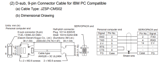
После подключения видим что из алармов последний был A.02: User Constants Breakdown, что означает
Power turned OFF during parameter write. Alarm occurred at next power ON. Питание отключено во время записи параметра. Тревога возникла при следующем включении питания. После инициализации параметров и передергивании питания ошибка исчезла.
- Manuals
- Brands
- YASKAWA Manuals
- Servo Drives
- SGMGH
Manuals and User Guides for YASKAWA SGMGH. We have 5 YASKAWA SGMGH manuals available for free PDF download: User Manual
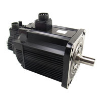
YASKAWA SGMGH User Manual (617 pages)
Servomotors
Brand: YASKAWA
|
Category: Engine
|
Size: 7.73 MB
Table of Contents
-
Safety Information
6
-
Notes for Safe Operation
7
-
Table of Contents
13
-
Outline
25
-
Checking Products
26
-
Check Items
26
-
Servomotors
26
-
-
1 Outline
26
-
Servopacks
27
-
Product Part Names
28
-
Servomotors
28
-
SGMAH and SGMPH Without Gears and Brakes
28
-
SGMGH/SGMSH/SGMDH/SGMUH Without Gears and Brakes
28
-
-
Servopacks
29
-
SGDH for 30 W to 5.0 Kw
29
-
SGDH for 6.0 Kw to 15.0 Kw
30
-
-
-
Examples of Servo System Configurations
31
-
Single-Phase, 100 V, 200 V and 220 V Main Circuit
31
-
Three-Phase, 200 V Main Circuit
32
-
Three-Phase, 400 V Main Circuit
33
-
-
Applicable Standards
34
-
North American Safety Standards (UL, CSA)
34
-
CE Marking
34
-
-
-
2 Selections
35
-
Servomotor Model Designations
36
-
Model SGMAH (3000 Min -1 )
36
-
Without Gears
36
-
With Gears
37
-
-
Model SGMPH (3000 Min -1 )
38
-
Model SGMGH (1500 Min -1 )
40
-
Model SGMGH (1000 Min -1 )
42
-
Model SGMSH (3000 Min -1 )
44
-
Model SGMDH (2000 Min -1 )
46
-
Model SGMUH (6000 Min -1)
47
-
-
Selecting Servomotors
48
-
Support Tool for the Capacity Selection of the AC Servomotors
48
-
Servomotor Capacity Selection Examples
48
-
-
SERVOPACK Model Designations
49
-
Σ-II Series Servopacks and Applicable Servomotors
50
-
Selecting Cables
51
-
Cables for SGMAH and SGMPH Servomotors
51
-
Cables for SGMGH/SGMSH/SGMDH/SGMUH Servomotors
56
-
-
Selecting Peripheral Devices
60
-
Special Options
60
-
Molded-Case Circuit Breaker and Fuse Capacity
63
-
Noise Filters, Magnetic Contactors, Surge Suppressors and DC Reactors
64
-
Regenerative Resistors and Brake Power Supply Units
65
-
Specifications and Dimensional Drawings
67
-
-
-
3 Specifications and Dimensional Drawings
68
-
Ratings and Specifications of SGMAH (3000 Min -1)
70
-
SGMAH Servomotors Without Gears
70
-
SGMAH Servomotors with Standard Backlash Gears
72
-
SGMAH Servomotors with Low-Backlash Gears
74
-
Ratings and Specifications of SGMPH (3000 Min -1)
77
-
SGMPH Servomotors Without Gears
77
-
SGMPH Servomotors with Standard Backlash Gears
79
-
SGMPH Servomotors with Low-Backlash Gears
81
-
Ratings and Specifications of SGMGH (1500 Min -1)
83
-
SGMGH Servomotors (1500Min -1) Without Gears
83
-
3.3.1 SGMGH Servomotors (1500Min
84
-
3.3 Ratings and Specifications of SGMGH (1500Min
85
-
3.3.1 SGMGH Servomotors (1500Min
86
-
3.3 Ratings and Specifications of SGMGH (1500Min
87
-
-
3.3.2 SGMGH Servomotors (1500Min
87
-
SGMGH Servomotors (1500Min -1) with Standard Backlash Gears
87
-
3.3.2 SGMGH Servomotors (1500Min
88
-
3.3 Ratings and Specifications of SGMGH (1500Min
89
-
-
SGMGH Servomotors
89
-
SGMGH Servomotors (1500Min -1) with Low-Backlash Gears
90
-
3.3 Ratings and Specifications of SGMGH (1500Min
91
-
3.4.1 SGMGH Servomotors (1000Min
92
-
Ratings and Specifications of SGMGH (1000Min -1)
92
-
SGMGH Servomotors (1000Min -1) Without Gears
92
-
3.4 Ratings and Specifications of SGMGH (1000Min
93
-
3.4 Ratings and Specifications of SGMGH (1000Min
95
-
SGMGH Servomotors (1000Min -1) with Standard Backlash Gears
95
-
3.4.2 SGMGH Servomotors (1000Min
96
-
3.4.3 SGMGH Servomotors (1000 Min
97
-
SGMGH Servomotors (1000 Min -1) with Low-Backlash Gears
97
-
Ratings and Specifications of SGMSH (3000Min -1)
99
-
SGMSH Servomotors (3000Min -1) Without Gears
99
-
3.5 Ratings and Specifications of SGMSH (3000Min
101
-
3.5 Ratings and Specifications of SGMSH (3000Min
103
-
Ratings and Specifications of SGMDH (2000Min -1)
105
-
SGMDH Servomotors (2000Min -1) with Holding Brakes
105
-
Ratings and Specifications of SGMUH (6000Min -1)
107
-
SGMUH Servomotors (6000Min -1) Without Holding Brakes
107
-
-
Mechanical Specifications of Servomotors
109
-
Precautions on Servomotor Installation
109
-
Mechanical Tolerance
110
-
Direction of Servomotor Rotation
111
-
Impact Resistance
111
-
Vibration Resistance
111
-
Vibration Class
111
-
-
Terms and Data for Servomotors with Gears
112
-
Servomotor Dimensional Drawings
114
-
With Standard Backlash Gears
114
-
With Low-Backlash Gears
114
-
Dimensional Drawings of SGMAH Servomotors (3000 Min -1)
115
-
SGMAH Servomotors (3000 Min -1) Without Gears
115
-
-
-
Without Gears
114
-
Without Gears
116
-
-
Dimensional Drawings of SGMAH Servomotors
117
-
Model SGMAH (3000 Min -1 )
117
-
SGMAH Servomotors (3000 Min -1) with Brakes
119
-
SGMAH Servomotors (3000 Min -1) with Standard Backlash Gears
123
-
SGMAH Servomotors (3000 Min -1) with Standard Backlash Gears and Brakes
130
-
SGMAH Servomotors (3000 Min -1) with Low-Backlash Gears
137
-
Dimensional Drawings of SGMPH Servomotors (3000 Min -1)
145
-
SGMPH Servomotors (3000 Min -1) Without Gears and Brake
145
-
Model SGMPH (3000 Min )
146
-
SGMPH Servomotors (3000 Min -1) with Brakes
147
-
SGMPH Servomotors (3000 Min -1) with Standard Backlash Gears
149
-
SGMPH Servomotors (3000 Min -1) with Standard Backlash Gears and Brakes
152
-
SGMPH Servomotors (3000 Min -1) with Low-Backlash Gears
155
-
Dimensional Drawing of Output Shafts with Oil Seals for SGMAH and SGMPH Servomotors
159
-
-
SGMAH Servomotors
159
-
SGMPH Servomotors
159
-
Dimensional Drawings of SGMGH Servomotors (1500 Min -1)
160
-
SGMGH Servomotors (1500 Min -1) Without Gears and Brakes
160
-
-
Model SGMGH (1500 Min )
164
-
Model SGMGH (1000 Min -1 )
165
-
SGMGH Servomotors (1500Min -1) with Standard Backlash Gears and With-Out Brakes (Foot-Mounted Type)
168
-
SGMGH Servomotors (1500Min -1) with Low-Backlash Gears and Withoutbrakes (Flange-Mounted Type)
182
-
Dimensional Drawings of SGMGH Servomotors (1000 Min -1)
186
-
SGMGH Servomotors (1000 Min -1) Without Gears and Brakes
186
-
SGMGH Servomotors (1000 Min -1) Without Gears and with Brakes
188
-
SGMGH Servomotors (1000 Min -1) with Standard Backlash Gears and With-Out Brakes (Foot-Mounted Type)
191
-
SGMGH Servomotors (1000 Min -1) with Low-Backlash Gears and Withoutbrakes (Flange-Mounted Type)
203
-
Dimensional Drawings of SGMSH Servomotors (3000Min -1)
207
-
SGMSH Servomotors (3000Min -1) Without Gears and Without Brakes
207
-
SGMSH Servomotors (3000 Min -1) 200-V Specifications Without Gears Withbrakes
209
-
SGMSH Servomotors (3000 Min -1) 400-V Specifications Without Gears Withbrakes
211
-
SGMSH Servomotors (3000 Min -1) with Low-Backlash Gears and Withoutbrakes (Flange-Mounted Type)
213
-
Model SGMSH (3000 Min -1 )
216
-
SGMSH Servomotors (3000 Min Without Brakes (Flange-Mounted Type)
216
-
SGMDH Servomotors (2000Min -1) Without Gears and With/Without Brakes
217
-
-
Servomotors SGMGH (1500 Min -1) 400-V Specifications Without Gears and with Brakes
165
-
Dimensional Drawings of SGMDH Servomotors (2000Min -1 )
217
-
With/Without Brakes
217
-
SGMUH Servomotors (6000Min -1) Without Gears and Without Brakes
219
-
-
Dimensional Drawings of SGMUH Servomotors (6000Min -1 )
219
-
Without Gears and Without Brakes
219
-
SGMUH Servomotors (6000Min -1) Without Gears and with Brakes
220
-
-
Shaft End Specifications for SGMGH, SGMSH and SGMDH Servomotors
222
-
-
-
4 SERVOPACK Specifications and Dimensional Drawings
225
-
SERVOPACK Ratings and Specifications
225
-
Single-Phase 100 V
225
-
Three-Phase 400 V
225
-
SERVOPACK Ratings and Specifications
227
-
Single-Phase 100 V
227
-
Single-Phase/Three-Phase 200 V
227
-
Single-Phase 220 V (Option)
228
-
Three-Phase 400 V
228
-
-
SERVOPACK Ratings and Specifications
229
-
-
SERVOPACK Installation
231
-
SERVOPACK Internal Block Diagrams
233
-
Single-Phase 200 V, 30 W to 400 W, and 100 V, 30 W to 200 W Models
233
-
Three-Phase 200 V, 500 W to 1.5 Kw, and Single-Phase 220 V, 800 W, 1.5 Kw Models
234
-
Three-Phase 200 V, 2.0 Kw to 5.0 Kw Models
235
-
Three-Phase 200 V, 6.0 Kw to 15 Kw Models
236
-
Three-Phase 400 V, 500 W to 3.0 Kw Models
237
-
Three-Phase 400 V, 5.0 Kw Model
238
-
Three-Phase 400 V, 6.0 Kw, 7.5 Kw Models
239
-
Three-Phase 400 V, 11.0 Kw, 15.0 Kw Models
240
-
Servopack’s Power Supply Capacities and Power Losses
241
-
SERVOPACK Overload Characteristics and Allowable Load Moment of Inertia
243
-
-
-
Overload Characteristics
243
-
Starting and Stopping Time
244
-
Load Moment of Inertia
244
-
-
SERVOPACK Dimensional Drawings
247
-
Model
247
-
Dimensional Drawings of Base-Mounted SERVOPACK Model
248
-
Single-Phase 100 V: 30 W/50 W/100 W (A3BE/A5BE/01BE)
248
-
Single-Phase 200 V: 30 W/50 W/100 W/200 W (A3AE/A5AE/01AE/02AE)
248
-
-
Single-Phase 100 V: 200 W (02BE) Single-Phase 200 V: 400 W (04AE)
249
-
Three-Phase 200 V: 500 W/750 W/1.0 Kw (05AE/08AE/10AE)
250
-
Single-Phase 220 V: 750 W (08AE-S)
250
-
-
Three-Phase 200 V: 1.5 Kw (15AE)
251
-
Three-Phase 400 V: 500 W/750 W/1.0 Kw/1.5 Kw (05DE/08DE/10DE/15DE)
251
-
Single-Phase 220 V: 1.5 Kw (15AE-S) Three-Phase 200 V: 2.0 Kw/3.0 Kw (20AE/30AE) Three-Phase 400 V: 2.0 Kw/3.0 Kw (20DE/30DE)
252
-
Three-Phase 200 V: 5.0 Kw (50AE) Three-Phase 400 V: 5.0 Kw (50DE)
253
-
Three-Phase 200 V: 6.0 Kw/7.5 Kw (60AE/75AE)
254
-
Three-Phase 400 V: 6.0 Kw/7.5 Kw (60DE/75DE)
255
-
Three-Phase 200 V: 11.0 Kw/15.0 Kw (1AAE/1EAE)
256
-
Three-Phase 400 V: 11.0 Kw/15.0 Kw (1ADE/1EDE)
257
-
Dimensional Drawings of Rack-Mounted SERVOPACK Model
258
-
Single-Phase 100 V: 30 W/50 W/100 W (A3BE-R/A5BE-R/01BE-R)
258
-
Single-Phase 200 V: 30 W/50 W/100 W/200 W (A3AE-R/A5AE-R/01AE-R/02AE-R)
258
-
-
Single-Phase 100 V: 200 W (02BE-R) Single-Phase 200 V: 400 W (04AE-R)
259
-
Single-Phase 220 V: 750 W (08AE-S-R)
260
-
Three-Phase 200 V: 500 W/750 W/1.0 Kw (05AE-R/08AE-R/10AE-R)
260
-
Three-Phase 200 V: 1.5 Kw (15AE-R)
261
-
Three-Phase 400 V: 500 W/750 W/1.0 Kw/1.5 Kw (05DE-R/08DE-R/10DE-R/15DE-R)
261
-
-
Single-Phase 220 V: 1.5 Kw (15AE-S-R)
262
-
Three-Phase 200 V: 2.0 Kw/3.0 Kw (20AE-R/30AE-R)
263
-
Three-Phase 400 V: 2.0 Kw/3.0 Kw (20DE-R/30DE-R)
263
-
-
Three-Phase 200 V: 5.0 Kw (50AE-R) Three-Phase 400 V: 5.0 Kw (50DE-R)
264
-
Dimensional Drawings of Duct-Ventilated SERVOPACK Model
265
-
Three-Phase 200 V: 6.0 Kw/7.5 Kw (60AE-P/75AE-P)
265
-
Three-Phase 400 V: 6.0 Kw/7.5 Kw (60DE-P/75DE-P)
266
-
Three-Phase 200 V: 11.0 Kw/15.0 Kw (1AAE-P/1EAE-P)
267
-
Three-Phase 400 V: 11.0 Kw/15.0 Kw (1ADE-P/1EDE-P)
268
-
-
-
5 Specifications and Dimensional Drawings of Cables and Peripheral Devices
269
-
Main Circuit Cable
269
-
Specifications and Dimensional Drawings of Servomotor Main Circuit Cable
271
-
Cables for SGMAH and SGMPH Servomotors Without Brakes
271
-
Cables for SGMAH and SGMPH Servomotors with Brakes
271
-
Flexible Cables for SGMAH and SGMPH Servomotors Without Brakes
272
-
Flexible Cables for SGMAH and SGMPH Servomotors with Brakes
273
-
Cables for 400 V SGMAH and SGMPH Servomotors Without Brakes
273
-
Cables for 400 V SGMAH and SGMPH Servomotors with Brakes
274
-
Servomotor Main Circuit Wire Size and Connectors
275
-
Wire Size
275
-
SGMAH and SGMPH Servomotor Connectors for Standard Environments
276
-
SGMGH, SGMSH, SGMDH, and SGMUH Servomotor Connector Configurations
279
-
SGMGH Servomotor (1500 Min -1) Connectors for Standard Environments
280
-
-
SGMGH Servomotor
282
-
SGMGH Servomotor (1000 Min -1) Connectors for Standard Environments
283
-
SGMSH Servomotor (3000 Min -1) Connectors for Standard Environments
285
-
SGMDH Servomotor (2000 Min -1) Connectors for Standard Environments
287
-
SGMUH Servomotor (6000 Min -1) Connectors for Standard Environments
287
-
-
Without Brakes
287
-
SGMGH Servomotor (1500 Min -1) Connectors Conforming to IP67 and Euro-Pean Safety Standards
290
-
SGMGH Servomotor (1000 Min -1) Connectors Conforming to IP67 and Euro-Pean Safety Standards
295
-
SGMSH Servomotors (3000 Min -1) Connectors Conforming to IP67 and Euro-Pean Safety Standards
298
-
-
SGMSH Servomotors (3000 Min -1 Without Brakes (Flange-Mounted Type)
298
-
SGMDH Servomotors (2000 Min -1) Connectors Conforming to IP67 and Euro-Pean Safety Standards
302
-
Without Brakes
302
-
With Brakes
302
-
SGMUH Servomotors (6000 Min -1) Connectors Conforming to IP67 and Euro-Pean Safety Standards
303
-
Connector Dimensional Drawings
306
-
-
-
SERVOPACK Main Circuit Wire Size
313
-
Cable Types
313
-
Encoder Cable for SGMGH, SGMSH, SGMDH, and SGMUH Servomotors
316
-
Encoder Cable with Connectors for SGMAH and SGMPH Servomotors
316
-
Encoder Cables for CN2 Connector
316
-
-
Encoder Cable with a SERVOPACK Connector and Encoder Loose Leads for SGMAH and SGMPH Servomotors
317
-
Encoder Cable with a SERVOPACK Connector and Encoder Loose Leads for SGMGH, SGMSH, SGMDH, and SGMUH Servomotors
318
-
Encoder Flexible Cables for SGMAH and SGMPH Servomotors
320
-
Encoder Flexible Cables for SGMGH, SGMSH, SGMDH, and SGMUH Servomotors
321
-
-
Connectors and Cables for Encoder Signals
323
-
Connectors and Cables for SGMAH and SGMPH Servomotors
323
-
Connectors and Cables for SGMGH, SGMSH, SGMDH, and SGMUH Servomotors
325
-
-
Flexible Cables
327
-
I/O Signal Cables for CN1 Connector
328
-
Standard Cables
328
-
Connector Type and Cable Size
328
-
Connection Diagram
330
-
-
Peripheral Devices
331
-
Cables for Connecting Personal Computers
331
-
Digital Operator
332
-
Cables for Analog Monitor
333
-
Connector Terminal Block Converter Unit
334
-
Brake Power Supply Unit
335
-
External Regenerative Resistor
337
-
Regenerative Resistor Unit
339
-
Absolute Encoder Battery
340
-
Molded-Case Circuit Breaker (MCCB)
341
-
Noise Filter
343
-
Magnetic Contactor
348
-
Surge Suppressor
352
-
DC Reactor for Harmonic Suppression
354
-
Variable Resistor for Speed and Torque Setting
356
-
Encoder Signal Converter Unit
357
-
MECHATROLINK-I I/F Unit
358
-
Devicenet I/F Unit
359
-
PROFIBUS-DP I/F Unit
360
-
INDEXER Module
362
-
Setup Support Tool Sigmaindexer
363
-
Fully-Closed I/F Unit
364
-
-
6 Wiring
365
-
Wiring Main Circuit
366
-
Names and Functions of Main Circuit Terminals
366
-
Wiring Main Circuit Power Supply Connector (Spring Type)
368
-
Typical Main Circuit Wiring Examples
369
-
-
Wiring Encoders
372
-
Connecting an Encoder (CN2) and Output Signals from the SERVOPACK (CN1)
372
-
Encoder Connector (CN2) Terminal Layout
373
-
-
Examples of I/O Signal Connections
374
-
Speed Control Mode
374
-
Position Control Mode
375
-
Torque Control Mode
376
-
I/O Signal Connector (CN1) Terminal Layout
377
-
I/O Signal (CN1) Names and Functions
378
-
Interface Circuit
380
-
-
Others
383
-
Wiring Precautions
383
-
Wiring for Noise Control
384
-
Installation Conditions of EMC Directives
387
-
Installation Conditions of UL Standards
390
-
Using more than One SERVOPACK
391
-
Extending Encoder Cables
392
-
Operating Conditions on 400-V Power Supply Voltage
394
-
DC Reactor for Harmonic Suppression
395
-
Regenerative Power and Regenerative Resistance
397
-
Connecting External Regenerative Resistors
397
-
-
-
7 Digital Operator/Panel Operator
402
-
Functions on Digital Operator/Panel Operator
403
-
Connecting the Digital Operator
403
-
Key Names and Functions
404
-
Basic Mode Selection and Operation
405
-
Status Display
407
-
-
Operation in Utility Function Mode (Fn )
409
-
List of Utility Function Modes
409
-
Alarm Traceback Data Display (Fn000)
410
-
Zero-Point Search Mode (Fn003)
411
-
Parameter Settings Initialization (Fn005)
412
-
Alarm Traceback Data Clear (Fn006)
413
-
Automatic Offset-Adjustment of Motor Current Detection Signal
414
-
Manual Offset-Adjustment of Motor Current Detection Signal (Fn00F)
415
-
Password Setting (Protects Parameters from Being Changed) (Fn010)
416
-
Motor Models Display (Fn011)
417
-
Software Version Display (Fn012)
418
-
Application Module Detection Results Clear (Fn014)
419
-
-
Operation in Parameter Setting Mode (Pn )
420
-
Setting Parameters
420
-
Input Circuit Signal Allocation
424
-
Output Circuit Signal Allocation
427
-
-
Operation in Monitor Mode (un )
429
-
List of Monitor Modes
429
-
-
Advertisement
YASKAWA
SGM H Series
User Manual
YASKAWA SGMGH User Manual (615 pages)
Servomotors
Brand: YASKAWA
|
Category: Servo Drives
|
Size: 10.5 MB
Table of Contents
-
Table of Contents
14
-
1 Outline
27
-
Checking Products
27
-
Check Items
27
-
Servomotors
27
-
Servopacks
28
-
-
Product Part Names
29
-
Servomotors
29
-
Servopacks
30
-
-
Examples of Servo System Configurations
32
-
Single-Phase, 100 V and 200 V Main Circuit
32
-
Three-Phase, 200 V Main Circuit
33
-
Connecting to SGMCS Servomotor
34
-
-
Applicable Standards
35
-
North American Safety Standards (UL, CSA)
35
-
CE Marking
35
-
-
Σ-II Series SGDM SERVOPACK Upgraded Functions
36
-
-
2 Selections
38
-
Servomotor Model Designations
39
-
Model SGMAH (3000 Min -1 )
39
-
Model SGMPH (3000 Min -1 )
41
-
Model SGMGH (1500 Min -1 )
43
-
Model SGMGH (1000 Min -1 )
45
-
Model SGMSH (3000 Min -1 )
47
-
Model SGMDH (2000 Min -1 )
49
-
Model SGMCS
50
-
-
Selecting Servomotors
51
-
Support Tool for the Capacity Selection of the AC Servomotors
51
-
Servomotor Capacity Selection Examples
51
-
-
SERVOPACK Model Designations
52
-
Σ-II Series Servopacks and Applicable Servomotors
53
-
SGDM Servopacks and SGM H Servomotors
53
-
SGDM Servopacks and SGMCS Servomotors
54
-
-
Selecting Cables
55
-
Cables for SGMAH and SGMPH Servomotors
55
-
Cables for SGMGH/SGMSH/SGMDH Servomotors
60
-
Cables for SGMCS Servomotors
64
-
-
Selecting Peripheral Devices
67
-
Special Options
67
-
Molded-Case Circuit Breaker and Fuse Capacity
69
-
Noise Filters, Magnetic Conductors, Surge Suppressors and DC Reactors
70
-
Regenerative Resistors and Brake Power Supply Units
71
-
-
-
3 Specifications and Dimensional Drawings
72
-
Ratings and Specifications of SGMAH
75
-
SGMAH Servomotors Without Gears
75
-
SGMAH Servomotors Without Gears
77
-
SGMAH Servomotors with Standard Backlash Gears
78
-
SGMAH Servomotors with Low-Backlash Gears
80
-
SGMAH Servomotors with Low-Backlash Gears
81
-
-
Ratings and Specifications of SGMPH
82
-
SGMPH Servomotors Without Gears
82
-
SGMPH Servomotors with Standard Backlash Gears
84
-
Ratings and Specifications of SGMPH
84
-
SGMPH Servomotors with Low-Backlash Gears
86
-
-
Ratings and Specifications of SGMGH
88
-
SGMGH Servomotors
89
-
Ratings and Specifications of SGMSH
103
-
Ratings and Specifications of SGMDH
108
-
Ratings and Specifications of SGMCS Servomotors
110
-
Small-Capacity Series SGMCS Servomotors
110
-
Middle-Capacity Series SGMCS Servomotors
114
-
-
Mechanical Specifications of SGMAH, SGMPH, SGMGH, SGMSH, and SGMDH Servomotors
116
-
Precautions on Servomotor Installation
116
-
Mechanical Tolerance
117
-
Direction of Servomotor Rotation
118
-
Impact Resistance
118
-
Vibration Resistance
118
-
Vibration Class
118
-
-
Mechanical Specifications of SGMCS Servomotors
119
-
Allowable Loads
119
-
Mechanical Tolerance
120
-
Direction of Servomotor Rotation
121
-
Impact Resistance
121
-
Vibration Resistance
121
-
Vibration Class
121
-
Protective Specification
121
-
-
Terms and Data for Servomotors with Gears
122
-
Servomotor Dimensional Drawings
124
-
SGMAH Servomotors
125
-
Without Gears and with Brakes
128
-
Dimensional Drawings of SGMAH Servomotors
128
-
SGMAH Servomotors
128
-
SGMAH Servomotors
129
-
-
With Standard Backlash Gears
131
-
With Standard Backlash Gears and Brakes
137
-
With Low-Backlash Gears
142
-
Model SGMAH (3000 Min -1 )
145
-
-
Without Gears and Brakes
148
-
Dimensional Drawings of SGMPH Servomotors
148
-
SGMPH Servomotors
148
-
-
With Brakes
150
-
Model SGMPH (3000 Min -1 )
151
-
And Without Brakes
152
-
-
With Standard Backlash Gears and Without Brakes
153
-
With Standard Backlash Gears and Brakes
155
-
With Low-Backlash Gears
159
-
Dimensional Drawing of Output Shafts with Oil Seals for SGMAH and SGMPH Servomotors
163
-
SGMAH Servomotors
163
-
SGMPH Servomotors
163
-
Dimensional Drawings of SGMGH Servomotors
164
-
SGMGH Servomotors (1000 Min (Flange-Mounted Type)
166
-
SGMGH Servomotors
166
-
SGMGH Servomotors
170
-
Dimensional Drawings of SGMGH Servomotors
189
-
SGMGH Servomotors
189
-
SGMGH Servomotors (1000 Min -1 (Flange-Mounted Type)
189
-
SGMGH Servomotors (1000 Min -1 (Flange-Mounted Type)
191
-
-
-
Dimensional Drawings of SGMSH Servomotors
211
-
SGMSH Servomotors
211
-
SGMSH Servomotors (3000 Min (Flange-Mounted Type)
211
-
SGMSH Servomotors (3000 Min -1 (Flange-Mounted Type)
211
-
-
Dimensional Drawings of SGMDH Servomotors
220
-
SGMDH Servomotors
220
-
-
Dimensional Drawings of SGMCS Servomotors
222
-
SGMCS Servomotors Φ135 Model
222
-
SGMCS Servomotors Φ175 Model
222
-
SGMCS Servomotors Φ230 Model
223
-
SGMCS Servomotors Φ290 Model
223
-
SGMCS Servomotors Φ280 Model
224
-
SGMCS Servomotors Φ360 Model
225
-
Servomotor Connector for All Small-Capacity Series Servomotors
226
-
Servomotor Connector for All Middle-Capacity Series Servomotors
227
-
Shaft End Specifications for SGMGH, SGMSH and SGMDH Servomotors
228
-
-
4 SERVOPACK Specifications and Dimensional Drawings
231
-
SERVOPACK Ratings and Specifications
233
-
SERVOPACK Ratings and Specifications
234
-
-
SERVOPACK Installation
236
-
SERVOPACK Internal Block Diagrams
238
-
Single-Phase 200 V, 30 W to 400 W, and 100 V, 30 W to 200 W Models
238
-
Three-Phase 200 V, 500 W to 1.5 Kw Models
239
-
Three-Phase 200 V, 2.0 Kw to 5.0 Kw Models
239
-
Three-Phase 200 V, 6.0 Kw to 15 Kw Models
240
-
-
Servopack’s Power Supply Capacities and Power Losses
241
-
SERVOPACK Overload Characteristics and Allowable Load Moment of Inertia
242
-
Overload Characteristics
242
-
Starting and Stopping Time
243
-
Load Moment of Inertia
243
-
-
SERVOPACK Dimensional Drawings
246
-
Dimensional Drawings of Base-Mounted SERVOPACK Model
247
-
Single-Phase 100 V: 30 W to 100 W (A3BD to 01BD, A3BDA to 01BDA) Single-Phase 200 V: 30 W to 200 W (A3AD to 02AD, A3ADA to 02ADA)
247
-
Single-Phase 100 V: 200 W (02BD, 02BDA) Single-Phase 200 V: 400 W (04AD, 04ADA)
248
-
Three-Phase 200 V: 500 W/750 W/1.0 Kw (05AD to 10AD, 05ADA to 10ADA)
249
-
Three-Phase 200 V: 1.5 Kw (15AD, 15ADA)
250
-
Three-Phase 200 V: 2.0 Kw/3.0 Kw (20AD to 30AD, 20ADA to 30ADA)
251
-
Three-Phase 200 V: 5.0 Kw (50ADA)
252
-
Three-Phase 200 V: 6.0 Kw/7.5 Kw (60ADA to 75ADA)
253
-
Three-Phase 200 V: 11.0 Kw/15.0 Kw (1AADA to 1EADA)
254
-
-
Dimensional Drawings of Rack-Mounted SERVOPACK Model
255
-
Single-Phase 100 V: 30 W/50 W/100 W (A3BD-R to 01BD-R, A3BDA-R to 01BDA-R)
255
-
Single-Phase 200 V: 30 W/50 W/100 W/200 W
255
-
(A3AD-R to 02AD-R, A3ADA-R to 02ADA-R)
255
-
-
Single-Phase 100 V: 200 W (02BD-R, 02BDA-R)
256
-
Single-Phase 200 V: 400 W (04AD-R, 04ADA-R)
256
-
-
Three-Phase 200 V: 500 W/750 W/1.0 Kw (05AD-R to 10AD-R, 05ADA-R to 10ADA-R)
257
-
Three-Phase 200 V: 1.5 Kw (15AD-R, 15ADA-R)
258
-
Three-Phase 200 V: 2.0 Kw/3.0 Kw (20AD-R to 30AD-R, 20ADA-R to 30ADA-R)
259
-
Three-Phase 200 V: 5.0 Kw (50ADA-R)
260
-
-
Dimensional Drawings of Duct-Ventilated SERVOPACK Model
261
-
Three-Phase 200 V: 6.0 Kw/7.5 Kw (60ADA-P to 75ADA-P)
261
-
Three-Phase 200 V: 11.0 Kw/15.0 Kw (1AADA-P/1EADA-P)
262
-
-
-
5 Specifications and Dimensional Drawings of Cables and Peripheral Devices
263
-
Specifications and Dimensional Drawings of Servomotor Main Circuit Cable
265
-
Cables for SGMAH and SGMPH Servomotors Without Brakes
265
-
Cables for SGMAH and SGMPH Servomotors with Brakes
265
-
Flexible Cables for SGMAH and SGMPH Servomotors Without Brakes
266
-
Flexible Cables for SGMAH and SGMPH Servomotors with Brakes
267
-
Cables for SGMCS Servomotors
268
-
-
Servomotor Main Circuit Wire Size and Connectors
270
-
Wire Size
270
-
SGMAH and SGMPH Servomotor Connectors for Standard Environments
271
-
SGMGH, SGMSH, and SGMDH Servomotor Connector Configurations
274
-
SGMGH Servomotor
275
-
SGMSH Servomotor
279
-
SGMDH Servomotor
280
-
Without Gears and With/Without Brakes
280
-
SGMGH Servomotor
281
-
European Safety Standards
281
-
-
SGMGH Servomotor
284
-
European Safety Standards
284
-
-
SGMSH Servomotors
287
-
European Safety Standards
287
-
-
SGMDH Servomotors
290
-
European Safety Standards
290
-
-
Connectors for SGMCS Servomotors
291
-
Connector Dimensional Drawings
293
-
-
SERVOPACK Main Circuit Wire Size
300
-
Encoder Cables for CN2 Connector
302
-
Encoder Cable with Connectors for SGMAH and SGMPH Servomotors
302
-
Encoder Cable with Connectors for SGMGH, SGMSH, and SGMDH Servomotors
302
-
Encoder Cable with a SERVOPACK Connector and Encoder Loose Leads for SGMAH and SGMPH Servomotors
303
-
Encoder Cable with a SERVOPACK Connector and Encoder Loose Leads for SGMGH, SGMSH, and SGMDH Servomotors
304
-
Encoder Flexible Cables for SGMAH and SGMPH Servomotors
306
-
-
Connectors and Cables for Encoder Signals
310
-
Connectors and Cables for SGMAH and SGMPH Servomotors
310
-
Connectors and Cables for SGMGH, SGMSH, and SGMDH Servomotors
312
-
Connectors and Cables for SGMCS Servomotors
314
-
-
Flexible Cables
315
-
I/O Signal Cables for CN1 Connector
316
-
Standard Cables
316
-
Connector Type and Cable Size
316
-
Connection Diagram
318
-
-
Peripheral Devices
319
-
Cables for Connecting Personal Computers
319
-
Digital Operator
320
-
Cables for Analog Monitor
321
-
Connector Terminal Block Converter Unit
322
-
Brake Power Supply Unit
323
-
External Regenerative Resistor
325
-
Regenerative Resistor Unit
327
-
Absolute Encoder Battery
328
-
Molded-Case Circuit Breaker (MCCB)
330
-
Noise Filter
331
-
Magnetic Contactor
336
-
Surge Suppressor
338
-
DC Reactor for Harmonic Suppression
340
-
Variable Resistor for Speed and Torque Setting
342
-
Encoder Signal Converter Unit
343
-
-
-
6 Wiring
344
-
Wiring Main Circuit
345
-
Names and Functions of Main Circuit Terminals
345
-
Wiring Main Circuit Power Supply Connector (Spring Type)
347
-
Typical Main Circuit Wiring Examples
348
-
-
Wiring Encoders
350
-
Connecting an Encoder (CN2) and Output Signals from the SERVOPACK (CN1)
350
-
Encoder Connector (CN2) Terminal Layout
351
-
-
Examples of I/O Signal Connections
352
-
Speed Control Mode
352
-
Position Control Mode
353
-
Torque Control Mode
354
-
I/O Signal Connector (CN1) Terminal Layout
355
-
I/O Signal (CN1) Names and Functions
356
-
Interface Circuit
358
-
-
Others
361
-
Wiring Precautions
361
-
Wiring for Noise Control
362
-
Installation Conditions of EMC Directives
365
-
Installation Conditions of UL Standards
367
-
Using more than One SERVOPACK
368
-
Extending Encoder Cables
369
-
Operating Conditions on 400-V Power Supply Voltage
371
-
DC Reactor for Harmonic Suppression
372
-
-
Connecting Regenerative Resistors
374
-
Regenerative Power and Regenerative Resistance
374
-
Connecting External Regenerative Resistors
374
-
-
-
7 Digital Operator/Panel Operator
379
-
Functions on Digital Operator/Panel Operator
380
-
Connecting the Digital Operator
380
-
Key Names and Functions
381
-
Basic Mode Selection and Operation
382
-
Status Display
384
-
-
Operation in Utility Function Mode (Fn )
386
-
List of Utility Function Modes
386
-
Alarm Traceback Data Display (Fn000)
387
-
Zero-Point Search Mode (Fn003)
388
-
Parameter Settings Initialization (Fn005)
389
-
Alarm Traceback Data Clear (Fn006)
390
-
Automatic Offset-Adjustment of Motor Current Detection Signal (Fn00E)
391
-
Manual Offset-Adjustment of Motor Current Detection Signal (Fn00F)
392
-
Password Setting (Protects Parameters from Being Changed) (Fn010)
393
-
Motor Models Display (Fn011)
394
-
Software Version Display (Fn012)
395
-
-
Operation in Parameter Setting Mode (Pn )
396
-
Setting Parameters
396
-
Input Circuit Signal Allocation
400
-
Output Circuit Signal Allocation
403
-
-
Operation in Monitor Mode (un )
405
-
List of Monitor Modes
405
-
-
YASKAWA SGMGH User Manual (488 pages)
Sigma II Series Servo System
Brand: YASKAWA
|
Category: Servo Drives
|
Size: 6.7 MB
Table of Contents
-
Notes
11
-
Table of Contents
11
-
-
Checking Product and Part Names
19
-
Chapter 1 : Checking Product and Part Names
20
-
Checking the Sigma II Series Products on Delivery
20
-
Servomotors
20
-
Direct-Drive Motor Supporting Function
22
-
Servo Amplifiers
24
-
-
Product Part Names
26
-
Servomotors
26
-
Servo Amplifiers
27
-
-
-
-
2 Installation
29
-
Chapter 2 : Installation
30
-
Installation Site
30
-
Storage Temperature
30
-
Alignment
31
-
Orientation
31
-
Allowable Shaft Loads
32
-
Vibration Resistance
33
-
Cable Stress
34
-
Handling Oil and Water
34
-
Vibration Class
34
-
Servo Amplifiers
35
-
Installation Site
35
-
Storage Conditions
35
-
Orientation
36
-
Installation
37
-
-
-
Servomotors
30
-
-
3 Wiring
39
-
Connecting to Peripheral Devices
41
-
Chapter 3 : Wiring
42
-
Single-Phase (100V or 200V) Main Circuit Specifications
42
-
Three-Phase (200V) Main Circuit Specifications
43
-
Three-Phase (400V) Main Circuit Specifications
44
-
Servo Amplifier Internal Block Diagrams
45
-
To 400W (200V) and 30W to 200W (100V) Models
45
-
Kw to 1.5Kw (200V) Models
46
-
Kw to 5.0Kw (200V) Models
46
-
Kw to 15.0Kw (200V) Models
47
-
Kw to 3.0Kw, 400V Models
47
-
Kw (400V) Models
48
-
Kw to 7.5Kw, 400V Models
48
-
Kw to 15.0Kw (400V) Models
49
-
Kw to 55Kw (400V) Models
49
-
-
Main Circuit Wiring
50
-
Names and Descriptions of Main Circuit Terminal
51
-
Cable Specifications and Peripheral Devices
52
-
Typical Main Circuit Wiring Example
52
-
Servo Amplifier Power Losses
53
-
Wiring Main Circuit Terminal Blocks
54
-
-
I/O Signals
55
-
Example of Typical I/O Signal Connections
55
-
List of CN1 Terminals
56
-
I/O Signal Names and Functions
57
-
Interface Circuits
59
-
-
Wiring Encoders (for SGMGH and SGMSH Motors Only)
62
-
Encoder Connections
62
-
CN2 Encoder Connector Terminal Layout and Types
64
-
-
Examples of Standard Connections
65
-
Single-Phase Power Supply Specifications
65
-
Three-Phase Power Supply Specifications (200V)
66
-
Three-Phase Power Supply Specifications (400V)
67
-
Position Control Mode
70
-
Speed Control Mode
71
-
Torque Control Mode
72
-
-
-
-
4 Trial Operation
73
-
Two-Step Trial Operation
74
-
Chapter 4 : Trial Operation
75
-
Step 1: Trial Operation for Servomotor Without Load
75
-
Step 2: Trial Operation with the Servomotor Connected to a Load
81
-
Additional Setup Procedures in Trial Operation
82
-
Servomotors with Brakes
82
-
Position Control by Host Controller
83
-
-
Minimum Parameters and Input Signals
84
-
Input Signals
84
-
Parameters
84
-
-
-
-
Parameter Settings and Functions
85
-
Parameters
88
-
Chapter 5 : Parameter Settings and Functions
89
-
Switching Servomotor Rotation Direction
89
-
Setting the Overtravel Limit Function
90
-
Limiting Torque
93
-
Settings According to Host Controller
98
-
Speed Reference
98
-
Position Reference
100
-
Using the Encoder Signal Output
106
-
Sequence I/O Signals
110
-
Using the Electronic Gear Function
112
-
Contact Input Speed Control
116
-
Using Torque Control
121
-
Torque Feed-Forward Function
128
-
Speed Feed-Forward Function
129
-
Torque Limiting by Analog Voltage Reference
131
-
Reference Pulse Inhibit Function (/INHIBIT)
133
-
-
Setting up the Servo Amplifier
135
-
Parameters
135
-
JOG Speed
136
-
Input Circuit Signal Allocation
137
-
Output Circuit Signal Allocation
141
-
Control Mode Selection
143
-
-
Setting Stop Functions
146
-
Adjusting Offset
146
-
Servo off Stop Mode Selection
147
-
Using the Zero Clamp Function
148
-
Using the Holding Brake
150
-
-
Forming a Protective Sequence
154
-
Using Servo Alarm and Alarm Code Outputs
154
-
Using the Servo on Input Signal (/S-ON)
156
-
Using the Positioning Completed Output Signal (/COIN)
157
-
Speed Coincidence Output (/V-CMP)
159
-
Using the Running Output Signal (/TGON)
160
-
Using the Servo Ready Output Signal (/S-RDY)
162
-
Using the Warning Output Signal (/WARN)
163
-
Using the Near Output Signal (/NEAR)
165
-
Handling Power Loss
166
-
-
Selecting a Regenerative Resistor
167
-
External Regenerative Resistor
168
-
Calculating the Regenerative Power Capacity
170
-
-
Absolute Encoders
180
-
Interface Circuit
181
-
Configuring an Absolute Encoder
182
-
Handling Batteries
183
-
Absolute Encoder Setup
184
-
Absolute Encoder Reception Sequence
188
-
-
Special Wiring
193
-
Wiring Precautions
193
-
Wiring for Noise Control
200
-
Using more than One Servodrive
204
-
Extending Encoder Cables
205
-
Power Supply Voltage
207
-
Reactor for Harmonic Suppression
209
-
DB Unit
211
-
-
Reserved Parameters
213
-
List of Upgraded Functions
214
-
Additional Functions
214
-
Improved Functions
214
-
Or Higher.)
214
-
Improvement of Dividing Output Resolution
216
-
Reference Pulse Input Multiplication Range Switching Function
220
-
-
Improved Functions
223
-
Adaptation to Single-Turn Data Absolute Encoder
223
-
Moment of Inertia Ratio Setting Range
223
-
Improvement of Linear Motor Related Specifications
225
-
Supporting Function for Linear Motor with Hall Sensor
227
-
-
-
Settings According to Device Characteristics
89
-
-
Servo Adjustment
229
-
Chapter 6 : Servo Adjustment
230
-
Using the Soft Start Function
230
-
Smoothing
231
-
Adjusting Gain
232
-
Adjusting Offset
233
-
Setting the Torque Reference Filter Time Constant
233
-
Notch Filter
234
-
High-Speed Positioning
238
-
Setting Servo Gain
238
-
Using Feed-Forward Control
240
-
Using Proportional Control
241
-
Setting Speed Bias
242
-
Using Mode Switch
243
-
Automatic Gain Switching Function
247
-
Or Higher)
247
-
Speed Feedback Compensation
250
-
-
Auto-Tuning
252
-
Online Auto-Tuning
253
-
Mechanical Rigidity Settings for Online Auto-Tuning
255
-
Saving Results of Online Auto-Tuning
257
-
Parameters Related to Online Auto-Tuning
259
-
-
Servo Gain Adjustments
261
-
Basic Rules of Gain Adjustment
261
-
Servo Gain Parameters
261
-
Making Manual Adjustments
263
-
Gain Setting Reference Values
268
-
-
Analog Monitor
270
-
-
Smooth Operation
230
-
-
Using the Digital Operator
271
-
Basic Operation
272
-
Chapter 7 : Using the Digital Operator
272
-
Connecting the Digital Operator
272
-
Functions
273
-
Resetting Servo Alarms
274
-
Basic Mode Selection
275
-
Status Display Mode
275
-
Operation in Parameter Setting Mode
278
-
Operation in Monitor Mode
284
-
Applied Operation
290
-
Operation in Alarm Traceback Mode
291
-
JOG Operation Using the Digital Operator
292
-
Automatic Adjustment of the Speed and Torque Reference Offset
295
-
Manual Adjustment of the Speed and Torque Reference Offset
297
-
Clearing Alarm Traceback Data
303
-
Checking the Motor Model
304
-
Checking the Software Version
308
-
Origin Search Model
309
-
Initializing Parameter Settings
312
-
Analog Monitor Output
314
-
Manual Zero Adjustment and Gain Adjustment of Analog Monitor Output7-44
314
-
Adjusting the Motor Current Detection Offset
319
-
Write Protected Setting
323
-
Clearing the Option Unit Detection Alarm
324
-
-
-
Advertisement
YASKAWA SGMGH User Manual (578 pages)
AC Servo Drives
Brand: YASKAWA
|
Category: Servo Drives
|
Size: 15.75 MB
Table of Contents
-
Table of Contents
13
-
1 Outline
24
-
Checking Products
25
-
Check Items
25
-
Servomotors
25
-
Servopacks
26
-
-
Product Part Names
27
-
Servomotors
27
-
Servopacks
29
-
-
Examples of Servo System Configurations
31
-
Single-Phase, 100 V and 200 V Main Circuit
31
-
Three-Phase, 200 V Main Circuit
32
-
Connecting to SGMCS Servomotor
33
-
-
Applicable Standards
34
-
North American Safety Standards (UL, CSA)
34
-
CE Marking
34
-
-
Σ-II Series SGDM SERVOPACK Upgraded Functions
35
-
-
2 Selections
37
-
Servomotor Model Designations
38
-
Model SGMAH (3000 Min -1 )
38
-
Model SGMPH (3000 Min -1 )
40
-
Model SGMGH (1500 Min -1 )
44
-
Model SGMGH (1000 Min -1 )
44
-
Model SGMGH (1000 Min )
44
-
Model SGMSH (3000 Min -1 )
46
-
Model SGMDH (2000 Min -1 )
48
-
Model SGMCS
49
-
-
SERVOPACK Model Designations
50
-
Σ-II Series Servopacks and Applicable Servomotors
51
-
SGDM Servopacks and SGM H Servomotors
51
-
SGDM Servopacks and SGMCS Servomotors
52
-
-
Selecting Cables
53
-
Cables for SGMAH and SGMPH Servomotors
53
-
Cables for SGMGH/SGMSH/SGMDH Servomotors
56
-
Cables for SGMCS Servomotors
59
-
-
Selecting Peripheral Devices
62
-
Special Options
62
-
Molded-Case Circuit Breaker and Fuse Capacity
64
-
Noise Filters, Magnetic Conductors, Surge Absorbers and DC Reactors
65
-
Regenerative Resistors and Brake Power Supply Units
66
-
-
3 Servomotor Specifications and Dimensional Drawings
68
-
Ratings and Specifications of SGMAH
70
-
SGMAH Servomotors Without Gears
70
-
Ratings and Specifications of SGMAH
71
-
SGMAH Servomotors with Standard Backlash Gears
72
-
SGMAH Servomotors with Low-Backlash Gears
74
-
-
Ratings and Specifications of SGMPH
76
-
SGMPH Servomotors Without Gears
76
-
SGMPH Servomotors with Standard Backlash Gears
79
-
SGMPH Servomotors with Low-Backlash Gears
80
-
-
Ratings and Specifications of SGMGH
81
-
Ratings and Specifications of SGMGH
83
-
-
Ratings and Specifications of SGMSH
93
-
Ratings and Specifications of SGMDH
97
-
SGMDH Servomotors
97
-
-
Ratings and Specifications of SGMCS Servomotors
99
-
Small-Capacity Series SGMCS Servomotors
99
-
Middle-Capacity Series SGMCS Servomotors
102
-
-
Mechanical Specifications of SGMAH, SGMPH, SGMGH, SGMSH, and SGMDH Servomotors
104
-
Servomotors
104
-
Precautions on Servomotor Installation
104
-
Mechanical Tolerance
105
-
Direction of Servomotor Rotation
105
-
Impact Resistance
106
-
Vibration Resistance
106
-
Allowable Loads
107
-
Mechanical Specifications of SGMCS Servomotors
107
-
Direction of Servomotor Rotation
108
-
Mechanical Tolerance
108
-
Enclosure
109
-
Heating Conditions
109
-
Impact Resistance
109
-
Vibration Class
109
-
Vibration Resistance
109
-
-
Terms and Data for Servomotors with Gears
110
-
Servomotor Dimensional Drawings
112
-
Dimensional Drawings of SGMAH Servomotors
113
-
Dimensional Drawings of SGMPH Servomotors
132
-
SGMPH Servomotors
132
-
And Without Brakes
136
-
-
Dimensional Drawing of Output Shafts with Oil Seals for SGMAH and SGMPH Servomotors
145
-
SGMAH Servomotors
145
-
SGMPH Servomotors
145
-
Dimensional Drawings of SGMGH Servomotors
146
-
Servomotors
146
-
With Brakes
148
-
SGMGH Servomotors
155
-
SGMGH Servomotors
161
-
SGMGH Servomotors (1500 Min Brakes (Flange-Mounted Type)
161
-
Dimensional Drawings of SGMGH Servomotors
164
-
With Standard Backlash Gears and
169
-
With Standard Backlash Gears and
174
-
With Low-Backlash Gears and Without
179
-
Dimensional Drawings of SGMDH Servomotors
190
-
SGMCS Servomotors Φ135 Model
192
-
SGMCS Servomotors Φ175 Model
193
-
SGMCS Servomotors Φ230 Model
194
-
SGMCS Servomotors Φ290 Model
195
-
SGMCS Servomotors Φ280 Model
196
-
SGMCS Servomotors Φ360 Model
197
-
Shaft End Specifications for SGMGH, SGMSH and SGMDH Servomotors
201
-
SGMSH Servomotors
203
-
SGMDH Servomotors
204
-
-
-
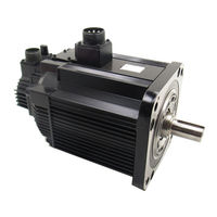
YASKAWA SGMGH User Manual (408 pages)
Brand: YASKAWA
|
Category: Engine
|
Size: 6.88 MB
Table of Contents
-
Table of Contents
377
-
Connecting the GL-Series MC20 Motion Module
378
-
Connecting the CP-9200SH Servo Controller Module (SVA)
379
-
Connecting the GL-Series B2813 Positioning Module
380
-
Connecting Omron’s C500-NC221 Position Control Unit
381
-
Connecting Omron’s C500-NC112 Position Control Unit
382
-
Connecting Mitsubishi’s AD72 Positioning Unit
383
-
Connecting Mitsubishi’s AD75 Positioning Unit
384
Advertisement
Related Products
-
YASKAWA SGMGV
-
YASKAWA SGMGV series
-
YASKAWA SGMAH
-
YASKAWA SGM7D-03H
-
YASKAWA SGM-A5
-
YASKAWA SGM-08
-
YASKAWA SGMCV
-
YASKAWA SGM7A
-
YASKAWA SGM-A3A
-
YASKAWA SGM-08A
YASKAWA Categories
Controller
DC Drives
Servo Drives
Robotics
Control Unit
More YASKAWA Manuals