
-
Contents
-
Table of Contents
-
Bookmarks
Quick Links
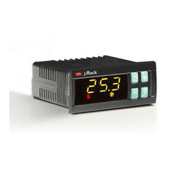
µRack
Standard compressor racks single/two circuit
User manual
NO POWER
& SIGNAL
CABLES
TOGETHER
READ CAREFULLY IN THE TEXT!
Related Manuals for Carel MRK0000000
Summary of Contents for Carel MRK0000000
-
Page 1
µRack Standard compressor racks single/two circuit User manual NO POWER & SIGNAL CABLES TOGETHER READ CAREFULLY IN THE TEXT! -
Page 3
Each CAREL product, in relation to its advanced level of technology, requires setup / configuration / programming / commissioning to be able to operate in the best possible way for the specific application. The failure to complete such operations, which are required/indicated in the user manual, may cause the final product to malfunction; CAREL accepts no liability in such cases. -
Page 5: Table Of Contents
CONTENTS PRODUCT ………………………………….7 General functions ………………………………..7 Main characteristics ………………………………..7 USER INTERFACE ………………………………..8 Buttons — LEDs — Icons ………………………………..8 LED display and Icons ………………………………..9 STARTING THE UNIT ………………………………10 Starting for the first time ………………………………10 Unit configuration ………………………………..10 Meaning of the inputs / outputs …………………………….10 COMPRESSOR MANAGEMENT …………………………….
-
Page 6
APPENDIX: CHANGES INTRODUCED IN FW RELEASE 2.0 FOR MRK0000XX0 …………….41 APPENDIX: CHANGES INTRODUCED IN FW RELEASE 2.1 ………………….42 APPENDICE: MODIFICHE INTRODOTTE NELLA RELEASE FW 2.2 ………………..42… -
Page 7: Product
(only from MANUFACTURER R level). Hardw ware • The product co omes ready for pa anel installation, 3 2×74, and DIN rai il mounting. Cod. C CAREL +03P220 0431 rel. 2.2 date d 10/02/12…
-
Page 8: User Interface
/fan set point high/lo ow threshold to switch the displ lay of the same pa arameter from BA AR to °C. Tab. 2.a Cod. C CAREL +03P220 0431 rel. 2.2 date d 10/02/12…
-
Page 9: Led Display And Icons
2) If flashing indicates the ON/OFF call for a new compressor step, while the device is awaiting the expiry of the delay times. 3) If the controller is used for fan control only (“/01”=0) then the icon shows the status of the fans. Tab. 2.b Cod. CAREL +03P220431 rel. 2.2 dated 10/02/12…
-
Page 10: Starting The Unit
RIC pressure probe e (0 to 5 Volt) or NTC if /16 Room tem perature probe (d display) / auxiliary y probe CAREL NTC temperature prob be (-50T100°C; R/ /T 10 k at 25°C) Outside air r temperature pro obe (floating cond…
-
Page 11
Power contactor for starting the fan / voltage-free contact for signalling unit alarm Tab. 3.c Analogue outputs Outputs Description Fans speed controller (PWM) Tab. 3.d 3.3.2 Wiring diagrams: Panel installation: Line PSOPZKEY* 24 V MCH2004850 Line TRADR1W04 Fig. 3.a Cod. CAREL +03P220431 rel. 2.2 dated 10/02/12… -
Page 12
µRack DIN rail installation: Rack FCSER00000 Line Rack FCSER00000 24 V Line TRADR1W04 Fig. 3.b Cod. CAREL +03P220431 rel. 2.2 dated 10/02/12… -
Page 13: Compressor Management
In this cas se too, the first de evice stops immed diately, while the o others wait the de elay time between n stops (r09). Cod. C CAREL +03P220 0431 rel. 2.2 date d 10/02/12…
-
Page 14: Number Of Compressors Started With Probe 1 Fault
For two circuits, the parameter relating to the second circuit /08 must also be set. This will be related to the probe in the 2nd circuit. Cod. CAREL +03P220431 rel. 2.2 dated 10/02/12…
-
Page 15: Compressors With Different Capacities
On unit models with capacity control (/01=9,10,…14) the compressors cannot be manually enabled/disabled directly. To exploit parameters M01,..,M08, the unit model needs to be changed (/01=1 for configurations 9, 10 and 11; /01=3 for configurations 12 and 13; /01=4 for configuration 14). Cod. CAREL +03P220431 rel. 2.2 dated 10/02/12…
-
Page 16: Special Mt-Lt Units
(par rameter C01). Comp ressor call T[s] Comp ressor MinOn Minim mum ON time Time T[s] TMinOn Fig 4.f Cod. C CAREL +03P220 0431 rel. 2.2 date d 10/02/12…
-
Page 17
This parameter limits the number of starts per hour. If, for example, the maximum allowable number of starts per hour is 10, to guarantee this limit simply set a value of 360 (parameter C05). Key: Compressor call T[s] Compressor TSameSw Minimum time between starts of the same compressor Time T[s] TSameSw Fig 4.i Cod. CAREL +03P220431 rel. 2.2 dated 10/02/12… -
Page 18: Fan And Inverter Management
-calculated base d from actual num mber of fans a vailable. Two d ifferent types of r rotation can be s Cod. C CAREL +03P220 0431 rel. 2.2 date d 10/02/12…
-
Page 19: Inverter Management
Discharge set point + Fan differential Min In Minimum value of the inverter control output Fig.5.d Proportional control, set by parameter r21, may be proportional only (parameter r21=0) or proportional + integral (parameter r21=1). Cod. CAREL +03P220431 rel. 2.2 dated 10/02/12…
-
Page 20
Key: InPress Discharge pressure Set point + differential StpM HP set point DOnZ Activation zone DOffZ Deactivation zone Dead band T [s] Time Inverter Inverter status NFan Number of fans on Fig. 5.f Cod. CAREL +03P220431 rel. 2.2 dated 10/02/12… -
Page 21: Pwm-Ppm Management
T[s] Fig. 5.g The PWM signal controls, for example, the CAREL FCS* series, CONVONOFF, CON0/10A0 modules. ON/OFF fan control board (code CONVONOFF0) The CONVONOFF0 modules convert the PWM signal sent from terminal Y to an ON/OFF signal. In practical terms, Y can be used to control a relay. Switching power 10A at 250 Vac in AC1 (1/3 HP inductive).
-
Page 22: Various Settings
). This alarm has a automatic reset, w with a fixed differe ential of 2°C. Examp ple of HT alarm m management Diff. 2°C Alarm ON temperature Set Poi Alarm OF Fig. 6.a Cod. C CAREL +03P220 0431 rel. 2.2 date d 10/02/12…
-
Page 23: Prevent High Discharge Pressure
Prevent HP activation threshold Time between compressor stops with prevent HP active Dprev1 Step activation delay after end prevent HP (prevent time 1) Dprev2 Minimum time for activation of high prevent frequency alarm (prevent time 2) Cod. CAREL +03P220431 rel. 2.2 dated 10/02/12…
-
Page 24: Alarm Management
OFF CIRC 2 automatic (from multifunctio on input) General discharge e pressure switch All com mps. OFF Settable (from multifunctio on input) Low discharge pre essure All fa ans OFF automatic settable Cod. C CAREL +03P220 0431 rel. 2.2 date d 10/02/12…
-
Page 25: Alarms From Analogue Inputs: Temperature Probe And Pressure Transducer
1.0 bar discharge Example of LP alarm management Diff. Alarm on Alarm off Low press. Set Point Fig. 7.a Diff. Example of HP alarm management Alarm on High press. Set Point Alarm off Fig. 7.b Cod. CAREL +03P220431 rel. 2.2 dated 10/02/12…
-
Page 26: The Supervisor Network
1. For fur rther information, refer to the corre esponding manua l or contact CAREL User interf face The pa arameters are divi ded into 2 catego ories. Display…
-
Page 27: List Of Parameters
Config uration menu Set the typ e of unit, LT, MT or two circuit 0) LT Type o f unit 0 to 2 1) MT 2) TWO CI RCUIT Cod. C CAREL +03P220 0431 rel. 2.2 date d 10/02/12…
-
Page 28
0) probe not connected B1 probe type 0 to 2 1) NTC probe 2) 0 to 5 V probe MIN suction pressure Set the minimum value of suction probe -1.0 to /19 -1.0 Cod. CAREL +03P220431 rel. 2.2 dated 10/02/12… -
Page 29
Used to change the password to access the Manufacturer branch 0 to 999 B4 probe set: 0) probe not connected B4 probe type 0 to 2 1)0 to 5 V probe 2) 0 to 5 V probe Cod. CAREL +03P220431 rel. 2.2 dated 10/02/12… -
Page 30
0 to 20.0 Fan differential Fan differential For single circuit only °C 0 to 20.0 15.5 Only if the inverter is Inverter set point Fan inverter set point r25 to r26 °C 35.7 enabled Cod. CAREL +03P220431 rel. 2.2 dated 10/02/12… -
Page 31
On the 3rd activation, within the set time, the low pressure alarm from 0 to 999 alarms pressure switch changes from automatic to manual reset. Enable unit OFF due to probe disconnected/alarm OFF due to probe 0) NO disconnected 1) YES Maintenance menu Cod. CAREL +03P220431 rel. 2.2 dated 10/02/12… -
Page 32: On/Off Fan Control Board (Code Convonoff0)
O ON/OFF control of the condenser fa ans. The co ontrol relay has a s switching power 1 10A at 250 Vac in AC1 (1/3 HP indu uctive). Fig. 11.a Cod. C CAREL +03P220 0431 rel. 2.2 date d 10/02/12…
-
Page 33: Pwm To 0 To 10 Vdc (Or 4 To 20 Ma) Conversion Board For Fans (Code Conv0/10A0)
To assist t the identification o of the key to be u sed, CAREL has a pplied a label that t can used to desc cribe the program mming made or th he unit that the da ta refers to.
-
Page 34
Reset compressor 1 hours Reset compressor 2 hours Reset compressor 3 hours Reset compressor 4 hours Enable floating condenser control Enable unit Off due to probe fault Enable fans with compressor ON Tab. 14.b Cod. CAREL +03P220431 rel. 2.2 dated 10/02/12… -
Page 35
Version of the application Type of refrigerant Capacity of compressor 1 Capacity of compressor 2 Capacity of compressor 3 Capacity of compressor 4 Inverter readout % “ Multifunction DI configuration B1 type probe Cod. CAREL +03P220431 rel. 2.2 dated 10/02/12… -
Page 36: Default Configurations
3 Fan 1 Normally y open contact, re elay no. 4 Fan 2 Normally y open contact, re elay no. 5 Generic a alarm b. 15.d Cod. C CAREL +03P220 0431 rel. 2.2 date d 10/02/12…
-
Page 37: Glossary
Buffer (memory): memory y on the board used d to save the default t values selected by CAREL for all the pa arameters. Permane nt memory, saves th he values even whe n power is disconne ected.
-
Page 38: Product Codes List
-1…9,3 bar -1…12,8 bar 0…34,5 bar probe MRK0 00010DK MRK0 000200K panel panel MRK0 00030DK MRK0 000400K panel panel MRK0 00050DK MRK0 000600K panel panel MRK0 00090DK MRK0 000800K panel panel Cod. C CAREL +03P220 0431 rel. 2.2 date d 10/02/12…
-
Page 39: Appendix: Compressor Rack Controller, Examples Of Application Diagrams
C4 C3 C2 2 C1 Fig. 17.a 2 com mpressors un it + 2 conden ser fans F2 F1 C2 2 C1 Fig. 17.b Cod. C CAREL +03P220 0431 rel. 2.2 date d 10/02/12…
-
Page 40
3 compressors unit with 2 fan steps and speed regulator (no alarm relay output) F1 C3 C2 C1 Fig. 17.c 2 compressors unit + 3 condenser fans F2 F1 C2 C1 Fig. 17.d Cod. CAREL +03P220431 rel. 2.2 dated 10/02/12… -
Page 41
The default val lue has been chan nged from 90 sec to 60 min The max. value e has been change ed from 999 sec t to 500 min Cod. C CAREL +03P220 0431 rel. 2.2 date d 10/02/12… -
Page 42
/01= 9,10,11,12,13 an d 14” CARE EL reserves the ri ght to make mod difications or chan nges to its produc cts without prior notice. Cod. C CAREL +03P220 0431 rel. 2.2 date d 10/02/12… -
Page 44
CAREL INDUSTRIES HQs Via dell’Industria, 11 — 35020 Brugine — Padova (Italy) Tel. (+39) 049.9716611 Fax (+39) 049.9716600 http: //www.carel.com e-mail: carel@carel.com…
инструкцияCarel µRack

µRack
µRack
Стандартные электронные блоки управления компрессорными
станциями с одним/двумя контурами
Руководство по эксплуатации
NO POWER
& SIGNAL
CABLES
TOGETHER
READ CAREFUL LY IN THE TEXT!
Посмотреть инструкция для Carel µRack бесплатно. Руководство относится к категории без категории, 1 человек(а) дали ему среднюю оценку 8.3. Руководство доступно на следующих языках: русский. У вас есть вопрос о Carel µRack или вам нужна помощь? Задайте свой вопрос здесь
Нужна помощь?
У вас есть вопрос о Carel а ответа нет в руководстве? Задайте свой вопрос здесь Дай исчерпывающее описание проблемы и четко задайте свой вопрос. Чем детальнее описание проблемы или вопроса, тем легче будет другим пользователям Carel предоставить вам исчерпывающий ответ.
Количество вопросов: 0


Главная
Не можете найти ответ на свой вопрос в руководстве? Вы можете найти ответ на свой вопрос ниже, в разделе часто задаваемых вопросов о Carel µRack.
Инструкция Carel µRack доступно в русский?
Не нашли свой вопрос? Задайте свой вопрос здесь
WARNINGS
CAREL bases the development of its products on decades of experience in HVAC, on the continuous investments in technological innovations to products, procedures and strict quality
processes with in-circuit and functional testing on 100% of its products, and on the most innovative production technology available on the market. CAREL and its subsidiaries nonetheless
cannot guarantee that all the aspects of the product and the software included with the product respond to the requirements of the final application, despite the product being developed
according to start-of-the-art techniques. The customer (manufacturer, developer or installer of the final equipment) accepts all liability and risk relating to the configuration of the product in
order to reach the expected results in relation to the specific final installation and/or equipment. CAREL may, based on specific agreements, acts as a consultant for the positive
commissioning of the final unit/application, however in no case does it accept liability for the correct operation of the final equipment/system.
The CAREL product is a state-of-the-art product, whose operation is specified in the technical documentation supplied with the product or can be downloaded, even prior to purchase, from
the website www.carel.com.
Each CAREL product, in relation to its advanced level of technology, requires setup / configuration / programming / commissioning to be able to operate in the best possible way for the
specific application. The failure to complete such operations, which are required/indicated in the user manual, may cause the final product to malfunction; CAREL accepts no liability in such
cases.
Only qualified personnel may install or carry out technical service on the product.
The customer must only use the product in the manner described in the documentation relating to the product.
In addition to observing any further warnings described in this manual, the following warnings must be heeded for all CAREL products:
•
Prevent the electronic circuits from getting wet. Rain, humidity and all types of liquids or condensate contain corrosive minerals that may damage the electronic circuits. In any case,
the product should be used or stored in environments that comply with the temperature and humidity limits specified in the manual.
•
Do not install the device in particularly hot environments. Too high temperatures may reduce the life of electronic devices, damage them and deform or melt the plastic parts. In any
case, the product should be used or stored in environments that comply with the temperature and humidity limits specified in the manual.
•
Do not attempt to open the device in any way other than described in the manual.
•
Do not drop, hit or shake the device, as the internal circuits and mechanisms may be irreparably damaged.
•
Do not use corrosive chemicals, solvents or aggressive detergents to clean the device.
•
Do not use the product for applications other than those specified in the technical manual.
All of the above suggestions likewise apply to the controllers, serial boards, programming keys or any other accessory in the CAREL product portfolio.
CAREL adopts a policy of continual development. Consequently, CAREL reserves the right to make changes and improvements to any product described in this document without prior
warning.
The technical specifications shown in the manual may be changed without prior warning.
The liability of CAREL in relation to its products is specified in the CAREL general contract conditions, available on the website www.carel.com and/or by specific agreements with customers;
specifically, to the extent where allowed by applicable legislation, in no case will CAREL, its employees or subsidiaries be liable for any lost earnings or sales, losses of data and information,
costs of replacement goods or services, damage to things or people, downtime or any direct, indirect, incidental, actual, punitive, exemplary, special or consequential damage of any kind
whatsoever, whether contractual, extra-contractual or due to negligence, or any other liabilities deriving from the installation, use or impossibility to use the product, even if CAREL or its
subsidiaries are warned of the possibility of such damage.
DISPOSAL
INFORMATION FOR USERS ON THE CORRECT HANDLING OF WASTE ELECTRICAL AND ELECTRONIC EQUIPMENT (WEEE)
In reference to European Union directive 2002/96/EC issued on 27 January 2003 and the related national legislation, please note that:
1.
WEEE cannot be disposed of as municipal waste and such waste must be collected and disposed of separately;
2.
The public or private waste collection systems defined by local legislation must be used. In addition, the equipment can be returned to the distributor at the end of its working life when
buying new equipment.
3.
The equipment may contain hazardous substances: the improper use or incorrect disposal of such may have negative effects on human health and on the environment;
4.
The symbol (crossed-out wheeled bin) shown on the product or on the packaging and on the instruction sheet indicates that the equipment has been introduced onto the market after
13 August 2005 and that it must be disposed of separately;
5.
In the event of illegal disposal of electrical and electronic waste, the penalties are specified by local waste disposal legislation.
NO POWER
& SIGNAL
CABLES
TOGETHER
READ CAREFULLY IN THE TEXT!
WARNING: separate as much as possible the probe and digital input signal cables from the cables carrying inductive loads and power cables to avoid possible electromagnetic disturbance.
Never run power cables (including the electrical panel wiring) and signal cables in the same conduits
Specifications:1811/1811769-mrack_mrk0000000.pdf file (28 Nov 2022) |
Accompanying Data:
Carel MRK0000000 Controller PDF Quick Start Manual (Updated: Monday 28th of November 2022 05:42:37 AM)
Rating: 4.1 (rated by 76 users)
Compatible devices: compactSteam CHF, PZD0SNP0E1, FCR3, PRK300L3FK, ir33 smart, pCO3 series, FSC Series, PSOPZKEY00/A0.
Recommended Documentation:
Text Version of Quick Start Manual
(Ocr-Read Summary of Contents of some pages of the Carel MRK0000000 Document (Main Content), UPD: 28 November 2022)
-
1, Thank you for your choice. We trust you will be satisfied with your purchase. Introduction µRack is an electronic controller for the complete management of compressor racks with up to 4 compressors. Characteristics of the connectors The connectors can be purchased separately from CAREL Contact code and cross-sectio…
-
2, Carel MRK0000000 “L’apparecchiatura (o il prodotto) deve essere oggetto di raccolta separata in conformità alle vigenti normative locali in materia di smaltimento” “The appliance (or the product) must be disposed of separately in accordance with the local waste disposal legislation in force” Rack G0 B1 B2 B3 I…
-
Carel MRK0000000 User Manual
-
Carel MRK0000000 User Guide
-
Carel MRK0000000 PDF Manual
-
Carel MRK0000000 Owner’s Manuals
Recommended: FD0097CA, DC 7181, R7


-
NuAire ECOSMART CLASSIC CONTROL Series
Ecosmart compatible devicesEnabling DevicesES-PIR: PIR SensorES-TC: 7 day TimeclockSensorsES-TEMP: Temperature SensorES-RH: Humidity SensorUser ControlsES-UCF: Fan only controlES-UCFH: Fan and Heating Control(heating will only operate within relevant units)OthersES-JB: Junction Box (to add extra sensors etc)ES-AVI: A …
ECOSMART CLASSIC CONTROL Series 4
-
SOMFY Skitter io
www.somfy.comRef. 5067496A ÍRcQÈ6A+Î Notice Installateur Installationsanleitung Manuale d’installazione Installatiehandleiding Installer Manual Manual del instaladorFRDEITNLENES Manual do Técnico de Instalação Εγχειρίδιο εγκατάστασης Installatørvejledning Asentajan op …
Skitter io 4
-
Johnson Controls FAC2611
FAC2611 Advanced Application Field EquipmentController Installation GuideApplicationThe FAC2611 Advanced Application Field EquipmentController (FAC) is part of the Metasys® system FieldEquipment Controller family. The FAC26 Series controllersrun pre-engineered and user-programmed applicationsand provide the inputs …
FAC2611 24
-
Sun Microsystems Sun StorEdge
Sun Microsystems, Inc.4150 Network CircleSanta Clara, CA 95054 U.S.A.650-960-1300Send comments about this document to: [email protected] StorEdge™SBus Dual FibreChannel Host AdapterInstallation GuidePart No. 816-2489-12October 2002, Revision A …
Sun StorEdge 82
Additional Information:
Popular Right Now:
Operating Impressions, Questions and Answers:
µRack
Standard compressor racks
single/two circuit
We wish to save you time and money!
We can assure you that the thorough reading of this manual will guarantee correct installation and safe
use of the product described.
IMPORTANT WARNINGS
BEFORE INSTALLING OR HANDLING THE APPLIANCE PLEASE CAREFULLY READ AND FOLLOW THE INSTRUCTIONS DESCRIBED IN THIS
MANUAL.
This device has been manufactured to operate risk-free for its specific purpose, as long as:
it is installed, operated and maintained according to the instructions contained in this manual;
the environmental conditions and the power supply voltage correspond to those specified.
All other uses and modifications made to the device that are not authorised by the manufacturer are considered incorrect.
Liability for injury or damage caused by the incorrect use of the device lies exclusively with the user.
Please note that this unit contains powered electrical devices and therefore all service and maintenance operations must be performed by
specialist and qualified personnel who are aware of the necessary precautions.
Disconnect the machine from the mains power supply before accessing any internal parts.
Disposal of the parts of the controller:
The controller is made up of metal and plastic parts and contains a lithium battery. All these parts must be disposed of according to the local
legislation in force.
Disposal of the product
The appliance (or the product) must be disposed of separately in accordance with the local waste disposal legislation in force
CONTENTS
1.
Product ......................................................................................................................................................................................................................................3
1.1.
General functions ...................................................................................................................................................................................3
1.2 Main characteristics .....................................................................................................................................................................................3
2
User interface
4
2.1 Buttons - LEDs - Icons..................................................................................................................................................................................5
2.2 LED display and Icons..................................................................................................................................................................................6
3.
Starting the unit .....................................................................................................................................................................................................................6
3.1.
Starting for the first time.......................................................................................................................................................................6
3.2.
Unit configuration ..................................................................................................................................................................................6
3.2.1.
Input configuration................................................................................................................................................................................7
3.2.2.
Unit ON/OFF.........................................................................................................................................................................................7
3.3.
Meaning of the inputs / outputs ..........................................................................................................................................................7
3.3.1.
Table of analogue inputs........................................................................................................................................................................7
3.3.2.
Wiring diagrams: ..................................................................................................................................................................................8
4.
Compressor management.................................................................................................................................................................................................9
4.1.
General settings......................................................................................................................................................................................9
4.2.
Compressor rotation..............................................................................................................................................................................9
4.3.
Compressor control...............................................................................................................................................................................9
4.4.
Number of compressors started with probe 1 fault ......................................................................................................................11
4.5.
Compressors with different capacities.............................................................................................................................................11
4.5.1.
Proportional band control with different capacity compressors .................................................................................................................11
4.5.2.
Dead band control with different capacity compressors...........................................................................................................................11
4.5.3.
Example of compressors with different capacities...................................................................................................................................11
4.6.
Manually enable/disable the compressors......................................................................................................................................12
4.7.
Special MT-LT units .............................................................................................................................................................................12
4.7.1.
Management of compressor racks with LT and MT circuits and condenser only. ........................................................................................12
4.7.2.
Probes and values controlled................................................................................................................................................................12
4.8.
5.
Compressor time settings ..................................................................................................................................................................13
Fan and inverter management ...................................................................................................................................................................................... 14
5.1.
Fan management .................................................................................................................................................................................14
5.1.1.
Fan control.........................................................................................................................................................................................14
5.2.
Dead band control ...............................................................................................................................................................................14
5.2.1.
5.1.2 Fan rotation ...............................................................................................................................................................................14
6.
5.3.
Inverter management ..........................................................................................................................................................................15
5.4.
PWM-PPM management.....................................................................................................................................................................17
5.5.
Floating condenser control ................................................................................................................................................................17
Various settings ...................................................................................................................................................................................................................18
6.1.
Manual device operation ....................................................................................................................................................................18
6.2.
Compressor hour counter and maintenance alarm ......................................................................................................................18
6.3.
Set point variation from digital input................................................................................................................................................18
6.4.
Type of refrigerant ...............................................................................................................................................................................18
6.5.
Auxiliary probe management ............................................................................................................................................................18
6.6.
Prevent high discharge pressure ......................................................................................................................................................18
7.
8.
9.
Alarm management............................................................................................................................................................................................................19
7.1.
Alarms with automatic reset ..............................................................................................................................................................19
7.2.
Alarms with manual reset...................................................................................................................................................................19
7.3.
Semiautomatic alarms ........................................................................................................................................................................20
7.4.
Alarm relay ............................................................................................................................................................................................20
The supervisor network ................................................................................................................................................................................................... 21
7.5.
Alarms from analogue inputs: temperature probe and pressure transducer:.........................................................................20
8.1.
Serial boards .........................................................................................................................................................................................21
8.2.
Communication protocols..................................................................................................................................................................21
User interface .......................................................................................................................................................................................................................21
10.
List of parameters ..........................................................................................................................................................................................................21
11.
ON/OFF fan control board (code CONVONOFF0) .............................................................................................................................................28
12.
PWM to 0 to 10 Vdc (or 4 to 20 mA) conversion board for fans (code CONV0/10A0) .......................................................................28
13.
Programming key (code PSOPZKEYA0) ...............................................................................................................................................................29
14.
Supervisor management.............................................................................................................................................................................................29
15.
Default configurations ..................................................................................................................................................................................................32
16.
Glossary.............................................................................................................................................................................................................................32
µRack
1. Product
1.1.
1.
2.
3.
4.
5.
6.
7.
8.
9.
10.
11.
12.
13.
14.
15.
16.
General functions
Read pressure transducers, display data in BAR/°C (depending on the type of refrigerant gas)
Management of compressors with the same and different capacities
Management of compressor racks with two circuits, MT and LT
Setting of the number of compressors – fans on the unit
Rotation of the compressors (FIFO and by time). FIFO rotation of the fans.
Fan speed control (PWM OUTPUT)
Compressor and fan dead band management
Possibility to enter the compressor set point in BAR and display the value in °C by pressing the “UP” and “DOWN” buttons together when displaying the
parameter values.
Possibility to enter the fan set point in BAR or degrees centigrade, depending on the control probe used (pressure or NTC).
Multifunction input: general HP alarm, ON/OFF, change SET POINT,…
Set point variation from digital input
Possibility to set the compressor-fan thermal overload/generic alarm as automatic/manual
Enable compressors from the “Maintenance” screen
Proportional plus integral function for the fan inverter.
Floating condenser set point
Optional temperature probes, with high temperature alarm threshold:
a- Outside air
b- Ambient air
c- Compressor discharge temperature
d- Suction temperature
1.2 Main characteristics
Main functions
• Control of compressor suction pressure
• Control of condensing pressure (compressor discharge)
• Complete management of the outputs available;
• Complete alarm management;
• Connection to serial line for supervision / telemaintenance;
Devices controlled
• Compressors (up to 4 hermetic compressors, no part load)
• Condenser fans (max 4)
• PWM speed control
Programming
• Display and control of the values measured, on LED display
• Three levels of parameter protection: SEL (USER), PRG (INSTALLER), SEL+PRG (MANUFACTURER)
• Possibility to configure all the unit parameters using a hardware key.
• Possibility to configure the main unit parameters via serial line.
• Possibility to modify the access level to the parameters from the keypad (only from MANUFACTURER level).
Hardware
• The product comes ready for panel installation, 32x74, and DIN rail mounting.
Cod. CAREL +03P220431 rel. 0.0 del 08/09/05 - preliminary version
3
µRack
2. User interface
The product uses a 3 digit LED display with minus sign and decimal point to display the monitored values, and ICONS for the status of the devices and operating
modes.
As well as displaying the values measured and the operating conditions of the unit, the user terminal (display and keypad) can be used to modify the unit operating
parameters.
The following figures show the µRack for panel installation and for DIN rail mounting.
Cod. CAREL +03P220431 rel. 0.0 del 08/09/05 - preliminary version
4
µRack
2.1 Buttons - LEDs - Icons
Button
Description
a) Press the button, when switching the instrument on, until the string “DEF” is shown on the display, to load the default values.
b) Press the button for more than 5 sec, to set the password for accessing the INSTALLER parameters.
c) Press the button for more than 3 sec, when the list of parameters is displayed, to accept the modifications and return to the main display
(control pressure/temperature)
d) Press the button for more than 3 sec when the list of parameter groups is displayed, “-/-”, “-C-”, “-r-”, “-A-”, “-M-”, to return to the main
display (control pressure/temperature)
a) Press the button for more than 5 sec to select between the display of the values in “BAR” or “°C”.
b) Press the button when the list of parameters is displayed to move to the next parameter.
c) Press the button when the numeric value of a parameter is displayed to increase the value.
d) Press the button when a digital value is displayed (YES-NO) to change the setting
a) Press the button for more than 5 sec to set the password for accessing the USER parameters.
b) Press the button when the list of parameters is displayed to show the numeric value of the parameter.
c) Press the button when the numeric value of a parameter is displayed to accept the numeric value and return to the list of parameters.
a) Press the button to display the other controlled values. The “label” of the probe will be displayed, and then the numeric value.
Example:
Unit “A” single circuit
-standard LP1
-the arrows scroll to HP-S3 –S4
Unit “B” two circuit
-standard LP1
-the arrows scroll to LP2-HP-S4
+
+
b) Press the button for more than 5 sec to select the probe displayed permanently as the main probe.
c) Press the button when the list of parameters is displayed to move to the previous parameter
d) Press the button when the numeric value of a parameter is displayed to decrease the value.
e) Press the button when a digital value is displayed (YES-NO) to change the setting
Press the two buttons together for 5 seconds to set the PWD for accessing the MANUFACTURER parameters and thus configuring the
controller.
Press the two buttons together, when the numeric value of one of the following parameters is displayed:
1. comp/fan set point
2. high/low threshold
3. differentials
to switch the display of the same parameter from BAR to °C.
Cod. CAREL +03P220431 rel. 0.0 del 08/09/05 - preliminary version
5
µRack
2.2 LED display and Icons
The display shows the control value, temperature or pressure. depending on the selection made from the keypad.
In the event of alarms, the display shows the monitored and the alarm information in sequence.
ICON
Description
On when the unit of measure selected is BAR
On when the unit of measure selected is °C
On when there is an ACTIVE ALARM
1) On when the MANUFACTURER parameters are being configured
2) If flashing with the ALARM icon indicates the compressor maintenance hours have been exceeded.
1) On when the value read by the suction probe is displayed
2) If flashing with the ALARM icon indicates the activation of suction probe alarms:
High Temp.
Low Temp.
Probe not connected
1) On when the value read by the discharge probe is displayed
2) If flashing with the ALARM icon indicates the activation of discharge probe alarms:
High Temp.
Probe not connected
1) On when the fan parameters are being configured.
2) On when at least one fan is operating
3) If flashing with the ALARM icon indicates the activation of fan alarms
1) On when the compressor parameters are being configured.
2) On if at least one compressor step is active
3) If flashing with the ALARM icon indicates the activation of the compressor alarms
1) Indicates the number of compressors on.
2) If flashing indicates the ON/OFF call for a new compressor step, while the device is awaiting the expiry of the
delay times.
3) If the controller is used for fan control only (“/01”=0) then the icon shows the status of the fans.
3. Starting the unit
3.1.
Starting for the first time
After having checked the connections, power-up the unit.
When started for the first time, the controller performs a LAMP TEST and uses the default values selected by CAREL for all the configuration parameters: Unit with
2 compressors + 2 fans + alarm relay.
3.2.
Unit configuration
The unit can be set as single or two circuit, the number of compressors for one or two circuits using parameter /01; the number of fans can then be set using
parameter /09.
The maximum number of devices, compressors + fans, is 5 (maximum number of relays).
First the compressors and then the fans will be allocated, in sequence.
Relay no. 5 may be:
•
an alarm
•
a fan
The selection is made automatically according to the number of devices (fans and compressors) selected.
If 4 devices are selected (e.g.: 2 compressors + 2 fans) relay 5 can be used as an alarm relay (default setting), while if 5 devices are controlled (e.g.: 2
compressors + 3 fans), output no. 5 is automatically used to control a fan. In addition, the use of speed control, by phase control or inverter, can be set for the
fans, managed using the PWM signal.
Cod. CAREL +03P220431 rel. 0.0 del 08/09/05 - preliminary version
6
µRack
3.2.1.
Input configuration
Inputs from 1 to 4 are alarm inputs for the compressors and fans configured. If 5 devices are controlled by the unit, input no. 5 is automatically an alarm input (fan
alarm only).
The user can decide whether the alarm inputs are normally closed (the alarm condition exists when the contact is open) or normally open (the alarm condition
exists when the contact is closed) by setting parameter /14.
If 4 devices are connected to the controller, input 5 automatically becomes a multifunction input.
Parameter /15 can be used to configure the multifunction input:
•
0: no function
•
1: unit ON-OFF (ON contact NC)
•
2: change set point (set1- set2)
•
3: general high pressure switch NC
•
4: general high pressure switch 1 NO
•
5: general low pressure switch circuit 1 NC
•
6: general low pressure switch circuit 1 NO
•
7: general low pressure switch circuit 2 NC
•
8: general low pressure switch circuit 2NA
•
9: liquid level alarm NC
•
10: liquid level alarm NO
•
11: fan thermal overload/generic NC
•
12: fan thermal overload/generic NO
3.2.2.
Unit ON/OFF
The controller is normally configured as always ON.
The unit can be switched on and off by:
1. Alarm (parameter A22 can be used to select whether or not a broken probe alarm should switch the unit off).
2. Supervisor (parameter /38 can be used to enable unit shutdown from the supervisor).
3. Digital input (parameter /15 can be used to configure the multifunction input as ON/OFF).
4. Parameter (parameter /39 can be used to switch the unit on or off)
Shutting down the unit, as shown on the display by the message “OFF”:
•
switches the controller off
•
stops the management of the various devices and the related alarms.
3.3.
Meaning of the inputs / outputs
3.3.1.
Table of analogue inputs
The tables below describe the type of the probes that can be connected to the inputs and their characteristics.
Analogue inputs
Input
Description
B1
Ratiometric discharge pressure probe
B2
B3
B4
Type of probes that can be connected
RATIOMETRIC pressure probe (0 to 5 Volt)
Room temperature probe (display) / auxiliary probe
CAREL NTC temperature probe (-50T100°C; R/T 10 kΩ at 25°C)
Outside air temperature probe (floating condenser control) /
auxiliary probe
Ratiometric suction pressure probe / probe in 2nd circuit
CAREL NTC temperature probe (-50T100°C; R/T 10 kΩ at 25°C)
RATIOMETRIC pressure probe (0 to 5 Volt)
Table3.1
Digital inputs
Input
Description
ID1
Compressor 1 / fan alarm
ID2
Compressor 2 / fan alarm
ID3
Compressor 3 / fan alarm
ID4
Compressor 4 / fan alarm
ID5
Fan alarm / Multifunction input
Digital outputs
Input
No1-C1
Compressor 1 / fan
No2-C2
Compressor 2 / fan
No3-C3
Compressor 3 / fan
No4-C4
Compressor 4 / fan
No5-C5
Alarm / fan
Type of device connected
Generic compressor/fan alarm. Voltage-free contact.
Generic compressor/fan alarm. Voltage-free contact.
Generic compressor/fan alarm. Voltage-free contact.
Generic compressor/fan alarm. Voltage-free contact.
Generic alarm:
- compressor/fan.
- from general high/low pressure switch.
- fan thermal overload.
- liquid level.
Unit On-Off. Voltage-free contact.
Description
Cod. CAREL +03P220431 rel. 0.0 del 08/09/05 - preliminary version
Type of device connected
Power contactor for starting the compressor / fan
Power contactor for starting the compressor / fan
Power contactor for starting the compressor / fan
Power contactor for starting the compressor / fan
Power contactor for starting the fan / voltage-free contact for signalling unit alarm
7
µRack
Analogue outputs
Outputs
Description
Y1
Fans speed controller (PWM)
3.3.2.
Wiring diagrams:
Panel installation:
DIN rail installation:
Cod. CAREL +03P220431 rel. 0.0 del 08/09/05 - preliminary version
8
µRack
4. Compressor management
Inputs used:
•
Suction pressure probe/probes
•
Digital inputs dedicated to the compressor safety devices
•
Multifunction input for generic alarm (general suction pressure switch 1 and 2)
Outputs used:
•
Compressor outputs
4.1.
General settings
Parameters used for ON OFF control:
•
number of compressors
•
compressor times
•
type of control
The compressors are managed by the controller based on a pressure set point (parameter r01) and differential (parameter r02), measured by the suction probe.
In the case of two circuits, the set point and the differential also need to be set for the second circuit (parameters r03 and r04).
4.2.
Compressor rotation
Rotation (parameter r05) of the compressor calls ensures that the number of operating hours and the number of starts of the different compressors balance out.
Rotation automatically excludes any compressors with alarm or that are disabled.
If a compressor is stopped due to an alarm or has been disabled, another will be immediately called to satisfy the load.
In the default configuration, FIFO rotation has been selected.
Three different types of rotation can be set:
LIFO rotation
The first compressor to start will be the last to stop.
• Start: C1,C2,C3,C4.
• Stop:C4,C3,C2,C1.
FIFO rotation
The first compressor to start will be the first to stop.
• Start: C1,C2,C3,C4
• Stop: C1,C2,C3,C4.
This selection enables the rotation of the compressors so as to even out as much as possible the number of compressor operating hours.
Rotation by time
The compressor that starts will be the one with the lowest number of operating hours. When stopping the exact opposite is true, that is, the compressor with the
highest number of operating hours will stop.
4.3.
Compressor control
In the default configuration, “dead band” control is activated (parameter r06).
Proportional band
Proportional band control calculates, based on various parameters (SP, DF and the number of devices set) the points where the devices must switch on and off,
inside the differential band. Parameters r01 (set point) r02 (differential).
Figure 4.1 shows the activation points for a system with 4 steps.
Setting the parameters listed above, each individual step will have a differential as follows:
SP + 1 *DF/ (No. of steps)
SP + 2 *DF/ (No. of steps)
…
SP + DF
for the first;
for the second;
for the last.
Key:
SP
DF
RP
ON
OFF
Compressor set point
Compressor differential
Pressure read
RP
DF
Fig 4.1
Dead band
This type of control features the definition of a dead band to the side of the set point, within which no device is started or stopped.
Cod. CAREL +03P220431 rel. 0.0 del 08/09/05 - preliminary version
9
µRack
The devices are activated when the measured value exceeds the limit to the right (measured value greater than SP + DZN, see Figure 4.3). The number of devices
to be activated varies according to the time elapsed outside of the dead band. The first device will start immediately, while the others will wait the set time
between starts (r07).
Similarly, the devices are stopped when the measured value falls below the dead band (measured value less than the set point), and remains there for a period
equal to the time between device stop requests. In this case too, the first device stops immediately, while the others wait the delay time between stops (r09).
Also see the paragraph on Time settings.
The program will switch the devices on according to the start-up logic configured and the availability of the devices
DOffZ
NZ
Key:
DOffZ
DOnZ
NZ
DZN
RP
SP
DOnZ
DZN
RP
SP
Device deactivation zone
Device activation zone
Dead band
Dead band differential
Suction pressure read
Set point
Fig. 4.2
Compressor dead band with variable times
The user can decide to set a variable time between calls, depending on whether the pressure is moving away from the dead band. In particular, the activation /
deactivation time of the outputs decreases as the distance from the dead band increases. To set this function, the following parameters must be configured:
•
Maximum compressor on time (parameter r08)
•
Minimum compressor on time (parameter r07)
•
Pressure differential within which the time varies. (parameter r11)
•
Maximum compressor off time (parameter r10)
•
Minimum compressor off time (parameter r09)
DTNZ
DTNZ
RBM
TOffMax
TOnMax
TOffMin
TOnMin
DOffZ
NZ
DOnZ
STPM
B
InPress [ºbar]
Fig. 4.3
Key:
InPress
STPM
RBM
NZ
DOnZ
DOffZ
Suction pressure
Control set point
Control band
Dead band
Device activation zone
Device deactivation zone
DTNZ
TOnMax
TOnMin
TOffMax
TOffMin
Differential within which the time varies
Maximum compressor on time
Minimum compressor on time
Maximum compressor off time
Minimum compressor off time
In the activation phase, the following cases are possible:
1. Pressure equal to point b
same call time as the “maximum compressor on time”
2. Pressure between point b and point b + DTNZ
type of call between “Max on time” and “Min on time”
3. Pressure greater than or equal to point b + DTNZ
same call time as “Min on time”
In the deactivation phase, on the other hand, the following cases are possible:
1. Pressure equal to point STPM
same call time as the “maximum compressor off time”
2. Pressure between point STPM and point STPM - DTNZ
type of call between “Max off time” and “Min off time”
3. Pressure greater than or equal to point STPM - DTNZ
same call time as “Min off time”
N.B. To make the device call time constant in the activation phase, simply set the times TOnMax and TonMin to the same value. The same is true for the
deactivation phase.
Cod. CAREL +03P220431 rel. 0.0 del 08/09/05 - preliminary version
10
µRack
4.4.
Number of compressors started with probe 1 fault
In the event of a suction probe fault or not connected alarm, parameter /07 indicates the number of compressors forced on, so as to ensure minimum
cooling/operation of the installation.
For two circuits, the parameter relating to the second circuit /08 must also be set. This will be related to the probe in the 2nd circuit.
4.5.
Compressors with different capacities
Parameter /02 is used to choose the option of compressors with different capacities.
This allows more load steps and therefore finer control.
Once the capacity of the individual compressors has been defined (parameters /03, /04, /05, /06), the software, based on the requirements of the installation and
the compressors available (without alarms or timers), will calculate the most suitable combination to satisfy the requirement. Whenever the requirement changes,
the software recalculates the most suitable combination. The combination will always be greater than or equal to the requirement.
If two compressors have the same capacity, the compressor with the lower index will always be the first to start.
4.5.1.
Proportional band control with different capacity compressors
Based on the pressure, the set point and the differential, the software will proportionally calculate the capacity required to bring the pressure back near the set
point.
At the set point plus differential the requirement will be at the maximum value, while it will be null for pressure values around or less than the set point.
Capacity _ required =
Max _ Capacity × ( Setpoint − press )
Differential
4.5.2.
Dead band control with different capacity compressors
The software will calculate the maximum number of combinations possible with the compressors available.
At certain intervals of time (see the paragraph on Compressor dead band with variable times), the software will call a sequence with a higher capacity.
In the deactivation phase, the opposite will occur, while in the dead band no compressors will be started or stopped.
An increase in the requirement will correspond to a different combination.
DOffZ
NZ
Key:
DOffZ
DOnZ
NZ
DZN
RP
SP
DOnZ
DZN
RP
SP
Device deactivation zone
Device activation zone
Dead band
Dead band differential
Suction pressure read
Set point: compressors (S2); fans (S1)
Fig 4.4
4.5.3.
Example of compressors with different capacities
The following example looks at an installation featuring 3 compressors with different capacities, using proportional band control. As can be seen, there are 8
possible combinations available.
Set point
bar
“r01”
2.0
bar
“r02”
Comp1
5
kW
“/03”
Comp2
7
kW
“/04”
Comp3
15
kW
“/05”
Maximum capacity
27
kW
“/06”
Requirement kW
Comp1
1.0
Differential
Pressure
Comp2
Comp3
Total active capacity kW
1.1
1.35
X
1.6
8.1
1.8
10.8
2
13.5
X
15
2.1
14.85
X
15
2.4
18.9
X
20
2.5
20.25
X
X
22
3
27
X
X
27
X
5
X
7
X
12
X
X
Table 4.1
Cod. CAREL +03P220431 rel. 0.0 del 08/09/05 - preliminary version
11
µRack
4.6.
Manually enable/disable the compressors
A compressor can be temporarily disabled from the control sequence. This function is very useful when needing to perform maintenance on an individual
compressor. The corresponding alarms are still managed.
The following parameters are used: M01,M02,M03,M04 to enable the manual operation of the compressors. The function is managed using parameters:
M05,M06,M07,M08.
4.7.
Special MT-LT units
4.7.1.
Management of compressor racks with LT and MT circuits and condenser only.
The hardware features of the µrack controller can be adapted for the control of a special type of compressor rack that is becoming more widely used in small and
medium installations, having the advantage of being compact and offering low cost solutions.
These are compressor racks with only the condensing section, and with fan speed managed by the speed controller or external pressure switches, and separate
management of the compressors in the MT and LT units.
Below is an example diagram:
This type of system can be controlled by µrack in the following conditions:
1.
2.
4.7.2.
the compressors must have the SAME CAPACITY
the max number of compressors in the MT unit and LT unit is 4. There can therefore be combinations of 2+2, 3+1, 1+1. One compressor rack will be
allocated to probe LP1, and the other compressor rack to probe LP2.
Probes and values controlled
Value
Low pressure BP1
Low pressure BP2
High pressure HP1
Probe
Label
LP1
LP2
HP
Temperature 1
S1 (pressure)
S2 (pressure)
S2 (pressure)
S3 (temperature)
S3 (temperature)
Temperature 2
S4 (temperature)
S4
Cod. CAREL +03P220431 rel. 0.0 del 08/09/05 - preliminary version
S3
12
Type of unit:
A- Single circuit compressor rack
B- Compressor racks with 2 circuits (MT-LT)
A -B
B
A (press – temp)
B (only temp)
A (AUX probe)
B (not used)
Always present
µRack
4.8.
Compressor time settings
The following is a list of all the time parameters used for compressor management.
Time between stop requests with HP prevent active
Parameter C06 sets a stop delay between one compressor and the next, if the high pressure prevention (prevent) function is active.
This applies both in the dead band and in the proportional band.
Minimum compressor ON time
Sets the minimum time the compressors stay on, that is, once activated, must remain on for the time set by this parameter (parameter C01).
Key:
R
Cmp
TMinOn
T
R
T[s]
Compressor call
Compressor
Minimum ON time
Time
Cmp
T[s]
TMinOn
Minimum compressor OFF time
Sets the minimum time the compressors stay off. The devices are not started again if the minimum time selected (parameter C02) has not elapsed since the last stop.
Key:
R
Cmp
TMinOff
T
R
T[s]
Compressor call
Compressor
Minimum OFF time
Time
Cmp
T[s]
TMinOff
Minimum time between starts of different compressors (proportional band)
This represents the minimum time that must elapse between the start of one device and the next. This parameter allows simultaneous starts to be avoided
(parameter C03).
Key:
R
Cmp1
Cmp2
TDiffSw
R
T[s]
Cmp1
T
Compressor calls
Compressor 1
Compressor 2
Minimum time between starts of different
compressor
Time
T[s]
Cmp2
TDiffSw
T[s]
Minimum time between starts of the same compressor
Sets the minimum time that must elapse between two starts of the same compressor.
This parameter limits the number of starts per hour. If, for example, the maximum allowable number of starts per hour is 10, to guarantee this limit simply set a
value of 360 (parameter C05).
R
T[s]
Cmp
Key:
R
Compressor call
Cmp
Compressor
TSameSw Minimum time between starts of the same
compressor
Time
T
T[s]
TSameSw
Cod. CAREL +03P220431 rel. 0.0 del 08/09/05 - preliminary version
13
µRack
5. Fan and inverter management
Inputs used:
•
Discharge pressure probe
•
Digital inputs for the fan safety devices
•
Multifunction input for generic alarm (general discharge pressure switch)
Outputs used:
•
Condenser fan outputs
•
Condenser fan speed control (PWM output)
5.1.
Fan management
The operation of the fans depends on the value read by the discharge pressure (or temperature) sensor.
One thermal overload is featured for each fan step. This has a settable immediate reset and will only be valid for the specific fan. In the default configuration,
“proportional band” control is set (parameter r21), and FIFO rotation (parameter r20).
5.1.1.
Fan control
Proportional band
Proportional band control calculates, based on various parameters (SP, DF and the number of devices set) the points where the devices must switch on and off,
inside the differential band.
Figure 5.1 shows the activation points for a system with 4 steps.
Setting the parameters listed above, each individual step will have a differential as follows:
SP + 1 *DF/ (No. of steps)
SP + 2 *DF/ (No. of steps)
…
SP + DF
for the first;
for the second;
for the last.
Key:
SP
DF
RP
ON
OFF
Fan set point
Fan differential
Pressure read
RP
DF
Fig. 5.1
5.2.
Dead band control
This type of control features the definition of a dead band to the side of the set point, within which no device is started or stopped.
The devices are activated when the measured value exceeds the limit to the right (measured value greater than SP + DZN, see Figure 5.2). The number of devices
to be activated varies according to the time elapsed outside of the dead band. The first device will start immediately, while the others will wait the set time
between starts.
Similarly, the devices are stopped when the measured value falls below the dead band (measured value less than the set point), and remains there for a period
equal to the time between device stop requests. In this case too, the first device stops immediately, while the others wait the delay time between stops.
The program will switch the devices on according to the start-up logic configured and the availability of the devices
DOffZ
NZ
DZN
Key:
DOffZ
NZ
DOnZ
DZN
RP
SP
DOnZ
RP
SP
Device deactivation zone
Dead band
Device activation zone
Dead band differential
Discharge pressure read
Fan set point
Fig. 5.2
5.2.1.
5.1.2 Fan rotation
The rotation of the fans, settable by parameter r20, is aimed at balancing the number of operating hours and starts of the different fans.
Rotation automatically excludes any fans with active alarms.
A fan with an active alarm is automatically stopped, and another will immediately be called, so as to satisfy the load.
Two different types of rotation can be set:
Cod. CAREL +03P220431 rel. 0.0 del 08/09/05 - preliminary version
14
µRack
LIFO rotation (no rotation parameter r20=0)
The first fan that to start will be the last to stop.
• Start: Fan1, Fan2, Fan3, Fan4.
• Stop: Fan3, Fan3, Fan2, Fan1.
FIFO rotation (parameter r20=1)
The first fan that to start will be the first to stop.
• Start: Fan1, Fan2, Fan3, Fan4.
• Stop: Fan1, Fan2, Fan3, Fan4.
The rotation of the fans is implemented when called.
Various fan parameters
In the event of a discharge probe fault or not connected alarm, parameter /12 sets the number of fans that are forced on.
5.3.
Inverter management
The fan controller is enabled by parameter /10.
A minimum limit value can be set for the inverter (parameter r29), as a percentage.
To assist the start of the inverter, a time can be set, expressed in seconds, during which the inverter is forced on at 100%. This parameter is called “Speed Up
Time” (parameter r27).
RBI
Key:
10 Volt
STPI
RBI
Min In
C
Min In
C
STPI
Fan inverter set point
Inverter differential
Minimum inverter opening
Fan set point + differential
OutPres
Fig. 5.3
Management of the fans slaved to the compressors
Parameter “/13” defines whether the fans can be activated independently or whether at least one compressor must be on. This is used to prevent the condenser
fans operating with high outside temperatures work when no compressor is operating. Typical application: cold rooms – cold stores.
Parameter “/13” default = 0 (independent control).
Inverter control
Proportional band
This control requires the inverter set point STPI to be set (parameter r18 ), plus an inverter differential RBI (parameter r19).
If the value measured by the discharge probe is less than or equal to the value of the inverter set point, the inverter output will be 0.
Between the inverter set point STPI and point C (set point + differential), the value of the inverter output will be proportional to the value read by the discharge
probe, and in any case not less than the minimum inverter output MinIn. If the value measured by the discharge probe is greater than or equal to the inverter set
point + differential, the output will be at the maximum value.
The control is not associated with any fan and can work without fans being configured.
Inverter
Key:
RB
RBI
STPM
STPI
C
B
Min In
RB
RBI
10 Volt
F1
F2
F3
F4
Fan differential
Inverter differential
Discharge set point
Inverter set point
Inverter set point + inverter differential
Discharge set point + Fan differential
Minimum value of the inverter control output
Min In
STPM STPI
C B
OutPress
Fig.5.4
Proportional control, set by parameter r21, may be proportional only (parameter r21=0) or proportional + integral (parameter r21=1).
Proportional and integral control (PI)
To minimise any deviations in stable operating conditions between the controlled value and the set point, typical of proportional control, a proportional plus integral
strategy (P+I) can be sued.
Cod. CAREL +03P220431 rel. 0.0 del 08/09/05 - preliminary version
15
µRack
This strategy helps overcome situations of stalemate in which the working point remains steadily at a value other than the set point.
PI control adds the integral action to proportional control. This action, when a control error persists, has an increasing effect over time on the overall control action.
The parameter that defines the integral action is the integral time (r22).
The default value is 600 s (10 min). The integral time corresponds to the time taken by the integral action, with a constant error, to balance the proportional action.
The lower the integral time, the faster the response of the control.
For further information, refer to classic control theory.
N.B.: Make sure the integral time is not set too low, otherwise control may become unstable.
The following figure highlights the difference between the proportional control and proportional plus integral control (with inverter):
Proportional control
Proportional + Integral control
RP
RP
SP
SP
T[s]
10 Volt
T[s]
10 Volt
Min In
T[s]
Key:
RP
SP
T
Min In
Min In
T[s]
Fig. 5.5
Pressure read
Set point
Time
Minimum inverter output value
Dead band control
This control requires the setting of inverter set point, the inverter pressure differential for “dead band” control (parameter r21) and the “inverter ramp up time”
(parameter r28).
Three zones are defined: activation zone DOnZ, dead band NZ and deactivation zone DOffZ, in which the program behaves differently (see the figure).
In the activation zone DonZ, the fans are started as follows:
The inverter is activated as soon as there is demand, with a value no less than the minimum inverter opening MinIn;
The inverter output is increased according to the times set by parameter r23.
If the inverter output reaches 100%, the situation persists
In the dead band NZ, the inverter output does not undergo any variation.
In the deactivation zone DoffZ, the fans are stopped as follows:
The inverter output is progressively brought to the minimum value, according to the times set by parameter r24.
When reaching the minimum value, the fans are stopped.
OutPress
DOnZ
Key:
B
Discharge pressure
NZ
STPM
InPress
DOffZ
T[s]
Inverter
[V]
10 V
T[s]
NFan
4
3
2
1
T[s]
Fig. 5.6
Cod. CAREL +03P220431 rel. 0.0 del 08/09/05 - preliminary version
16
B
StpM
DOnZ
DOffZ
NZ
T [s]
Inverter
NFan
Set point + differential
HP set point
Activation zone
Deactivation zone
Dead band
Time
Inverter status
Number of fans on
µRack
5.4.
PWM-PPM management
On the controller, the “fan control” output generates a PWM signal.
This output is used to drive phase control modules that directly control the fan speed.
The output, depending on how it is configured, can generate a pulse width modulation (PWM) signal.
The example below shows two graphs representing the two modes.
In the graph, it can be seen that the request is 80% of the maximum value.
PWM
V
[5 Volt]
V
[5 Volt]
PPM
T[s]
T[s]
80%
50%
Fig. 5.7
The PWM signal controls, for example, the CAREL FCS* series, CONONOFF, CON0/10A0 modules.
The PPM signal controls, for example, the CAREL MCHRT*** series modules.
ON/OFF fan control board (code CONVONOFF0)
The CONVONOFF0 modules convert the PWM signal sent from terminal Y to an ON/OFF signal. In practical terms, Y can be used to control a relay. Switching
power 10A at 250 Vac in AC1 (1/3 HP inductive).
PWM to 0 to 10 Vdc (or 4 to 20 mA) conversion board for fans (code CONV0/10A0)
The CONV0/10A0 modules convert the PWM signal sent from terminal Y to a standard 0 to 10 Vdc (or 4 to 20 mA) signal.
Calculation of the minimum and maximum fan speed
This procedure should only be performed if fan speed control boards are used (code MCHRTF*0*0). It must be stressed that if the ON/OFF modules (code
CONVONOFF0) or the PWM / 0 to 10 V converters (code CONV0/10A0) are used, the “Min. triac” parameter should be set to zero, and the “Max. triac” parameter
to the maximum value.
Given the range of different motors existing on the market, the voltages supplied by the electronic board that correspond to the minimum and maximum speed can
be set. For this purpose (and if the default values are not suitable), proceed as follows:
1. Set the fan inverter to always On. Force inverter parameter, M17.
2. Set “Max triac” and “Min triac” to zero.
3. Increase “Max triac” until the fan operates at a speed considered sufficient (make sure that, after having stopped it, it starts rotating if left free);
4. “Copy” this value to the “Min triac” parameter; this sets the voltage corresponding to the minimum speed;
5. Connect a voltmeter (set for 250 V, AC) between the two “L” terminals (the two external contacts).
6. Increase “Max triac” until the voltage stabilises at around 2 Vac (inductive motors) or 1.6, 1.7 Vac (capacitive motors);
7. Once the optimum value is found, it should be seen that even when increasing “Max triac”, the voltage no longer decreases.
8. Do not increase “Max triac” any further, so as to avoid damaging the motor;
9. Set the force inverter parameter back to AUTO.
The operation is now complete.
5.5.
Floating condenser control
If this function is enabled using parameter r32, the following parameters need to be set.
a) DELTA T (r33) (condenser exchanger parameter, typically related to the type of exchanger used)
b) Minimum condensing pressure (r25)
c) Maximum condensing pressure (r26)
The condenser set point is the value resulting from “DELTA T + Outside air temperature”, as with high outside temperatures the condensing temperature cannot
be too low (no possibility of energy savings). This is used to optimise the operation of the fans. The maximum and minimum pressure values are the range in which
floating control can operate.
Cod. CAREL +03P220431 rel. 0.0 del 08/09/05 - preliminary version
17
µRack
6. Various settings
6.1.
Manual device operation
The individual devices can be activated manually, ignoring the times and the rotation, and independently from the temperature control functions, by setting the
related parameters Mxx.
The only support provided in manual operation is the alarm management function.
The manual activation of the speed controllers sets the corresponding outputs to the maximum value.
When even just one manual procedure is enabled, the “MANUFACTURER” icon on the display will FLASH!
If switching the board off and on again, the function is terminated.
Important: Use this function with care! Operating the devices manually may cause damage to the installation!
6.2.
Compressor hour counter and maintenance alarm
Parameter C07 is used to set the alarm threshold for the maintenance of the 4 compressors.
This parameter is expressed in the tens of hours, as the resolution of the display is only 3 digits.
Parameters C08 C10 C12 C14 are used to check the number of operating hours of the compressors installed.
These parameters are also expressed in the tens of hours, as the resolution of the display is only 3 digits.
Parameters C09 C11 C13 C15 are used to reset each individual hour counter.
The compressor maintenance alarm is shown by an alarm code, as well as by the simultaneous activation of the Maintenance and Alarm icons.
6.3.
Set point variation from digital input
This function is useful when needing to increase or decrease the set point during night-time operation.
An offset is added to the compressor set point when the multifunction input, set for this function, is closed.
The offset can be defined using parameter C16.
6.4.
Type of refrigerant
By selecting the type of refrigerant used in the installation(parameter /35), the software will automatically calculate the conversion of the pressure to temperature.
The following table lists the types of gas managed:
Refrigerant
R134a
R290
R600
R600a
R717
R744
R404A,R407C,R410A,R507C
6.5.
Complete name
Tetrafluoroethane
Propane
Butane
2-methyl propane (isobutane)
Ammonia (NH3)
Carbon dioxide (CO2)
Mixes of gases
Auxiliary probe management
The software can manage two auxiliary temperature probes, in addition to the suction and discharge probes.
The two probes can be configured with parameters /21 and /22:
No.
1
Channel
B2
2
B3
NTC probe
-room temperature probe, read-only
-auxiliary probe
-outside temperature probe for Floating condenser control
-auxiliary probe
If the auxiliary probe selected, a high temperature threshold can be set (parameter A16, A17). This alarm has automatic reset, with a fixed differential of 2°C.
Diff. 2°C
Example of HT alarm management
Alarm ON
Alarm OFF
6.6.
Set Point
temperature
Prevent high discharge pressure
This function is enabled by parameter /32.
In order to prevent the activation of the general high pressure switch (total shutdown of the compressors, with manual reset), a “prevention” function can be
enabled by setting a pre-alarm threshold; this function gradually decreases the capacity of the unit.
The high pressure prevention (Prevent HP) function is only enabled during the activation and deactivation of the compressors.
If the discharge pressure exceeds the threshold set (parameter /33), the activation of any compressors is disabled and a prevent alarm is generated. In addition, all
the compressor load steps are deactivated, observing the times set for parameter C06.
If the discharge pressure falls below the Prevent threshold, any other compressor start calls are ignored, for a set time called Prevent time 1 (parameter A13).
Cod. CAREL +03P220431 rel. 0.0 del 08/09/05 - preliminary version
18
µRack
If between the start of two prevent cycles a time less than Prevent time 2 (parameter A14) elapses, the “Excessive prevent frequency” alarm is generated, A29.
The “Excessive prevent frequency” alarm (display only) is reset automatically, if, within Prevent time 3 (parameter A15), the prevent function is not activated again.
This alarm can be reset manually by the user, momentarily disabling the PREVENT function, using parameter /32.
OutPress
STPpr
T[s]
ALPrv
T[s]
Dprev2
NCmp
4
3
2
1
T1
Dprev1
T[s]
Fig 7.1
Key:
OutPress
T
NCmp
ALPrv
STPpr
T1
Dprev1
Dprev2
Discharge pressure
Time
Number of suction steps required
High pressure prevention alarm
Prevent HP activation threshold
Time between compressor stops with prevent HP active
Step activation delay after end prevent HP (prevent time 1)
Minimum time for activation of high prevent frequency alarm (prevent time 2)
7. Alarm management
The activation of an alarm, from digital input, causes the direct action on the devices involved, at the same time activating: the LED and a signal on the display. If
the compressors are called, the activation of an alarm on one compressor sends the call to another compressor.
The alarm information appears is displayed alternating with the value read by the control probe. If more than one alarm is active, the information appears on the
display in sequence. If the alarm situation is resolved, the relay is reset and the alarm message is cancelled. In the case of alarms with manual reset, the Reset
Alarms parameter (A19) needs to be accessed.
The alarm from digital input is typically detected when the contact “opens”, however the logic can be selected using the “digital input logic” parameter, /14.
7.1.
Alarms with automatic reset
When one or more automatic reset alarms are detected, these are signalled by:
•
Red ALARM LED on;
•
Alarm relay changes, if enabled.
Press the PRG/MUTE button.
If the cause of the alarms is resolved, the devices that have shutdown will restart normal operation, and the status of the signal devices changes as follows:
•
The alarm relay changes to normal status;
•
Red ALARM LED goes off..
If, in this situation, new alarms are activated, the initial situation will return.
The signal will remain active until the operator manually sets the reset alarms parameter A19.
7.2.
Alarms with manual reset
The compressor thermal overload (parameter /29) fan thermal overload (parameter /30) alarms can be set as manual reset.
When one or more manual reset alarms are detected, these are signalled by:
•
Red ALARM LED on;
•
Alarm relay changes, if enabled.
If the cause of the alarms has been resolved, the red LED stays on to inform the user that alarms have been activated during the day. In this situation, the alarm
relay remains in an alarm condition and the devices remain disabled until the user deleted the alarm messages using parameter A19.
If, in this situation, new alarms are activated, the initial situation will return..
If the causes no longer exist, the status of the signal devices changes as follows:
•
The alarm relay changes to normal status;
•
Red ALARM LED goes off..
Cod. CAREL +03P220431 rel. 0.0 del 08/09/05 - preliminary version
19
µRack
If, on the other hand, the cause of the alarms is still present, the initial situation will return.
7.3.
Semiautomatic alarms
The low pressure alarm from transducer is a semiautomatic alarm. It acts as an alarm with automatic reset, however if it is activated at least 3 times within a set
time (default 10 minutes), it becomes an alarm that must be reset manually, that is, using parameter A19. This alarm obviously causes the unit to shutdown.
7.4.
Alarm relay
Based on the configuration (no. of devices < 5) relay no. 5 (multifunction) can be used as an alarm relay.
A delay time can be set (parameter A20) between the activation of an alarm and the change in the status of the signal relay.
If the time is set to 0, the activation of the alarm relay is immediate.
Code
A01
A02
A03
A04
A05
A06
A07
A08
A09
A13
A14
A15
A16
A17
Alarm description
Compressor 1
Compressor 2
Compressor 3
Compressor 4
Compressor 1 maintenance
Compressor 2 maintenance
Compressor 3 maintenance
Compressor 4 maintenance
Liquid level (from multifunction input)
General suction pressure switch 1
(from multifunction input)
General suction pressure switch 2
(from multifunction input)
General discharge pressure switch
(from multifunction input)
Low discharge pressure
High discharge pressure
Low suction pressure 1
High suction pressure 1
Low suction pressure 2
A18
High suction pressure 2
AIN
all comps. ON
automatic
settable
A19
A20
A21
A22
A23
A24
A25
A26
A27
A28
A29
HtE
HtA
Suction probe 1 faulty or disconnected
Suction probe 2 faulty or disconnected
Discharge probe faulty or disconnected
Fan 1 thermal overload
Fan 2 thermal overload
Fan 3 thermal overload
Fan 4 thermal overload
General fan thermal overload
Prevent high discharge pressure
Compressors off for Prevent HP
Excessive prevent frequency
High outside temperature
High ambient temperature
AIN
AIN
AIN
DIN
DIN
DIN
DIN
DIN
AIN
AIN
AIN
AIN
AIN
Settable no. comps. ON
Settable no. comps. ON
Settable no. fans ON
Fan 1 OFF
Fan 2 OFF
Fan 3 OFF
Fan 4 OFF
All fans OFF
Compressors OFF
Compressors OFF
/
manual
manual
manual
Settable
Settable
Settable
Settable
automatic
automatic
automatic
settable
Automatic
Automatic
30 seconds
30 seconds
30 seconds
no
no
no
no
no
no
no
no
No
No
A10
A11
A12
7.5.
Generated by
DIN
DIN
DIN
DIN
--------DIN
Action performed
Comp.1 OFF
Comp.2 OFF
Comp.3 OFF
Comp.4 OFF
Comp.1 OFF
Comp.2 OFF
Comp.3 OFF
Comp.4 OFF
/
Type of reset
Settable
Settable
Settable
Settable
Settable
Settable
Settable
Settable
manual
Delay
Settable
Settable
Settable
Settable
no
no
no
no
settable
DIN
COMP OFF CIRC 1
automatic
no
DIN
COMP OFF CIRC 2
automatic
no
DIN
All comps. OFF
Settable
no
AIN
AIN
AIN
AIN
AIN
All fans OFF
All fans ON
All comps. OFF
all comps. ON
All comps. OFF
automatic
automatic
automatic
automatic
automatic
settable
no
settable
settable
settable
Notes
See compressor management with probe broken.
See compressor management with probe broken.
Force fan inverter to 100%.
Display only
Alarms from analogue inputs: temperature probe and pressure transducer:
fixed differentials:
0.2 bar suction
1.0 bar discharge
Diff.
Example of LP alarm management
Alarm on
Alarm off
Low press.
Set Point
Diff.
Example of HP alarm management
Alarm on
Alarm off
Set Point
High press.
Cod. CAREL +03P220431 rel. 0.0 del 08/09/05 - preliminary version
20
µRack
8. The supervisor network
µRack can be connected to the most common supervisory systems, using suitable interface boards and protocols.
In particular, the following data is exchanged with the supervisor:
•
The status of the inputs /outputs
•
The status of the devices enabled
•
Alarms present and active
•
Enabling of the devices, various settings etc.
In addition, this function allows the possibility to modify a series of parameters from the supervisor, such as: set point, differentials, times, unit status, reset alarms
etc. Also see the paragraph Supervisor communication variables.
8.1.
Serial boards
For connection to supervisory systems, the control uses the standard Carel RS485 serial protocol.
Serial connection options:
Product code
MRK0000000
MRK00000D0
MRK0000AD0
8.2.
RS485 serial
Code
MCH2004850
FCSER00000
----------------
option
Notes
External option connected by cable to µRack compact
Serial output board for DIN version, to be fitted in the instrument
µRack with serial option FCSER00000 already FITTED by Carel
Communication protocols.
Communication protocol: CAREL.
To enable the correct operation of the communication protocol, as well as installing the board, a number of parameters need to be set, such as the identification
number (parameter /36).
Each controller must have the address set so that:
•
There are NO other devices with the same address on the same serial line
•
The addresses on the same serial line must be set in progressive order, starting from 1.
For further information, refer to the corresponding manual or contact CAREL.
9. User interface
The parameters are divided into 2 categories.
Display information that is NOT password-protected: show the values of the probes, alarms.
Display information that is password-protected:
1.
2.
3.
USER parameters (password 22 modifiable by parameter /40): set the main functions of the devices connected (times, set points, differentials);
INSTALLER parameters (password 44 modifiable by parameter /41): periodical checks on the devices, calibration of the probes connected, manual
operation of the devices.
MANUFACTURER parameters (password 77 modifiable by parameter /42): configure the compressor rack, enable the main functions and select the
devices connected.
Once the password is entered, it remains in the memory until automatically returning to the main screen, so as to make it easier to move around within the same
level of protection.
IMPORTANT:
To change the level of parameter protection from the keypad (from the MANUFACTURER level only), proceed as follows:
1. Once having entered the correct PWD MANUFACTURER, the system displays the string “S-P” (Set Parameters);
2. Then either press “SEL”, directly accessing the parameter menu to change the values or press “DOWN” or “UP” to display of the string “L-P” (LevelParameters).
3. If modifying the level, pressing “SEL” accesses the parameter menu as described, where parameters are scrolled no longer displayed with the
associated value, but rather the level of protection.
4. Using the same procedure as for modifying the parameters, change the level, choosing between the 3 possible levels available:
“_U_” :parameters visible at User level,
“_I_” :parameters visible at Installer level,
“_C_” :parameters visible at Manufacturer level.
10.
List of parameters
This table contains the list of all the parameters, with the corresponding description.
Parameter: description;
Type: (R) read-only, (R/W) read/write;
Pos.: position: USER-INSTALLER-MANUFACTURER;
Description: synthetic description of the parameter;
UOM: unit of measure of the value in question;
Range: range of possible values for the parameter;
Default: factory-set value of the parameter.
Notes: column available for user notes.
IMPORTANT: Not all the screens listed below will be displayed when scrolling the display; enabling a certain type of configuration will mean that new screens are
displayed that were previously not available. The display therefore depends on the initial configuration!
Cod. CAREL +03P220431 rel. 0.0 del 08/09/05 - preliminary version
21
µRack
USER PARAMETERS
Press the SEL button for at least 5 secs
PW 22
INSTALLER
PARAMETERS
Press the button PRG per at least 5 secs
PW 44
Press the PRG + SEL button together for more than 5 seconds
MANUFACTURER
PARAMETERS
+
THIS PASSWORD OFFERS THE POSSIBILITY OF DISPLAYING ALL
THE PARAMETERS FOR PROGRAMMING THE UNIT AND
CHANGING THE LEVEL OF PROTECTION:
PW 77
Structure of the parameters:
Sinottico
principale:
Password
LP1
LP2
HP
S2
S3
Parametri
“S-P”
-/-C-r-A-M-
Visibilità
“L-P”
Pressing “PRG” for 3 seconds returns to the main screen.
Table of parameters
Parameter
Type Pos. Display Description
UOM
Range
Default
0 to 2
0
0 to 8
2
0/1
0
Notes
Configuration menu
Set the type of unit, LT, MT or two circuit
0) LT
1) MT
2) TWO CIRCUIT
Set the unit model:
SINGLE CIRCUIT
0) 0 compressors
1) 1compressor
2) 2 compressors
3) 3 compressors
4) 4 compressors
TWO CIRCUIT
5) 1 compressor + 1 compressor
6) 2 compressors + 1 compressor
7) 3 compressors + 1 compressor
8) 2 compressors + 2 compressors
Enable management of compressors with different capacities
0) NOT ENABLED
1) ENABLED
Type of unit
R/W
C
/00
Unit model
R/W
C
/01
Compressors with
different capacities
R/W
C
/02
Capacity comp 1
R/W
C
/03
Capacity of compressor 1
kW
0 to 500
0
Capacity comp 2
R/W
C
/04
Capacity of compressor 2
kW
0 to 500
0
Capacity comp 3
R/W
C
/05
Capacity of compressor 3
kW
0 to 500
0
Cod. CAREL +03P220431 rel. 0.0 del 08/09/05 - preliminary version
22
For single circuit
only
Only if comp. with
different capacities
are enabled
Only if comp. with
different capacities
are enabled
Only if comp. with
different capacities
are enabled
µRack
Parameter
Type Pos. Display Description
Capacity comp 4
R/W
C
/06
Capacity of compressor 4
R/W
C
/07
If the suction 1 probe fault or not connected alarm is activated, this
number of compressors are started. These are in any case managed
by the individual alarms and general pressure switches.
/08
If the suction 2 probe fault or not connected alarm is activated, this
number of compressors are started. These are in any case managed
by the individual alarms and general pressure switches.
Number of
compressors ON with
suction probe 1 fault
Number of
compressors ON with
suction probe 2 fault
Configure number of
fans
R/W
C
UOM
Range
Default
Notes
kW
0 to 500
0
Only if comp. with
different capacities
are enabled
0 to 4
0
0 to 4
0
R/W
C
/09
Set the number of fans
0 to 4
2
Enable fan inverter
R/W
Display inverter output
R
value
C
/10
Enable control of the fans with inverter
0/1
0
U
/11
Display the inverter output as a percentage
0 to 100%
0
0 to 4
0
0/1
0
0/1
1
/17
/18
If the discharge probe fault or not connected alarm is activated, this
number of fans are started. These are in any case managed by the
individual alarms and general pressure switches..
0= independent operation of the fans
1= fans on only when at least one compressor is on
Set the logic of the digital inputs.
0) N.O.: with no alarm the contact is open
1) N.C. : with no alarm the contact is closed
Set the type of multifunction input:
0: no function
1) unit ON-OFF (NC contact ON)
2) change set point (set1- set2)
3) general high pressure switch NC
4) general high pressure switch NO
5) general low pressure switch 1 NC
6) general low pressure switch 1 NO
7) general low pressure switch 2 NC
8) general low pressure switch 2 NO
9) liquid level alarm NC
10) liquid level alarm NO
11) general fan thermal overload NC
12) general fan thermal overload NO
Define the type of discharge probe:
0) probe not connected
1) NTC probe
2) 0 to 5volt probe
Set the minimum suction value
Set the minimum discharge value
bar
bar
C
/19
Set the end scale of the suction probe
bar
C
/20
Set the end scale of the discharge probe
bar
Number of fans ON
with probe fault:
R/W
C
/12
Enable fans with
compressors ON
R/W
C
/13
Digital input logic: N.O.
R/W
=No alarm
C
/14
Multifunction input
configuration:
R/W
C
/15
Type of discharge probe
R/W
Ratiometric/NTC
C
/16
MIN suction pressure R/W
MIN discharge pressure R/W
C
C
MAX suction pressure
R/W
MAX discharge
pressure
R/W
Type of probe B2
R/W
C
/21
Type of probe B3
R/W
C
/22
Probe B4 calibration
(suction):
R/W
I
/23
Probe calibration
B1 (discharge) :
R/W
I
/24
Probe B2 calibration
R/W
I
/25
Probe B3 calibration
R/W
I
/26
0 to 12
0 to 2
Configure probe B2:
0) probe not connected
1) ambient air temp. probe
2) auxiliary temperature probe (used for HT alarm)
Configure probe B3:
0) probe not connected
1) outside air temp. probe/ for two circuit, condenser probe
2) auxiliary temperature probe (used for HT alarm)
Suction probe calibration
Discharge probe calibration
Room probe calibration
Outside probe calibration
Cod. CAREL +03P220431 rel. 0.0 del 08/09/05 - preliminary version
23
3
2
-1.0 to /18 -1.0
-1.0 to /19
0
/16 to
0 to 4.1
40.0
/17 to
0 to
40.0
34.5
0 to 2
0
0 to 2
0
bar
-12 to 12
0
bar
-12 to 12
0
°C
-12 to 12
0
°C
-12 to 12
0
For two circuits
only
Number limited by
the number of
compressors
already enabled
NO / NC
µRack
Parameter
Type Pos. Display Description
UOM
Probe displayed as default
0) probe b1
1) probe b2
2) probe b3
3) probe b4
Logic of the alarm relay.
0) NC
1) NO
Type of thermal overload/generic alarm reset relating to the individual
compressor. Automatic: when the alarm ceases, the compressor
starts again. Displayed only if the parameters are enabled
0) AUTO
1) MANUAL
Type of thermal overload/generic alarm reset relating to the individual
fan. Automatic: when the alarm ceases, the fan starts again.
Displayed only if the parameters are enabled
0) AUTO
1) MANUAL
Type of general high pressure switch reset
0) AUTO
1) MANUAL
Display probe
R/W
U
/27
Alarm relay logic:
R/W
C
/28
Type of compressor
thermal overload alarm R/W
reset
C
/29
Type of fan thermal
overload alarm reset
C
/30
C
/31
C
/32
Enable high discharge pressure prevention
High discharge pressure prevention set point
R/W
Type of general
discharge pressure
R/W
switch reset
Prevent high discharge
R/W
pressure
Set point
R/W
C
/33
Unit bar/°C psi/°F
R/W
C
/34
Refrigerant conversion
R/W
C
/35
Serial address
R/W
C
/36
Delay restart after black
R/W
out
I
/37
Unit On/Off from the
supervisor :
R/W
I
/38
Unit On/Off by
parameter
R/W
U
/39
New User password: R/W
New Installer password: R/W
New Manufacturer
R/W
password:
U
I
bar
Range
Default
0 to 3
3
0/1
1
0/1
1
0/1
1
0/1
0
0/1
0
0 to 99
18.0
0/1
0
0 to 11
3
1 to 200
1
0 to 999
0
0/1
1
0/1
1
/40
/41
Select whether to display the parameters in
bar /psi
0) bar/°C
1) psi/°F
Type of refrigerant used
0) No refrigerant
1) R22
2) R134a
3) R404a
4) R407c
5) R410a
6) R507
7) R290
8) R600
9) R600a
10) R717
11) R744
Supervisor configuration. Identification number of the µRack board for
the supervisor serial network
Enable delay at start-up after a black out, with the set time. If 0 no
s
delay
Enable unit ON/OFF from the supervisor. If unit off from supervisor,
the display shows “--.-”
0) YES
1) NO
Enable unit ON/OFF by parameter
0) OFF
1) ON
Used to change the password to access the User branch
Used to change the password to access the Installer branch
0 to 999
0 to 999
22
44
C
/42
Used to change the password to access the Manufacturer branch
0 to 999
77
C
C01
Minimum on time for same compressor
s
0 to 999
10
C
C02
Minimum off time for same compressor
s
0 to 999
120
C
C03
Minimum time between two start call s for different compressors.
Avoids simultaneous starts
s
0 to 999
20
Compressor menu
Min. compressor ON time R/W
Min. compressor OFF
R/W
time
Min. time between
starts of different
R/W
compressors :
Cod. CAREL +03P220431 rel. 0.0 del 08/09/05 - preliminary version
24
Notes
If alarm relay
enabled
µRack
Parameter
Min. time between
stops of different
compressors :
Min. time between
starts of same
compressor :
Time between
compressor OFF call
with prevent active
Compressor operating
hour threshold for
maintenance alarm
Compressor 1 operating
hours
Type Pos. Display Description
UOM
Range
Default
Notes
R/W
C
C04
Minimum time between two stop calls for compressors.
s
0 to 999
20
R/W
C
C05
Minimum time between two effective starts of the same compressor
s
0 to 999
360
R/W
C
C06
Time between compressor stop call with high pressure prevention active.
s
0 to 999
30
Only if prevent
active
R/W
I
C07
Compressor operating hour threshold for maintenance alarm. If set to
h X 10 0 to 999
0, no maintenance alarms.
200
This means 2000
hours
R
I
C08
Display compressor 1 operating hours
R/W
I
C09
Reset comp.1 operating hours
0) NO RESET
1) RESET
R
I
C10
Display compressor 2 operating hours
R/W
I
C11
Reset comp.2 operating hours
0) NO RESET
1) RESET
R
I
C12
Display compressor 3 operating hours
R/W
I
C13
Reset comp.3 operating hours
0) NO RESET
1) RESET
R
I
C14
Display compressor 4 operating hours
R/W
I
C15
Compressor set point 2:
R/W
Offset
I
C16
R/W
U
r01
R/W
U
R/W
RESET Compressor 1
operating hours
Compressor 2 operating
hours
RESET Compressor 2
operating hours
Compressor 3 operating
hours
RESET Compressor 3
operating hours
Compressor 4 operating
hours
RESET Compressor 4
operating hours
h X 10 0 to 999
0/1
h X 10 0 to 999
0/1
h X 10 0 to 999
0/1
Reset comp.4 operating hours
0) NO RESET
1) RESET
Auxiliary compressor set point offset. Used when changing the set
point from digital input.
h X 10 0 to 999
0
0
0
0
0
0
0
0/1
0
bar
-99.9 to
99.9
0
Compressor set point first circuit
bar / °C
min to max
comp. set
1.0
r02
compressor differential first circuit
bar /°C 0 to 20.0
0.5
U
r03
Compressor set point second circuit
bar / °C
min to max
comp. set
1.0
R/W
U
r04
compressor differential second circuit
bar /°C 0 to 20.0
0.5
R/W
C
r05
Type of compressor rotation
0 = LIFO
1 = FIFO
2 = Time
1
0/2
1
Control menu
Compressor set point
circuit 1
Compressor differential
circuit 1
Compressor set point
circuit 2
Compressor differential
circuit 2
Comp. rotation
Compressor control:
Min call time start in
dead band
Max call time start in
dead band
Min call time stop in
dead band
Max call time stop in
dead band
Dead band diff.
pressure in which the
time varies
Min compressor set
point
R/W
C
r06
Type of compressor control:
0) Proportional,
1) Dead band.
2) Dead band with time
R/W
I
r07
Set minimum call time for compressor starts in dead band
s
0 to 999
20
R/W
I
r08
Set maximum call time for compressor starts in dead band
s
0 to 999
60
R/W
I
r09
Set minimum call time for compressor stops in dead band
s
0 to 999
10
R/W
I
r10
Set maximum call time for compressor stops in dead band
s
0 to 999
60
R/W
I
r11
Pressure differential in which the compressor start/stop time is
proportional to the suction pressure
bar
0 to 20.0
0.5
R/W
C
r12
Set the lower limit of the compressor set point circuit 1
bar
0 to r14
0.1
Cod. CAREL +03P220431 rel. 0.0 del 08/09/05 - preliminary version
25
For two circuits
only
For two circuits
only
Only if dead band
control is enabled
Only if dead band
control is enabled
Only if dead band
control is enabled
Only if dead band
control is enabled
Only if dead band
control is enabled
µRack
Parameter
Max compressor set
point
Min compressor set
point circuit 2
Max compressor set
point circuit 2
Type Pos. Display Description
UOM
Range
Default
R/W
C
r13
Set the upper limit of the compressor set point circuit 1
bar
r13 to
40.0
2.5
R/W
C
r14
Set the lower limit of the compressor set point circuit 2
bar
0 to r16
0.1
R/W
C
r15
Set the upper limit of the compressor set point circuit 2
Fan set point
R/W
U
r16
Fan set point
Fan differential
R/W
U
r17
Fan differential
bar /°C 0 to 20.0
Inverter set point
R/W
U
r18
Fan inverter set point
bar / °C
Fan inverter differential R/W
U
r19
Fan inverter differential
bar /°C 0 to 20.0
Fan rotation
C
r20
Fan control
R/W
Type of fan rotation.
0) NO ROTATION
1) FIFO
Type of fan control:
0) Proportional
1) Proportional + integral
2) Dead band
Integral time with P+I control
Minimum time between two successive calls to start different fans.
r15 to
2.5
40.0
min to max 15.5 bar
bar / °C
fan set 35.7 °C
bar
0.5
min to max 15.5 bar
fan set 35.7°C
0/1
0.5
1
R/W
C
r21
Integral time (P+I only) R/W
Time between fan start
R/W
call
Time between fan stop
R/W
call
C
r22
C
r23
C
r24
Min fan set point
R/W
C
r25
Set the lower limit of the fan set point
Max fan set point
R/W
C
r26
Set the upper limit of the fan set point
Fan inverter speedup
time
R/W
C
r27
Fan inverter speedup time
s
0 to 999
2
Inverter ramp up time
R/W
I
r28
Set the time taken by the inverter to reach full load
s
0 to 999
10
R/W
C
r29
Set the minimum operation of the fan inverter
%
0 to 100
0
R/W
C
r30
Set the maximum operation of the fan inverter
%
0 to 100
100
Triac impulse duration
R/W
C
r31
Duration of the impulse applied to the triac
ms
0 to 10
0
Enable floating
condenser control
R/W
C
r32
Enable the floating condenser control
0) NO
1) YES
0 to 1
0
Condensing Delta T
R/W
C
r33
Temperature difference for floating condenser control
-40 to 150
10
HP suction 1 alarm
R/W
I
A01
Suction probe 1 alarm: high threshold setting
HP suction 1 delay
R/W
I
A02
Suction probe 1 alarm: delay setting
LP suction 1 alarm
R/W
I
A03
Suction probe 1 alarm: low threshold setting
LP suction 1 delay
R/W
I
A04
Suction probe alarm: delay setting
HP suction 2 alarm
R/W
I
A05
Suction probe 2 alarm: high threshold setting
HP suction 2 delay
R/W
I
A06
Suction probe 2 alarm: delay setting
LP suction 2 alarm
R/W
I
A07
Suction probe 2 alarm: low threshold setting
LP suction 2 delay
R/W
I
A08
Suction probe alarm: delay setting
HP discharge alarm
R/W
I
A09
Discharge probe alarm: high threshold setting
Minimum fan inverter
output
Maximum fan inverter
output
Minimum time between two successive calls to stop different fans.
0 to 2
0
s
0 to 999
600
s
0 to 999
2
s
0 to 999
2
0 to r27
0 to r27
r26 to
40.0
bar / °C
r26 to
150
bar / °C
Notes
For two circuits
only
For two circuits
only
For single circuit
only
For single circuit
only
Only if the inverter
is enabled
Only if the inverter
if enabled
For single circuit
only
For single circuit
only
Only if PI
Only if dead band
is set
Only if dead band
is set
1.0
-31.2
25.0
55.3
Only if the inverter
is enabled
Only if the inverter
is enabled
Only if the inverter
is enabled
Only if the inverter
is enabled
Alarm menu
Cod. CAREL +03P220431 rel. 0.0 del 08/09/05 - preliminary version
26
bar
s
bar
s
bar
s
bar
s
-0.5 to
7.0 bar
0 to 999
-0.5 to
7.0 bar
0 to 999
-0.5 to
7.0 bar
0 to 999
-0.5 to
7.0 bar
0 to 999
-95T95 or
bar /°C
0T30
4.0
60
0.5
60
4.0
For two circuits
only
60
0.5
60
20.0
For two circuits
only
µRack
Parameter
Type Pos. Display Description
UOM
LP discharge alarm
R/W
I
A10
Discharge probe alarm: low threshold setting
bar /°C
Discharge delay
Compressor thermal
delay
HP prevention
Prevent time 1:
HP prevention
Prevent time 2:
HP prevention
Prevent time 3:
High temp. probe
threshold: B2
High temp. probe
threshold: B3
Delay liquid level alarm:
R/W
I
A11
Discharge probe alarm: delay setting
s
-95T95 or
0T30
0 to 999
R/W
I
A12
Compressor thermal overload alarm: delay setting
s
0 to 999
0
R/W
I
A13
Time in which start calls are ignored after prevent HP
m
0 to 99
5
R/W
I
A14
m
0 to 999
6
R/W
I
A15
m
0 to 99
30
R/W
I
A16 High temperature threshold, probe B2
°C
R/W
I
A17 High temperature threshold, probe B3
°C
R/W
I
A18
s
Reset ALARMS
R/W
U
Alarm signal delay
Exchange auto->man
LP 3 alarms
R/W
I
R/W
I
R/W
I
Enable compressor 1
R/W
I
Enable compressor 2
R/W
I
Enable compressor 3
R/W
I
Enable compressor4
R/W
I
Force Comp 1
R/W
I
Force Comp 2
R/W
I
Force Comp 3
R/W
I
Force Comp 4
R/W
I
Enable fan 1
R/W
I
Enable fan 2
R/W
I
Enable fan 3
R/W
I
Enable fan 4
R/W
I
Off due to probe
disconnected:
If two prevent alarms occur within this time, an excessive prevent
frequency alarm is generated
If no prevent alarms occur in this period, the high prevent frequency
alarm is automatically reset
Set the liquid level alarm delay from multifunction input
Reset the alarms with manual reset
A19 0) NO RESET
1) RESET
A20 Set alarm signal delay
On the 3rd activation, within the set time, the low pressure alarm
A21
from pressure switch changes from automatic to manual reset.
Enable unit OFF due to probe disconnected/alarm
A22 0) NO
1) YES
Range
-40 to
150
-40 to
150
0 to 999
Default
10.0
60
100
100
90
0/1
0
s
0 to 999
1
m
0 to 999
10
0/1
0
0/1
1
0/1
1
0/1
1
0/1
1
0/1
0
0/1
0
0/1
0
0/1
0
0/1
1
0/1
1
0/1
1
0/1
1
Maintenance menu
Enable operation of compressor 1 in automatic mode:
M01 0) NO
1) YES
Enable operation of compressor 2 in automatic mode:
M02 0) NO
1) YES
Enable operation of compressor 3 in automatic mode:
M03 0) NO
1) YES
Enable operation of compressor 4 in automatic mode:
M04 0) NO
1) YES
Manually operate compressor 1
M05 0) NO
1) YES
Manually operate compressor 2
M06 0) NO
1) YES
Manually operate compressor 3
M07 0) NO
1) YES
Manually operate compressor 4
M08 0) NO
1) YES
Enable operation of fan 1 in automatic mode:
M09 0) NO
1) YES
Enable operation of fan 2 in automatic mode:
M10 0) NO
1) YES
Enable operation of fan 3 in automatic mode:
M11 0) NO
1) YES
Enable operation of fan 4 in automatic mode:
M12 0) NO
1) YES
Cod. CAREL +03P220431 rel. 0.0 del 08/09/05 - preliminary version
27
Notes
µRack
Parameter
Type Pos. Display Description
Force fan 1
R/W
I
Force fan 2
R/W
I
Force fan 3
R/W
I
Force fan 4
R/W
I
Force inverter:
R/W
I
UOM
Manually operate fan 1
M13 0) NO
1) YES
Manually operate fan 2
M14 0) NO
1) YES
Manually operate fan 3
M15 0) NO
1) YES
Manually operate fan 4
M16 0) NO
1) YES
Manually operate the inverter at 100%
M17 0) NO
1) YES
Range
Default
0/1
0
0/1
0
0/1
0
0/1
0
0/1
0
Notes
Only if the inverter
is enabled
Tab. 10.1
11.
ON/OFF fan control board (code CONVONOFF0)
The CONVONOFF0 modules allow the ON/OFF control of the condenser fans.
The control relay has a switching power 10A at 250 Vac in AC1 (1/3 HP inductive).
12. PWM to 0 to 10 Vdc (or 4 to 20 mA) conversion board for fans (code
CONV0/10A0)
The CONV0/10A0 modules convert the PWM signal sent from terminal Y on the µRack to a standard 0 to 10 Vdc (or 4 to 20 mA) signal.
The FCS series three-phase controllers can be connected to the µRack without requiring this module.
Cod. CAREL +03P220431 rel. 0.0 del 08/09/05 - preliminary version
28
µRack
13.
Programming key (code PSOPZKEYA0)
The programming keys PSOPZKEY00 and PSOPZKEYA0 for Carel controllers are used to copy the complete set of parameters to the µRack.
The keys must be connected to the connector (4 pin AMP) on the controllers, and can operate when the instruments are either on or off, according to the
instructions for the specific controller.
There are two main functions, which are selected using the two dipswitches (located under the battery cover). These are:
• Load the parameters from a controller to the key (UPLOAD);
• Copy from the key to one or more controllers (DOWNLOAD).
Warning: The parameters can only be copied only between instruments with the same product code. The upload operation, on the other hand, is always possible.
To assist the identification of the key to be used, CAREL has applied a label that can used to describe the programming made or the unit that the data refers to.
IMPORTANT NOTE: The key can only be used on µRack controllers that have the same firmware version.
Refer to the programming key instruction sheet for further details.
14.
Supervisor management
The controller can be connected to a local or remote supervisor/telemaintenance system for managing the unit.
The variables sent and received by the supervisor are shown in the tables below, with reference to the following key:
R
Read
Send from the µRack to the supervisor. Not modifiable
R/W
Read- Write
Received and sent from the µRack to the supervisor. Can be modified by the supervisor.
Analogue variables
Flow
Index
R
1
R
2
R
3
R
4
R/W
5
R/W
6
R/W
7
R/W
8
R/W
9
R/W
10
R/W
11
R/W
12
R/W
13
R/W
14
R/W
15
R/W
16
R/W
17
R/W
18
R/W
19
R/W
20
R/W
21
R/W
22
R/W
23
R/W
24
R/W
25
R/W
26
R/W
27
R/W
28
R/W
29
R/W
30
R/W
31
Description
Probe B4
Probe B1
Probe B2 (ambient air)
Probe B3 (outside air )
Suction set point circuit 1 “r01”
Differential circuit 1 “r02”
Suction set point circuit 2 “r03”
Differential circuit 2 “r04”
Min suction set point 1 “r12”
Max suction set point 1 “r13”
Min suction set point 2 “r14”
Max suction set point 2 “r15”
Fan set point “r16” (bar)
Fan set point “r16” (°C)
Fan differential “r17”(bar)
Fan differential “r17”(°C)
Min fan set point “r25”(bar)
Min fan set point “r25” (°C)
Max fan set point “r26”(bar)
Max fan set point “r26”(°C)
Fan inverter set point “r18” (bar)
Fan inverter set point “r18” (°C)
Fan inverter differential “r19” (bar)
Fan inverter differential “r19” (°C)
HP suction 1 alarm threshold “A01”
LP suction 1 alarm threshold “A03”
HP suction 2 alarm threshold “A05”
LP suction 2 alarm threshold “A07”
HP discharge alarm threshold “A09”
HP discharge alarm threshold “A09” (°C)
LP discharge alarm threshold “A10” (bar)
Cod. CAREL +03P220431 rel. 0.0 del 08/09/05 - preliminary version
29
µRack
R/W
R/W
R/W
R/W
R/W
R/W
R/W
R/W
R/W
R/W
R/W
R/W
R/W
R/W
R/W
32
33
34
35
36
37
38
39
40
41
42
43
44
45
46
Digital variables
Flow
Index
R
1
R
2
R
3
R
4
R
5
R
6
R
7
R
8
R
9
R
10
R
11
R
12
R
13
R
14
R/W
15
R/W
16
R/W
17
R/W
18
R/W
19
R/W
20
R/W
21
R/W
22
R/W
23
R/W
24
R/W
25
R/W
26
R/W
27
R/W
28
R/W
29
R/W
30
LP discharge alarm threshold “A10” (°C)
Suction probe 4 calibration “/23”
Discharge probe 1 calibration “/24”
Room probe 2 calibration “/25”
Outside probe 3 calibration “/26”
Min value suction transducer “/17”
Min value discharge transducer “/18”
End scale value suction transducer “/19”
End scale value discharge transducer “/20”
Set point prevent high pressure function “/33”
Set point offset to change set from DI “C16”
Differential pressure for dead band by time “r11”
Condensing temperature delta for floating control “r33”
High temp threshold probe B2 “A16”
High temp threshold probe B3 “A17”
Description
Unit on
Status of compressor 1
Status of compressor 2
Status of compressor 3
Status of compressor 4
Status of fan 1
Status of fan 2
Status of fan 3
Status of fan 4
Status of digital input 1
Status of digital input 2
Status of digital input 3
Status of digital input 4
Status of digital input 5
Reset alarms “A19”
Digital input logic “/14”
Alarm relay logic “/28”
Enable fan inverter “/10”
ON/OFF from supervisor
Enable “prevent” control on condenser “/32”
Enable management of different compressors “/02”
Type of compressor reset “/29”
Type of fan reset “/30”
Type of reset for general high press. switch “/31”
Reset compressor 1 hours “C09”
Reset compressor 2 hours “C11”
Reset compressor 3 hours “C12”
Reset compressor 4 hours “C13”
Enable floating condenser control “r32”
Enable unit Off due to probe fault “A22”
Alarms sent to the supervisor
Flow
Index
Description
R
1
Alarm: compressor 1 “A01”
R
2
Alarm: compressor 2 “A02”
R
3
Alarm: compressor 3 “A03”
R
4
Alarm: compressor 4 “A04”
R
5
Alarm: fan 1 “A22”
R
6
Alarm: fan 2 “A23”
R
7
Alarm: fan 3 “A24”
R
8
Alarm: fan 4 “A25”
R
9
Alarm: liquid level “A09”
R
10
Alarm: general low suction pressure 1 (from multifunction DI) “A10”
R
11
Alarm: general low suction pressure 2 (from multifunction DI) “A11”
R
12
Alarm: low discharge pressure “A13”
R
13
Alarm: high discharge pressure “A14”
R
14
Alarm: low suction pressure 1 “A15”
R
15
Alarm: high suction pressure 1 “A16”
R
16
Alarm: low suction pressure 2 “A17”
R
17
Alarm: high suction pressure 2 “A18”
R
18
Probe B1 faulty or disconnected “A19”
Cod. CAREL +03P220431 rel. 0.0 del 08/09/05 - preliminary version
30
µRack
R
R
R
R
R
R
R
R
R
R
R
R
R
R
19
20
21
22
23
24
25
26
27
28
29
30
31
32
Integer variables
Flow
Index
R/W
1
R/W
2
R
3
R/W
4
Probe B2 faulty or disconnected “A20”
Probe B3 faulty or disconnected “A21”
Probe B4 faulty or disconnected
Compressor 1 maintenance “A05”
Compressor 2 maintenance “A06”
Compressor 3 maintenance “A07”
Compressor 4 maintenance “A08”
General discharge pressure switch (from multifunction DI) “A12”
General fan thermal overload “A26”
Prevent high discharge pressure “A27”
Compressors off due to prevent “A28”
Excessive prevent frequency “A29”
High outside temperature “HtE”
High room temperature “HtA”
R
5
R/W
R/W
R/W
R/W
R/W
R/W
R/W
R/W
R/W
R/W
R/W
R/W
R/W
R
R/W
R/W
R/W
R/W
R/W
R
6
7
8
9
10
11
12
13
14
15
16
17
18
19
20
21
22
23
24
25
Description
Type of unit “/00”
Unit model “/01”
Number of compressors
Number of fans “/09”
Unit status
0 = Unit ON
1 = OFF from alarm
2 = OFF from supervisor
3 = OFF from remote input
4 = OFF from parameter
5 = Manual operation
6 = Install default
7 = PREVENT IN PROGRESS
Minimum call time for compressor start (dead band) “r07”
Minimum call time for compressor stop (dead band) “r09”
Minimum compressor ON time “C01”
Minimum compressor OFF time “C02”
Minimum time between starts of different compressors “C03”
Minimum time between starts of the same compressor “C05”
Fan start delay (dead band) “r23”
Fan stop delay (dead band) “r24”
Liquid level alarm delay “A18”
Minimum fan speed
Number of compressors on in circuit 1 with probe damaged “/07”
Number of compressors on in circuit 2 with probe damaged “/08”
Number of fans on with probe damaged “/12”
Version of the application
Type of refrigerant “/35”
Capacity of compressor 1 “/03”
Capacity of compressor 2 “/04”
Capacity of compressor 3 “/05”
Capacity of compressor 4 “/06”
Inverter readout % “/11”
R/W
R/W
R/W
R/W
R/W
26
27
28
29
30
Multifunction DI configuration “/15”
Type of discharge probe “/16”
Type of probe B2 “/21”
Type of probe B3 “/22”
Delay restart after black out “/37”
R/W
R/W
R/W
R
R
R
R
R/W
R/W
R/W
R/W
R/W
31
32
33
34
35
36
37
38
39
40
41
42
Min time between two stop calls for different compressors “C04”
Time between compressor stop call with Prevent function “C06”
Operating hour threshold for maintenance “C07”
Compressor 1 hours “C08”
Compressor 2 hours “C10”
Compressor 3 hours “C12”
Compressor 4 hours “C14”
Type of compressor rotation “r05”
Type of compressor control “r06”
Maximum call for compressor starts in dead band by time “r08”
Maximum call for compressor stops in dead band by time “r10”
Type of fan rotation “r20”
Cod. CAREL +03P220431 rel. 0.0 del 08/09/05 - preliminary version
31
µRack
R/W
R/W
R/W
R/W
R/W
R/W
R/W
R/W
R/W
R/W
R/W
R/W
R/W
R/W
R/W
R/W
R/W
R/W
R/W
R/W
15.
Signal
B1
B2
B3
B4
43
44
45
46
47
48
49
50
51
52
53
54
55
56
57
58
59
60
61
62
Type of fan control “r21”
Integral time for P+I fan control “r22”
Time between 2 fans starts in dead band “r23”
Time between 2 fans stops in dead band “r24”
Inverter speed up time “r27”
Inverter ramp up time “r28”
Minimum inverter output % “r29”
Maximum inverter output % “r30”
Triac impulse duration “r31”
High suction pressure 1 alarm delay “A02”
Low suction pressure 1 alarm delay “A04”
High suction pressure 2 alarm delay “A06”
Low suction pressure 2 alarm delay “A08”
Low discharge pressure alarm delay “A11”
Compressor thermal overload alarm delay “A12”
Prevent time in which no compressor starts are enabled “A13”
Prevent time in which the activation signals the alarm “A14”
Time to reset prevent alarm “A15”
Alarm signal delay “A20”
Time to change low pressure alarm from automatic to manual “A21”
Default configurations
type of analogue inputs
description
Discharge pressure probe
Ambient air temperature probe
Outside air temperature probe
Suction pressure probe
analogue input 1
analogue input 2
analogue input 3
analogue input 4
Signal
type of analogue outputs
Y
PWM analogue output
Signal
ID1
ID2
ID3
ID4
ID5
N.C. digital input no. 1
N.C. digital input no. 2
N.C. digital input no. 3
N.C. digital input no. 4
N.C. digital input no. 5
description
Fan inverter
type of digital inputs
Signal
Description
Comp. 1 thermal overload
Comp. 2 thermal overload
Fan 1 thermal overload
Fan 2 thermal overload
General high pressure switch
type of digital outputs
Description
NO1
NO2
normally open contact, relay no. 1
normally open contact, relay no. 2
Compressor 1
Compressor 2
NO3
normally open contact, relay no. 3
Fan 1
NO4
normally open contact, relay no. 4
Fan 2
NO5
normally open contact, relay no. 5
Generic alarm
16.
Glossary
Analogue value: integer value with minus sign and decimal point.
Buffer (memory): memory on the board used to save the default values selected by CAREL for all the parameters. Permanent memory, saves the values even when
power is disconnected.
Buzzer: buzzer fitted on the external terminals; this sounds in the event of alarms or the limits set for the parameters are exceeded. The Built-in terminals do not
have a buzzer.
Digital value: value with only two states.
Differential: defines a pressure (or temperature) difference from the corresponding set point.
Discharge: pressure or temperature measured at the compressor outlet. This is an analogue value.
HP : High pressure
Integer value: integer value without decimal point.
LP : Low pressure
Proportional band: this defines a temperature (or pressure) zone of a few degrees starting from the set point, inside which the system manages the control devices.
Range: range of values available for a parameter.
Step: defines an area of the proportional band (pressure or temperature) inside which a device is on, and at the same time also defines the device on/off values.
Set point: defines a pressure (or temperature) value to be satisfied; the system activates or deactivates the devices so that the value measured reaches the set point.
Suction: pressure or temperature measured at the compressor intake. This is an analogue value.
Upload: the operation used to copy the application software from the computer or programming key to the Rack.
Cod. CAREL +03P220431 rel. 0.0 del 08/09/05 - preliminary version
32
µRack
Cod. CAREL +03P220431 rel. 0.0 del 08/09/05 - preliminary version
33
µRack
CAREL SpA reserves the right to make modifications or changes to its products without prior notice.
Cod. CAREL +03P220431 rel. 0.0 del 08/09/05 - preliminary version
34
CAREL S.p.A.
Via dell’Industria, 11 - 35020 Brugine - Padova (Italy)
Tel. (+39) 049.9716611 - Fax (+39) 049.9716600
http://www.carel.com - e-mail: [email protected]
+03P220431 rel. 00 del 08/09/05 preliminary version
Agency: