
-
Contents
-
Table of Contents
-
Bookmarks
Quick Links
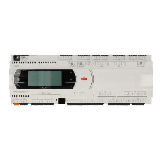
pCO5+
Programmable Controller
User manual
NO POWER
& SIGNAL
CABLES
TOGETHER
READ CAREFULLY IN THE TEXT!
I n t e g r a t e d
C o n t r o l
S o l u t i o n s
&
E n e r g y
S a v i n g s
Related Manuals for Carel pCO5+
Summary of Contents for Carel pCO5+
-
Page 1
pCO5+ Programmable Controller User manual NO POWER & SIGNAL CABLES TOGETHER READ CAREFULLY IN THE TEXT! I n t e g r a t e d C o n t r o l S o l u t i o n s &… -
Page 3
The technical specifi cations shown in the manual may be changed without prior warning. The liability of CAREL in relation to its products is specifi ed in the CAREL general contract conditions, available on the website www.CAREL.com and/or by specifi c agreements with customers;… -
Page 4
pCO5plus +0300020EN rel. 1.2 — 07.11.2013… -
Page 5: Table Of Contents
Content 1. INTRODUCTION 8. TECHNICAL SPECIFICATIONS Programmability ………………..7 pCO5+ Technical Specifi cations …………..46 Functional layout ………………..8 Conformity to standards …………….50 Terminals……………………9 Models ……………………50 BMS port expansion cards …………….9 Connectors ………………….50 Fieldbus port expansions cards ……………10 9. APPENDIX External modules ………………..11 Smart Key: operating instructions …………51 2.
-
Page 6
pCO5plus +0300020EN rel. 1.2 — 07.11.2013… -
Page 7: Introduction
— NO or NC relay outputs; available on the market. — USB ports; — optically-isolated/non-optically-isolated built-in serial ports; The pCO5+ controller has been developed by CAREL to provide solutions — built-in display. • to a host of applications in air-conditioning, refrigeration and HVAC/R in various kinds of connectors (spring, screw, etc.).
-
Page 8: Functional Layout
1.2 Functional layout The fi gure below shows the functional layout of an air handling unit. Damper actuators and valve actuators are fi eld devices that communicate through Fieldbus 1 (ref. C). Fieldbus 2 (ref. E) is the medium through which the serial probes communicate the values measured, and through which the humidifi…
-
Page 9: Terminals
Terminals Note: All instruction sheets can be downloaded from www.carel. com in the “Documentation” section. Code Description Notes The pGD Touch 4.3” graphics terminal belongs to the family of touchscreen terminals, PGDT04000F*** designed to simplify and make more intuitive the interfacing of users with the controllers pGD Touch 4.3”…
-
Page 10: Fieldbus Port Expansions Cards
Allows connecting to a LonWorks® TP/FT 10 network. The program resides in the fl ash PCO10000F0 memory located in the socket, and can be programmed directly via the LonWorks® LonWorks® interface network using network installation and maintenance tools such as LonMaker™. (tech.
-
Page 11: External Modules
• can be connected to the CPY terminal (code CPYTERM*) or to the supervisor network with Modbus® RTU or proprietary CAREL protocol. PCOUMI2000 Allows checking the main parameters of humidifi ers for OEM made by CAREL di- Interface for OEM rectly from the pCO controller. The values measured by the sensors (high level, (tech.
-
Page 12: Design
2. DESIGN On the models where they are included, the front panel contains a display and a keypad with 6 backlit buttons that, when pressed individually or in combination, allow the following operations: • uploading an application program; • commissioning. During regular operation and depending on the application program installed, the terminal can be used: •…
-
Page 13: Communication Ports
3. COMMUNICATION PORTS 3.1 Serial ports Compared to the pCO3, pCO5+ (and pCO5) controllers have a second BMS serial port on connector J25 (BMS2) and a second Fieldbus port on connector J26 (FBus2). pCO5+ Large and Extralarge boards still have connector J23, which is marked FBus2 like connector J26.
-
Page 14: Port J26 Confi Guration
RS485 Fieldbus port are, due to the nature of the port, Master protocols (CAREL Master or Modbus RTU Master), although in special cases Slave protocols can be used (CAREL Slave or Modbus RTU Slave), adopting the necessary measures. Likewise, Slave protocols are applied on the RS485 BMS port, although under certain conditions Master protocols can also be used.
-
Page 15: Installation
INSTALLATION 4.1 Mounting on DIN rail and dimensions The controller is designed to be mounted on a DIN rail. The fi gure below shows the dimensions for each size. Mounting: • place the controller on the DIN rail and press it down gently. The tabs at the back will snap into place and lock the controller.
-
Page 16: Preliminary Operations
Non-optically-isolated serial port • Use only optional boards and connectors supplied by CAREL. This is the case of the serial ZERO — pLAN (J11), Fieldbus 2 (J23 and J26) and BMS2 if not optically isolated (on models with built-in ports that are not optically isolated).
-
Page 17
Case 1: Multiple boards connected to a Master/Slave network powered Optically-isolated serial port by the same transformer. This is a typical application of multiple boards This is the case of serial ONE — BMS1, serial TWO — Fieldbus 1 and the built- connected inside the same electrical panel. -
Page 18: Connecting The Terminal
The typical connection for one terminal (e.g. PGD1) is made using a Case B: 2 terminals 6-pin telephone cable available from CAREL as an accessory (code Two terminals can be directly connected only on a Small model. Models S90CONN00*). The telephone connector provides both data transmission of other sizes require the second terminal to be powered separately.
-
Page 19: Input/Output Labels
B.2 Distance 50< L< 200 m. 2: pCO controller in pLAN network Use 3 TCONN6J000 boards connected as shown in the fi gure. If a terminal is connected to a pCO controller which is itself connected to other controllers in a pLAN network, the terminal is directly powered L <…
-
Page 20: I/O Table
4.7 I/O table pCO5+ Controllers pCOE I/O expansion card NTC input In Universal I/O In Analogue input(*) PTC input In Universal I/O PT500 input In Universal I/O PT1000 input In Universal I/O PT100 input max 2 max 3 max 4 max 3 max 3 In Universal I/O…
-
Page 21: Small And Medium Pco5+: Connecting Terminals
4.8 Small and Medium pCO5+: connecting terminals 13 14 J1 5 J1 2 J1 3 J1 4 J11 pLAN J2 5 BMS2 J2 6 FBus2 FieldBus card B M S card Fig. 4.q J1 7 J1 2 J1 3 J1 4 J11 pLAN J2 5 BMS2 J2 6 FBus2…
-
Page 22: Large And Extralarge Pco5+: Connecting Terminals
4.9 Large and Extralarge pCO5+: connecting terminals N.C. Model J11 pLAN J23 FBus2 J25 BMS2 J26 FBus2 N.O. Model FieldBus card B M S card Fig. 4.s J11 pLAN J23 FBus2 J25 BMS2 J26 FBus2 FieldBus card B M S card Fig.
-
Page 23: Pco5+ With Built-In Driver: Connecting Terminals
4.10 pCO5+ with built-in driver: connecting terminals pCO5+ controllers come in two models, with one or two built-in drivers for electronic expansion valves. J11 pLAN J25 BMS2 J26 FBus2 driver FieldBus card B M S card Fig. 4.u Ref. Description Ref.
-
Page 24: Pco5+ Terminals Description
4.12 pCO5+ terminals description Ref. Term. Label Description J12-1 Common for relays 1, 2, 3 Please refer to the fi gures in the preceding pages regarding the pCO5+. J12-2 Normally open contact, relay 1 J12-3 Normally open contact, relay 2 J12-4 Normally open contact, relay 3 J12-5…
-
Page 25
Only for pCO5+ built-in driver: J27-1 Electronic expansion valve 1 control (see “Electro- J27-2 J27-3 nic valve connection”). J27-4 J28-1 J28-2 Electronic expansion valve 2 control (see “Electro- J28-3 nic valve connection”). J28-4 J30-1 VBAT J30-2 Power from external Ultracap module J30-3 J29-1 Common for power supply to probes… -
Page 26: Input/Output Connections
INPUT/OUTPUT CONNECTIONS 5.1 Power supply Max. number of connectable analogue inputs The maximum number of analogue inputs that can be connected to the The fi gure below shows the power supply connection diagram. Use universal inputs/outputs depends on the type used. a class II safety isolating transformer with short-circuit and overload protection.
-
Page 27
For details on the operating range see the data sheets supplied with the probes. The controller can be connected to all the CAREL DP* series active temperature input: 24 V 50…60 Hz / 28…36 V max. power: 45 VA/20 W… -
Page 28
The controller can be connected to all CAREL SPK* series active pressure FieldBus card B M S card probes or any commercially available pressure probes with 0 to 20 mA or 4 to 20 mA signals. -
Page 29: Digital Inputs
Connecting fast digital inputs 5.3 Digital inputs The controller features digital inputs for connecting safety devices, Important: The wires connecting the fast digital inputs/counters alarms, device status indicators and remote switches. These inputs are all optically isolated from the other terminals. They can work at 24 Vac (+10/- must be shielded to avoid causing electromagnetic interference with the 15%) or at 28 to 36 Vdc (-20/+10%) (indicated with ID*), and some also at probe cables.
-
Page 30
Example of connection diagram (LARGE model): J1 9 FieldBus card B M S card 24 Vac Fig. 5.m FieldBus card B M S card 24 Vac Fig. 5.n 24 Vdc digital inputs The ID… digital inputs can be controlled at 24 Vdc. Example of connection diagram (LARGE model): input: 24 V 50…60 Hz / 28…36 V max. -
Page 31: Optically-Isolated Analogue Outputs
230 Vac digital inputs Medium and Extralarge models feature one group of 230 Vac inputs (terminal J8), while Large models have two groups (on terminals J8 and J19). Each group consists of two digital inputs that can be powered at 230 Vac, indicated with IDH*, and two inputs that can be powered at 24 Vac/ Vdc, indicated with ID*.
-
Page 32
Example of connection diagram (LARGE model): eldBus card B M S card Vout Vout Vout Vout 24 Vac / 28…36 Vdc Vout Vout Fig. 5.s Max. number di optically-isolated analogue outputs (reference VG0) pCO5+ model Small/Medium/Extralarge Large Outputs Y1, Y2, Y3, Y4 Y1, Y2, Y3, Y4, Y5, Y6 pCO5plus +0300020EN rel. -
Page 33: Connecting The Electronic Valve
Fbus2 port (J26) must have the same communication protocol (CAREL Standard Master or Modbus® Master), the same baud rate, stop bits and parity. The CAREL or Modbus protocol is selected automatically. The internal driver’s address is 198 (EVD Evolution’s default…
-
Page 34: Digital Outputs
5.6 Digital outputs RELAY GROUPS FOR CONSECUTIVE COMMANDS (~100 ms) Electromechanical relay digital outputs pCO5+ pCO5+ Extra- The controller features digital outputs with electromechanical relays. For Large Large ease of installation, the common terminals of some of the relays have 9, 10, 11, 14, 15, 16, 14, 15, 16, 17,…
-
Page 35: General Connection Diagram
1 (0/5 V) +5 V probe 2 (4/20 mA) probe 3 (0/1 Vdc or 4/20 mA) +VDC probe 4 Carel NTC probe 5 PT1000 digital output 1 digital output 2 digital output 3 analog output 1 (0…10 Vdc) analog output 2 (0…10 Vdc)
-
Page 36: Start-Up
NC14 NC14 pGDE/pGD1 Shared ID15H NO15 ID15H NO15 IDC1 IDC1 ID15 ID15 IDC15 IDC15 NC15 CAREL devices in a pCO local area network (pLAN) without requiring NC15 ID16 ID16 ID16H ID16H NO10 NO16 NO10 NO16 ID10 ID10 NO11 NO17 NO11…
-
Page 37: Setting The Terminal’s Address And Connecting The Controller To The Terminal
Setting the pLAN address Power off the controller. Procedure: Press button A for 5 seconds; the pLAN address starts fl ashing. Press repeatedly or hold the button until reaching the desired address (e.g. 7), then remove the screwdriver. J11 pLAN Wait until the address starts fl…
-
Page 38: Uploading Software
fi les to the NAND fl ash memory. establish the connection. The terminal can be either private or shared. As a rule, CAREL advises NOT to update the BOOT; CAREL always loads the BOOT best suited for the controller’s operation during construction. Only Smart key in very special cases will CAREL ask the user to update the BOOT.
-
Page 39: Checking The Software Installed And Other Information
NAND fl ash memory Upload and Download UPLOAD can be performed in three diff erent ways: This type di memory is included on all pCO5+ controller versions. pCO Manager can be used to load any type of fi le to the NAND fl ash memory. manual mode: the user selects manual mode from the keypad, then It can be used, for example, to save the source fi…
-
Page 40
M E M O R I E S S T A T U S The ID number is a code, diff erent for each pCO manufactured by CAREL, and is available for use in future applications. Not all pCO units are given an ID number by CAREL;… -
Page 41: Application Diagrams
APPLICATION DIAGRAMS The following are a series of diagrams illustrating which devices can be Heat pump connected to the pCO5+ and the accessory cards required, depending Power + on the type of application. PGD1* PSD0* PGD Touch Air handling unit CP*: schede controllo CP*: KUE humidifi…
-
Page 42
Chiller — Screw compressor To manage two refrigerant circuits, there are two options. Case 1: 2 pCO5 Medium controllers and pCO5+ with built-in electronic expansion valve driver. dispositivi dispositivi dispositivi Device Device Device PGD1* terze parti terze parti terze parti PGD1* PGD Touch INVERTER… -
Page 43
pCO5plus +0300020EN rel. 1.2 — 07.11.2013… -
Page 44: Devices That Can Be Connected To The Pco5
— pGD1 terminal pGD2 — pGD3 terminal Aria terminal pCO in pLAN FCM series controllers EVD200 EVD Evolution CAREL slave devices (tLAN) CAREL slave devices (485) pCOexp 485 pCOexp tLAN μChiller2 expansion Hydronic fan coil and CANbus PlantVisorPRO local…
-
Page 45
Modbus Slave If Modbus Slave is active then CAREL Slave can be activated only on another serial port. The second Modbus extended on BMS2 (with 10000 integer variables) can work at the same time as the one activated on the other ports. -
Page 46: Technical Specifications
TECHNICAL SPECIFICATIONS 8.1 pCO5+ Technical Specifi cations SMALL 13 DIN modules 110 X 227,5 X 60 mm Dimensions MEDIUM, LARGE, EXTRALARGE 18 DIN modules 110 X 315 X 60 mm BUILT-IN DRIVER 18 DIN modules 110 X 315 X 75 mm Mounting Can be mounted on DIN rail in accordance with DIN 43880 and IEC EN 50022 Material…
-
Page 47
MEDIUM/ BUILT-IN DRIVER/ SMALL LARGE EXTRALARGE — CAREL NTC probes (-50T90°C; R/T 10 kΩ±1% at 25°C) — NTC HT (0T150°C) — PTC (600Ω to 2200Ω) — PT500 (-100T300°C) — PT1000 (-100T400°C) 4 (2 on U1 to U5, 3 (2 on U1 to U5, — PT100 probes (-100T400°C) -
Page 48
Type 0 to 10 V optically-isolated on Y1 to Y6 Lmax 30 m SMALL, MEDIUM/ BUILT-IN DRIVER/EXTRALARGE Y1…Y4 a 0…10 V Maximum number Analogue outputs LARGE Y1…Y6 a 0…10 V Power supply External 24 Vac (+10/-15%) or 28 to 36 Vdc on VG(+), VG0(-) (*) Accuracy Y1…Y6 ±2% full scale… -
Page 49
CAREL: Two CAREL EXVs as for EVD EVOLUTION TWIN SPORLAN: SER(I) G, J, K Shielded 4-wire cable CAREL code E2VCABS*00, or AWG22 shielded 4-wire cable Lmax =10 m, or AWG14 shielded 4-wire cable Lmax = 50 Motor connection Digital input Digital input to be activated with voltage-free contact or transistor to GND. -
Page 50: Conformity To Standards
P+5****C***** Optically-isolated BMS2/Optically-isolated Fieldbus2 P+5***0****** No USB port USB port P+5***A****** USB port P+5******0*** Without valve driver Valve P+5******1*** 1 CAREL valve driver driver P+5******2*** 2 CAREL valve drivers P+5*******0** Without terminal Built-in P+5*******E** Con PGD1 terminal terminal P+5********S* Small…
-
Page 51: Appendix
9. APPENDIX 9.1 Smart Key: operating instructions Meanings of Buttons/Symbols Flashing: The key is connecting to the pCO. During this phase, which may last a few seconds, the start button is disabled. start Flashing: The key has detected the pCO and is checking the access rights.
-
Page 52: Pco Manager: Operating Instructions
Installing pCO Manager Go to http://ksa.carel.com and, in the section pCO Sistema, select pCO_ manager. After you accept the general conditions of the software’s free use licence, a window will open from which you can download the fi le pCO_manager.zip.
-
Page 53
2) Enter the new value (e.g. 3) and click OK. The new value will appear in When the user has fi nished using Commissioning, whether for confi guration the column marked “scritto” [written]. To write the parameter to the pCO or monitoring purposes, the following fi… -
Page 54: Pendrive: Operating Instructions
Menu access 9.3 Pendrive: operating instructions The following are the steps for accessing the pendrive management menu. Procedure: File extensions, names and contents Connect the pendrive to the master port. Various types of fi les can be uploaded and downloaded and are distinguished by their extension.
-
Page 55
UPLOAD non-volatile memory (.dev) Upload non volatile memory carel.com (.os file), unzip the .os file; UPLOAD the entire contents of the pCO Copy pCO upload • the [IUP] label can be followed by one or more “.iup” files. -
Page 56
Confi rm by selecting Prg. A screen is displayed requesting The display fl ashes to indicate that after loading the new BIOS the confi rmation to upload the non-volatile memory. Press Enter to controller is being reset. confi rm. Fig. 9.p Fig. -
Page 57
Download As mentioned above, the DOWNLOAD operation can be managed in two ways: Manual mode: follow the steps described in the paragraph “Automatic upload” and select manual operation. Then each fi le must be selected and downloaded. Autorun mode: prepare a fi le called “autorun.txt”, containing a string that identifi… -
Page 58: Confi Guring Pcoweb/Pconet From A System Screen
When you select “PCONET settings” the following screen will appear: usual tools, i.e. BACset or web interface (pCOWeb only). Confi guration can be done either when using the Modbus protocol or the CAREL B A C n e t I D : protocol, but only on the BMS1 serial port.
-
Page 60
Agenzia / Agency: CAREL INDUSTRIES — Headquarters Via dell’Industria, 11 — 35020 Brugine — Padova (Italy) Tel. (+39) 049.9716611 — Fax (+39) 049.9716600 e-mail: carel@carel.com — www.carel.com…
инструкцияCarel pCO5

Integrated Control Solutions & Energy Savings
pCO
5
NO POWER
& SIGNAL
CABLES
TOGETHER
READ CAREFULLY IN THE TEXT!
programmable controller
User Manual
Посмотреть инструкция для Carel pCO5 бесплатно. Руководство относится к категории без категории, 3 человек(а) дали ему среднюю оценку 7.6. Руководство доступно на следующих языках: английский. У вас есть вопрос о Carel pCO5 или вам нужна помощь? Задайте свой вопрос здесь
Нужна помощь?
У вас есть вопрос о Carel а ответа нет в руководстве? Задайте свой вопрос здесь Дай исчерпывающее описание проблемы и четко задайте свой вопрос. Чем детальнее описание проблемы или вопроса, тем легче будет другим пользователям Carel предоставить вам исчерпывающий ответ.
Анатолий • 2-5-2023Нет комментариев
Как сбросить ошибку 90 на pco5+,?
Количество вопросов: 1

Главная
Не можете найти ответ на свой вопрос в руководстве? Вы можете найти ответ на свой вопрос ниже, в разделе часто задаваемых вопросов о Carel pCO5.
Инструкция Carel pCO5 доступно в русский?
Не нашли свой вопрос? Задайте свой вопрос здесь
-

Carel
Руководство пользователя. Программируемые электронные контроллеры pCO1
-
Carel
Техническое описание электронных контроллеров pCO3 для управления на базе микропроцессора, программно и аппаратно совместимого с рядом устройств серии pCO2.
-
Carel
Обновление программы pCO через pCOWeb. Справочное руководство.
-
Carel
Инструкция по эксплуатации и програмированию микропроцессорных контроллеров для чиллеров и тепловых насосов pCO.
-
Carel
Руководство по эксплуатации модулей расширения pCO: pCOB, pCO2, pCO1 и pCOC I/O
-
Carel
Руководство по эксплуатации программируемых электронных контроллеров pCOXS
-
Carel
Программируемые электронные контроллеры pCOXS. Руководство пользователя.
-
Carel
Руководство по эксплуатации электронных контроллеров pCO3 (обзор)
-
Carel
Руководство по эксплуатации электронных контроллеров pCO3
-
Carel
Руководство по эксплуатации контроллеров pCO2-pCO sistema
-
Carel
Руководство по эксплуатации программируемых электронных контроллеров pCO2 для приложений в области кондиционирования воздуха и холодильного оборудования.
-
Carel
Руководство пользователя. Программируемые электронные контроллеры pCO2 для приложений в области кондиционирования воздуха и холодильного оборудования.


Контроллер pCO5 представляет собой электронный контроллер на базе микропроцессора, аппаратно и программно совместимый с контроллерами семейства pCO3, и предназначен для применения в системах кондиционирования воздуха и охлаждения. Такие контроллеры универсальны и предусматривают возможность разработки отдельных изделий по требованиям заказчика. Контроллеры pCO5 работают под управлением программы и комплектуются набором контактов для подключения различных устройств — компрессоры, вентиляторы и так далее. Программа и текущие параметры хранятся на флэш-памяти и памяти E2PROM, таким образом, сохранность всех данных гарантируется даже при сбоях в электропитании без необходимости применения резервной батареи.
Документация
Контроллер pCO5 предусматривает возможность подключения по сети pLAN (pCO Local Area Network) к другим контроллерам pCO5, а также любым другим контроллерам семейства pCO sistema и терминалам семейства pGD. Каждый контроллер, включенный в сеть pLAN, может обмениваться любыми цифровыми и аналоговыми переменными в зависимости от используемой прикладной программы. Для эффективного обмена данными можно включить до 32 устройств (контроллеров pCO и терминалов). В отличие от других контроллеров pCO, контроллер pCO5 комплектуется двумя дополнительными встроенными последовательными разъемами RS485: FieldBus и BMS. При использовании встроенного последовательного порта или наличии опциональной платы последовательного интерфейса контроллер pCO5 обеспечивает возможность подключения
к системе управления зданием (BMS) по линии RS485 и протоколу передачи данных CAREL или Modbus. Производитель также предлагает другие опциональные платы для подключения к системе диспетчеризации по другим интерфейсам, кроме RS485. Наконец, при помощи опциональной или встроенной платы контроллер можно подключить через последовательный порт FieldBus к низовой автоматике (например: клапаны, плату расширения входов/выходов pCOe, внешние драйверы электронных клапанов и т. д.). Конструктив pCO5 предусматривает следующие опциональные варианты компоновки контроллера: модели со встроенным драйвером вентиля EVD EVO, single или twin, которые можно наращивать опциональным модулем Ultracap, который обеспечивает электропитание привода вентиля в экстренных ситуациях.
| Условия хранения | от -40 до 70 °C, 90 % отн. влажность, без конденсата |
| Условия работы | от -25 до 60 °C, 90 % отн. влажность, без конденсата |
| Класс защиты | IP20, IP40 – только модели без модуля Ultracap |
| Вред окружающей среде | 2 |
| Класс безопасности (электрический разряд) | модели без драйвера вентиля интегрируются в системы класса 1 и/или 2, а модели с драйвером вентиля в системы класса 1 |
| Коэффициент PTI изоляционных материалов | печатная плата: PTI 250; изоляционный материал: PTI 175 |
| Период электр. напряженности между изолирующими частями | длинный |
| Тип действия | 1C; 1Y для моделей с твердотельными реле |
| Тип рассоединения или микрокоммутации | микрокоммутация |
| Термо- и огнепрочность | категория D (UL94 – V2) |
| Стойкость к скачкам напряжения | Категория сверхнапряжения: II для всех входов/выходов кроме цифровых выходов высокого напряжения и цифровых входов (цепи класса II) — для них будет категория I |
| Характеристики старения (часы наработки) | 80 000 |
| Кол-во циклов автоматической коммутации | 100 000 (EN 60730-1); 30 000 (UL 873) |
| Структура и класс ПО | класс A |
| Устойчивость к скачкам напряжения (IEC EN 61000-4-5) | категория 3 |
| Электропитание (контроллер с подключенным терминалом) | Модели без встроенного драйвера вентиля: 24 В пер. т. +10/-15 %, 50–60 Гц и 28–36 В пост. т. +10/-20 % ток не более 45 В•А/20 Вт Модели со встроенным драйвером вентиля с/без модуля Ultracap: 24 В пер. т. +10/-15 % 50–60 Гц ток не более: 80 В•А/35 Вт (90ВА / 40Вт во время зарядки модуля Ultracap) |
| Центральный процессор | H8SX1651, 32 бит, 44 МГц |
| Память (FLASH MEMORY) | 4Мб (8Мб в старшей модели). Также доступны версии с расширенной до 32 Mб NAND Flash |
| Память данных (статическое ОЗУ) | 512 кБ при 16 бит (296 кБ БИОС; 216 кБ приложения) |
| Память параметров | 13 кБ при 16 бит (не более: 100 000 циклов записи на сектор памяти) + 32 кБ E2PROM (недоступно для pLAN) |
| Время цикла (приложения средней сложности) | 0,2 с (типичное значение) |
| Часы с батарейкой | стандартные |
| Точность часов | 100 ppm |
View a manual of the Carel pCO5 below. All manuals on ManualsCat.com can be viewed completely free of charge. By using the ‘Select a language’ button, you can choose the language of the manual you want to view.
Page: 1
3
ENG
“pCO5”+0300009EN rel. 1.2 — 24.04.2014
WARNINGS
CAREL bases the development of its products on decades of experience
in HVAC, on the continuous investments in technological innovations
to products, procedures and strict quality processes with in-circuit and
functional testing on 100% of its products, and on the most innovative
production technology available on the market. CAREL and its subsidiaries
nonetheless cannot guarantee that all the aspects of the product and the
software included with the product respond to the requirements of the final
application, despite the product being developed according to start-of-the-
art techniques.
The customer (manufacturer, developer or installer of the final equipment)
accepts all liability and risk relating to the configuration of the product in
order to reach the expected results in relation to the specific final installation
and/or equipment.
CAREL may, based on specific agreements, acts as a consultant for the positive
commissioning of the final unit/application, however in no case does it accept
liability for the correct operation of the final equipment/system.
The CAREL product is a state-of-the-art product, whose operation is specified
in the technical documentation supplied with the product or can be
downloaded, even prior to purchase, from the website www.carel.com.
Each CAREL product, in relation to its advanced level of technology, requires
setup/configuration/programming/commissioning to be able to operate in
the best possible way for the specific application.The failure to complete such
operations, which are required/indicated in the user manual, may cause the
final product to malfunction; CAREL accepts no liability in such cases.
Only qualified personnel may install or carry out technical service on the
product.
The customer must only use the product in the manner described in the
documentation relating to the product.
In addition to observing any further warnings described in this manual, the
following warnings must be heeded for all CAREL products:
• Prevent the electronic circuits from getting wet. Rain, humidity and all
types of liquids or condensate contain corrosive minerals that may damage
the electronic circuits. In any case, the product should be used or stored
in environments that comply with the temperature and humidity limits
specified in the manual.
• Do not install the device in particularly hot environments. Too high
temperatures may reduce the life of electronic devices, damage them and
deform or melt the plastic parts. In any case, the product should be used
or stored in environments that comply with the temperature and humidity
limits specified in the manual.
• Do not attempt to open the device in any way other than described in the
manual.
• Do not drop, hit or shake the device, as the internal circuits and mechanisms
may be irreparably damaged.
• Do not use corrosive chemicals, solvents or aggressive detergents to clean
the device.
• Do not use the product for applications other than those specified in the
technical manual.
All of the above suggestions likewise apply to the controllers, serial boards,
programming keys or any other accessory in the CAREL product portfolio.
CAREL adopts a policy of continual development. Consequently, CAREL
reserves the right to make changes and improvements to any product
described in this document without prior warning.
The technical specifications shown in the manual may be changed without
prior warning.
TheliabilityofCARELinrelationtoitsproductsisspecifiedintheCARELgeneral
contract conditions, available on the website www.carel.com and/or by
specific agreements with customers; specifically, to the extent where allowed
by applicable legislation, in no case will CAREL, its employees or subsidiaries
be liable for any lost earnings or sales, losses of data and information, costs of
replacement goods or services, damage to things or people, downtime or any
direct, indirect, incidental, actual, punitive, exemplary, special or consequential
damage of any kind whatsoever, whether contractual, extra-contractual or
due to negligence, or any other liabilities deriving from the installation, use or
impossibility to use the product, even if CAREL or its subsidiaries are warned
of the possibility of such damage.
DISPOSAL
INFORMATION FOR USERS ON THE CORRECT HANDLING OF WASTE
ELECTRICAL AND ELECTRONIC EQUIPMENT (WEEE)
In reference to European Union directive 2002/96/EC issued on 27 January
2003 and related national legislation, please note that:
1. WEEE cannot be disposed of as municipal waste and such waste must
be collected and disposed of separately.
2. The public or private waste collection systems defined by local
legislation must be used. In addition, the equipment can be returned
to the distributor at the end of its working life when buying new
equipment.
3. The equipment may contain hazardous substances: the improper use or
incorrect disposal of such may have negative effects on human health
and on the environment.
4. The symbol (crossed-out wheeled bin) shown on the product or on the
packaging and on the instruction sheet indicates that the equipment
has been introduced onto the market after 13 August 2005 and that it
must be disposed of separately.
5. In the event of illegal disposal of electrical and electronic waste, the
penalties are specified by local waste disposal legislation.
Warranty on materials: 2 years (from the date of production, excluding
consumables).
Approval: the quality and safety of CAREL INDUSTRIES Hq products are
guaranteed by the ISO 9001 certified design and production system, as well
as by product marking.
WARNING: separate as much as possible the probe and digital input cables
from the cables carrying inductive loads and power cables to avoid possible
electromagnetic disturbance. Never run power cables (including the electrical
panel cables) and signal cables in the same conduits.
NO POWER
& SIGNAL
CABLES
TOGETHER
READ CAREFULLY IN THE TEXT!
Page: 2
5
ENG
“pCO5”+0300009EN rel. 1.2 — 24.04.2014
Content
1. INTRODUCTION AND GENERAL FEATURES 7
1.1 Programmability…………………………………………………………………………………….7
2. PRODUCT DESCRIPTIONS 8
2.1 pCO5
controller………………………………………………………………………………………8
2.2 Meaning of the pCO5
inputs/outputs ………………………………………….9
2.3 pCO5
technical specifications ………………………………………………………10
2.4 Dimensions……………………………………………………………………………………………15
2.5 pCO compact……………………………………………………………………………………….16
2.6 Meaning of the pCO5
compact inputs/outputs………………………16
2.7 pCO5
compact compact technical specifications………………….17
2.8 pCO5
compact dimensions……………………………………………………………..19
3. USER TERMINALS AND OPTIONAL CARDS 20
3.1 Graphic terminals …………………………………………………………………………….20
3.2 Optional cards for pCO sistema …………………………………………………….21
3.3 Connectors…………………………………………………………………………………………….25
4. PCO CONTROLLER INSTALLATION 26
4.1 General installation instructions……………………………………………………26
4.2 Power supply………………………………………………………………………………………..26
4.3 Connecting the analogue inputs………………………………………………….27
4.4 Fast digital inputs………………………………………………………………………………..29
4.5 Connecting the digital inputs………………………………………………………..30
4.6 Connecting the analogue outputs………………………………………………32
4.7 Connecting the digital outputs……………………………………………………..34
5. PLAN NETWORK CONFIGURATION 36
5.1 Introduction ………………………………………………………………………………………….36
5.2 pGDE/pGD1 terminal installation…………………………………………………38
5.3 pLAN address configuration on pCO5 and pCO5 compact…….39
5.4 pLAN electrical connections on the pCO………………………………….41
5.5 Remote terminal with pLAN network…………………………………………42
5.6 pLAN network technical specifications………………………………………43
6. PCO5
SERIAL CONNECTIONS 44
6.1 pCO5
serial connections: differences compared to pCO3
….44
7. UPDATES, FIRMWARE AND LOG FILES
FOR PCO CONTROLLERS 54
7.1 pCO Manager……………………………………………………………………………………….54
7.2 USB port (on pCO5
and pCO5
compact models
where featured)……………………………………………………………………………………54
7.3 Smartkey…………………………………………………………………………………………………59
7.4 NAND Flash memory ………………………………………………………………………..59
7.5 Checking the software installed on the pCO
and other information……………………………………………………………………….59
8. GENERAL CONNECTION DIAGRAMS 62
8.1 pCO5
………………………………………………………………………………………………………..62
8.2 pCO5
with built-in EVD evo……………………………………………………………..63
9. TROUBLESHOOTING 64
Page: 3
7
ENG
“pCO5”+0300009EN rel. 1.2 — 24.04.2014
1. INTRODUCTION AND GENERAL FEATURES
pCO sistema: CAREL’s proposal for programmable controllers.
It consists of programmable controllers, user interfaces, gateways and
communication interfaces, and remote management systems to offer
the HVAC/R market a control system that’s powerful, flexible and easy
to interface to the most commonly-used building management systems.
pCO sistema is very reliable and can be easily customised to differentiate
the air-conditioning or refrigeration unit control system.
All versions of these controllers use a 32-bit microprocessor and either
4 or 8 MBytes of memory so as to ensure high performance in terms of
speed and memory space available. The pCO sistema controllers also
come in different sizes according to the number of inputs and outputs,
giving the best price/performance ratio. Given the increasing need for
integration, the pCO sistema family controllers can interface with some
of the most commonly-used serial communication standards, and when
fitted with optional cards can be integrated into BMS systems.
The pCO* family can connect different types of sensors (e.g. ratiometric,
NTC, 4 to 20 mA, etc.); a built-in terminal is available; there are one or two
serial ports (depending on the model) to offer connection to controlled
field devices (valves, I/O expansions, electronic valve drivers…). In
addition, on models where featured, the controllers have 2 USB ports for
uploading and downloading files.
All these features place our controllers at a level of excellence in fulfilling
the needs of the HVAC/R market.
1.1 Programmability
The CAREL pCO sistema controllers can be programmed using 1Tool
development software, offering the following advantages:
• software portability on different CAREL hardware. applications
developed for the pCO can be simply and quickly transferred to
another hardware platform and vice-versa, modifying only the inputs
and outputs;
• rapid development, at competitive costs, of custom programs;
• reliability guaranteed by the use of standard routines, tested in the
field.
The use of 1Tool, moreover, ensures the customer the maximum level of
privacy and self-management when developing new programs on their
own. The possibility to use the same hardware for different applications
allows standardisation, with the clear advantages of being able to feature
in-circuit and functional testing and burn-in procedures on all of the
products and consequently reach a high level of reliability, both overall
and in terms of the individual electronic components.
1Tool: exclusive, easy to use CAREL development software for
programming, simulation, supervision and definition of pLAN networks
using CAREL terminals and pCO programmable controllers.
Applications
TheprogrammabilityofthepCOensuresabsoluteflexibilityofapplication.
The same standard hardware can be used to control:
• chillers and heat pumps;
• roof-top units;
• air-conditioners;
• small/medium-sized air handling units (on request);
• showcases (on request and to specifications);
• cold rooms (on request and to specifications);
• curing rooms;
• compressor racks;
• universal stage controllers.
Other types of programs can be developed to specific customer
requirements.
Hardware architecture
The pCO architecture features:
• the pCO controller, fitted with a 32-bit microprocessor for running the
control program, and the set of terminals required for connection to
the controlled devices (for example: valves, compressors, fans). The
program and the parameters are saved permanently in the FLASH
memory, preventing data loss in the event of power failure (without
requiring a backup battery). The pCO also allows connection to a local
pLAN network made up of a series of pCO boards and terminals. Each
board can exchange information (any variable, digital or analogue,
according to the application software) at high transmission speeds.
connection to the supervisor/telemaintenance serial line, over the
RS485 standard, is made using the optional serial cards (PCO004850)
and the CAREL or Modbus® communication protocol.
• The terminal, also managed by microprocessor, fitted with display,
keypad and LEDs to allow the programming of the control parameters
(set point, differential band, alarm thresholds) and basic functions by
the user (ON/OFF, display of the controlled values, optional printing).
The terminal does not have to be connected to the pCO for normal
operation, but can be used for the initial programming of the funda-
mental parameters.
The power of the application software means that the user terminal
allows:
• initial programming of the unit, with password-protected access;
• the possibility to modify, at any time, the fundamental operating
parameters, optionally protected by password;
• display and audible signalling (by buzzer) of any alarms;
• display of the active functions by LED;
• display of all the values measured.
Page: 4
8
ENG
“pCO5”+0300009EN rel. 1.2 — 24.04.2014
2. PRODUCT DESCRIPTIONS
2.1 pCO5
controller
Large Version
C1
NO1
NO2
NO3
C1
C4
NO4
NO5
NO6
C4
C7
NO7
C7
NO8
C8
NC8
NO12
C12
NC12
NO13
C13
NC13
C9
NO9
NO10
NO11
C9
G
G0
B1
B2
B3
GND
+VDC
+V
term
GND
+5
V
REF
B4
BC4
B5
BC5
VG
VG0
Y1
Y2
Y3
Y4
ID1
ID2
ID3
ID4
ID5
ID6
ID7
ID8
IDC1
B6
B7
B8
GND
ID9
ID10
ID11
ID12
IDC9
ID13H
ID13
IDC13
ID14
ID14H
J1
10
1
11
J24 J2 J3 J4 J5 J7
J8
J20
J21
J14
J11 pLAN
J10
J9
J13
J12
J22
J16 J17 J18
J15
J6
J19
3
7
7
4
4
6
5
NO14
C14
NC14
NO15
C15
NC15
C16
NO16
NO17
NO18
C16
8
9
2
13
ID15H
ID15
IDC15
ID16
ID16H
Y5
Y6
ID17
ID18
IDC17
B9
BC9
B10
BC10
16
15
14
FieldBus card BMS card
8
6
5
7
12
11
17
J25 BMS2 J26 FBus2
18
19
J23 FBus2
input: 24 V 50…60 Hz / 28…36 V
max. power: 45 VA/20 W
Fig. 2.a
ExtraLarge Version
NO6
C4
7
rd J20
J21 J22
J19
C14
NO14
NO15
NO16
C14
C17
NO17
NO18
NO19
NO20
C17
C25
NO25
NO26
NO27
NO28
NO29
C25
C21
NO21
NO22
NO23
NO24
C21
11
12
J23 FBus2
Fig. 2.b
Version with VALVE DRIVER
NO4
NO5
NO6
C4
Y3
Y4
J13
al card J29
J27
J30
1
3
2
4
J28
1
3
2
4
J16
C9
NO9
NO10
NO11
C9
J15
NO8
C8
NC8
J17
NO12
C12
NC12
J18
NO13
C13
NC13
GND
VREF
S1
S2
S3
S4
DI1
DI2
J8
ID13H
ID13
IDC13
ID14
ID14H
J7
ID9
ID10
ID11
ID12
ICC9
J6
B6
B7
B8
GND
VBAT
G0
G
21
22
20
driver
J5
ID1
ID2
ID3
ID4
ID5
ID6
ID7
ID8
IDC1
Fig. 2.c
Page: 5
9
ENG
“pCO5”+0300009EN rel. 1.2 — 24.04.2014
Key
1. power supply connector [G (+), G0 (-)];
2. pLAN address button, 7 segment display and LED (power on and
overload, +Vdc terminal);
3. additional power supply for the terminal and 0 to 5 V ratiometric
probes;
4. universal analogue inputs, NTC, 0 to 1 V, 0 to 5 V ratiometric, 0 to
10 V, 0 to 20 mA, 4 to 20 mA;
5. passive analogue inputs, NTC, PT1000, ON/OFF;
6. 0 to 10 V analogue outputs;
7. 24 Vac or 28 to 36 Vdc digital inputs;
8. 230 Vac or 24 Vac or 28 to 36 Vdc digital inputs;
9. display terminal connector (external panel with direct signals);
10. connector for all standard pCO series terminals and for
downloading the application program;
11. relay digital outputs;
12. fieldbus2 connector;
13. pLAN network connector;
14. cover for inserting the supervisor serial card option (BMS1);
15. cover for inserting the field card option (Fieldbus1);
16. BMS2 connector;
17. Fieldbus2 connector;
18. Built-In terminal (LCD, buttons and LEDs);
19. USB Host and Slave connector
20. electronic valve connector
21. valve driver analogue and digital inputs
22. valve driver power supply from Ultracap module EVD0000UC20
(external to pCO5
)
2.2 Meaning of the pCO5
inputs/outputs
Conn. Signal Description
J1-1 G +24 Vdc or 24 Vac power supply
J1-2 G0 power supply reference
J2-1 B1 universal analogue input 1 (NTC, 0 to 1 V, 0 to 10 V, 0
to 20 mA, 4 to 20 mA)
J2-2 B2 universal analogue input 2 (NTC, 0 to 1 V, 0 to 10 V, 0
to 20 mA, 4 to 20 mA)
J2-3 B3 universal analogue input 3 (NTC, 0 to 1 V, 0 to 10 V, 0
to 20 mA, 4 to 20 mA)
J2-4 GND common for analogue inputs
J2-5 +VDC 21 Vdc power supply for active probes (maximum
current 150 mA)
J3-1 B4 passive analogue input 4 (NTC, PT1000, ON/OFF)
J3-2 BC4 common for analogue input 4
J3-3 B5 passive analogue input 5 (NTC, PT1000, ON/OFF)
J3-4 BC5 common for analogue input 5
J4-1 VG power to optically-isolated analogue output, 24 Vac or
28 to 36 Vdc
J4-2 VG0 power to optically-isolated analogue output, 0 Vac/
Vdc
J4-3 Y1 analogue output 1, 0 to 10 V
J4-4 Y2 analogue output 2, 0 to 10 V
J4-5 Y3 analogue output 3, 0 to 10 V
J4-6 Y4 analogue output 4, 0 to 10 V
J5-1 ID1 digital input 1, 24 Vac or 28 to 36Vdc
J5-2 ID2 digital input 2, 24 Vac or 28 to 36Vdc
J5-3 ID3 digital input 3, 24 Vac or 28 to 36Vdc
J5-4 ID4 digital input 4, 24 Vac or 28 to 36Vdc
J5-5 ID5 digital input 5, 24 Vac or 28 to 36Vdc
J5-6 ID6 digital input 6, 24 Vac or 28 to 36Vdc
J5-7 ID7 digital input 7, 24 Vac or 28 to 36Vdc
J5-8 ID8 digital input 8, 24 Vac or 28 to 36Vdc
J5-9 IDC1 common for digital inputs from 1 to 8 (negative pole
for DC power supply)
J6-1 B6 universal analogue input 6 (NTC, 0 to 1 V, 0 to 10 V, 0
to 20 mA, 4 to 20 mA)
J6-2 B7 universal analogue input 7 (NTC, 0 to 1 V, 0 to 10 V, 0
to 20 mA, 4 to 20 mA)
J6-3 B8 universal analogue input 8 (NTC, 0 to 1 V, 0 to 10 V, 0
to 20 mA, 4 to 20 mA)
J6-4 GND common for analogue inputs
J7-1 ID9 digital input 9, 24 Vac or 28 to 36Vdc
J7-2 ID10 digital input 10, 24 Vac or 28 to 36Vdc
J7-3 ID11 digital input 11, 24 Vac or 28 to 36Vdc
J7-4 ID12 digital input 12, 24 Vac or 28 to 36Vdc
J7-5 IDC9 common for digital inputs from 9 to 12 (negative pole
for DC power supply)
J8-1 ID13H digital input 13, 230 Vac
J8-2 ID13 digital input 13, 24 Vac or 28 to 36Vdc
J8-3 IDC13 common for digital inputs 13 and 14 (negative pole
for DC power supply)
J8-4 ID14 digital input 14, 24 Vac or 28 to 36Vdc
J8-5 ID14H digital input 14, 230 Vac
J9 8-pin telephone connector for connecting a display
terminal
J10 6-pin telephone connector for connecting the
standard user terminal
J11-1 RX-/TX- RX-/TX- connector for RS485 connection to the pLAN
network
J11-2 RX+/TX+ RX+/TX+ connector for RS485 connection to the
pLAN network
J11-3 GND GND connector for RS485 connection to the pLAN
network
J12-1 C1 common for relays: 1, 2, 3
J12-2 NO1 normally open contact, relay 1
J12-3 NO2 normally open contact, relay 2
J12-4 NO3 normally open contact, relay 3
J12-5 C1 common for relays: 1, 2, 3
J13-1 C4 common for relays: 4, 5, 6
J13-2 NO4 normally open contact, relay 4
J13-3 NO5 normally open contact, relay 5
J13-4 NO6 normally open contact, relay 6
J13-5 C4 common for relays: 4, 5, 6
J14-1 C7 common for relay 7
J14-2 NO7 normally open contact, relay 7
J14-3 C7 common for relay 7
J15-1 NO8 normally open contact, relay 8
J15-2 C8 common for relay 8
J15-3 NC8 normally closed contact, relay 8
J16-1 C9 common for relays: 9, 10, 11
J16-2 NO9 normally open contact, relay 9
J16-3 NO10 normally open contact, relay 10
J16-4 NO11 normally open contact, relay 11
J16-5 C9 common for relays: 9, 10, 11
J17-1 NO12 normally open contact, relay 12
J17-2 C12 common for relay 12
J17-3 NC12 normally closed contact, relay 12
J18-1 NO13 normally open contact, relay 13
J18-2 C13 common for relay 13
J18-3 NC13 normally closed contact, relay 13
J19-1 * ID15H digital input 15, 230 Vac
J19-2 * ID15 digital input 15, 24 Vac or 28 to 36Vdc
J19-3 * IDC15 common for digital inputs 15 and 16 (negative pole
for DC power supply)
J19-4 * ID16 digital input 16, 24 Vac or 28 to 36Vdc
J19-5 * ID16H digital input 16, 230 Vac
J20-1 * Y5 analogue output 5, 0 to 10 V
J20-2 * Y6 analogue output 6, 0 to 10 V
J20-3 * B9 passive analogue input 9 (NTC, PT1000, ON/OFF)
J20-4 * BC9 common for analogue input 9
-5 B10 passive analogue input 10 (NTC, PT1000, ON/OFF)
J20-6 * BC10 common for analogue input 10
J20-7 * ID17 digital input 17, 24 Vac or 28 to 36Vdc
J20-8 * ID18 digital input 18, 24 Vac or 28 to 36Vdc
J20-9 * IDC17 common for digital inputs 17 and 18 (negative pole
for DC power supply)
J21-1 * NO14 normally open contact, relay 14
J21-2 * C14 common for relay 14
J21-3 * NC14 normally closed contact, relay 14
J21-4 * NO15 normally open contact, relay 15
J21-5 * C15 common for relay 15
J21-6 * NC15 normally closed contact, relay 15
J22-1 * C16 common for relays: 16, 17, 18
J22-2 * NO16 normally open contact 16
J22-3 * NO17 normally open contact 17
J22-4 * NO18 normally open contact 18
J22-5 * C16 common for relays: 16, 17, 18
J19-1 ** C21 common for relays 21, 22, 23, 24
J19-2 ** NO21 normally open contact 21
J19-3 ** NO22 normally open contact 22
J19-4 ** NO23 normally open contact 23
J19-5 ** NO24 normally open contact 24
J19-6 ** C21 common for relays 21, 22, 23, 24
J20-1 ** C25 common for relays 25, 26, 27, 28, 29
J20-2 ** NO25 normally open contact 25
J20-3 ** NO26 normally open contact 26
J20-4 ** NO27 normally open contact 27
J20-5 ** NO28 normally open contact 28
J20-6 ** NO29 normally open contact 29
J20-7 ** C25 common for relays 25, 26, 27, 28, 29
J21-1 ** C14 common for relays 14, 15, 16
J21-2 ** NO14 normally open contact 14
J21-3 ** NO15 normally open contact 15
Page: 6
10
ENG
“pCO5”+0300009EN rel. 1.2 — 24.04.2014
Electrical specifications
power supply Versions without built-in valve driver: 24 Vac +10/-
15% 50 to 60 Hz and 28 to 36 Vdc +10/-20%;
maximum current 45 VA/20 W
Version with built-in valve driver with or without
Ultracap module:
24 Vac +10/-15% 50 to 60 Hz;
maximum current: 80 VA/35 W (90VA / 40W when
Ultracap is charging)
terminal block with male/female plug-in connectors, max voltage
250 Vac; wire size: min. 0.5 mm2 — max 2.5 mm2
CPU H8SX1651, 32 bit, 44 MHz
FLASH memory 4MB (8MB in the extended versions)
Further 32 MB NAND Flash memory available
data memory (static
RAM)
512 kB at 16 bits (296 kB BIOS; 216 kB application).
parameter data
memory
13 kB at 16 bits (max limit: 400,000 writes per
memory location) and further 32 kB of E2prom (not
available to the pLAN)
working cycle duration
(medium complexity
applications)
0.2 s (typical)
clock with battery standard
clock precision 100 ppm
battery specifications lithium button battery code CR2430 voltage 3 Vdc
(dimensions 24×3 mm)
Tab. 2.c
The versions with valve driver, with or without Ultracap module, have the
same number, type and configuration of I/Os as the Medium version.
Digital inputs
type ID1 to ID18 optically-isolated (contact live); B4, B5, B9,
B10 not optically-isolated (voltage-free contact)
maximum number
of optically-isolated
voltage inputs
8: SMALL; 14: MEDIUM e EXTRALARGE; 18: LARGE.
According to the combinations shown below:
no. opto-
isolated in.
@ 24 Vac
50/60 Hz
or 24 Vdc
no. opto-
isolated in. @
24 Vac or 28-
36 Vdc
or 230 Vac
(50/60 Hz)
total
inputs
SMALL 8 none 8
MEDIUM/
EXTRALARGE
12 2 14
LARGE 14 4 18
minimum digital
input impulse
detection time
Normally open (open-closed-open) 200 ms
Normally closed (closed-open-closed) 400 ms
maximum number of voltage-free
contact inputs, not optically-isolated
2: SMALL, MEDIUM and EXTRALARGE
(B4 and B5);
4: LARGE (B4, B5, B9, B10)
Classification of measuring circuits (IEC
EN 61010-1)
Category I (J5, J7, J20) 24 Vac or 28 to
36 Vdc — Category III (J8, J19) 230 Vac
Digital input current draw, voltage-
free (B4, B5, B9, B10)
5 mA
Digital input current draw with 24
Vac voltage signal
5 mA
Digital input current draw with 230
Vac voltage signal
5 mA
Tab. 2.d
WARNINGS:
• IDH digital inputs at 230 Vac 50/60 Hz (10/-15%) protected by just one
500 mAT fuse;
• the two 230/24 Vac inputs on J8 and J12 have the same common pole
and therefore both will be 24 Vac or 28 to 36Vdc, or 230 Vac. There is
double insulation between the two inputs and the rest of the controller.
• for DC digital inputs (28 to 36 Vdc), either the + or the — can be
connected to the common (IDC1).
• the rating of the external contact connected to the digital inputs must
be at least 5 mA.
Note: separate as much as possible the probe signal and digital
input cables from the inductive load and power cables, to avoid
possible electromagnetic disturbance.
J21-5 ** NO16 normally open contact 16
J21-6 ** C14 common for relays 14, 15, 16
J22-1 ** C17 common for relays 17, 18, 19, 20
J22-2 ** NO17 normally open contact 17
J22-3 ** NO18 normally open contact 18
J22-4 ** NO19 normally open contact 19
J22-5 ** NO20 normally open contact 20
J22-6 ** C17 common for relays 17, 18, 19, 20
J23-1 Tx/Rx- Fieldbus 2 RS485 port — terminal
J23-2 Tx/Rx+ Fieldbus 2 RS485 port + terminal
J23-3 GND Fieldbus 2 RS485 port GND terminal
J24-1 +V term power supply to additional Aria terminal
J24-2 GND power supply common
J24-3 +5 Vref power supply for 0 to 5V ratiometric probes
J25-1 Tx/Rx- BMS 2 RS485 port — terminal
J25-2 Tx/Rx+ BMS 2 RS485 port + terminal
J25-3 GND BMS 2 RS485 port GND terminal
J26-1 Tx/Rx- Fieldbus 2 RS485 port — terminal
J26-2 Tx/Rx+ Fieldbus 2 RS485 port + terminal
J27-3 GND Fieldbus 2 RS485 port GND terminal
J27-1 1 EXV valve 1 control (see Fig. 7cx)
J27-2 2
J27-3 3
J27-4 4
J28-1 1 EXV valve 2 control (see Fig. 7cx)
J28-2 2
J28-3 3
J28-4 4
J29-1 GND built-in EVD evo probe power supply common
J29-2 VREF built-in EVD evo probe power supply
J29-3 S1 built-in EVD evo probe 1
J29-4 S2 built-in EVD evo probe 2
J29-5 S3 built-in EVD evo probe 3
J29-6 S4 built-in EVD evo probe 4
J29-7 DI1 built-in EVD evo digital input 1
J29-8 DI2 built-in EVD evo digital input 2
J30-1 VBAT external valve power supply from Ultracap module
(see inst. sheet +0500042IE)
J30-2 G0
J30-3 G
Tab. 2.a
*: J19, J20, J21, J22 correspond to the“LARGE”model.
**: J19, J20, J21, J22 correspond to the“EXTRALARGE”model.
2.3 pCO5
technical specifications
Physical specifications
dimensions SMALL version installable on 13 DIN modules, 110 x 227.5 x
60 mm;
MEDIUM, LARGE and EXTRALARGE versions installable on
18 DIN modules, 110 x 315 x 60 mm;version with ULTRACAP
MODULE installable only on the 18 module models with
valve driver incorporated, 110 x 315 x 75 mm
assembly DIN rail
Tab. 2.b
Plastic case
• fitted on DIN rail in accordance with DIN 43880 and IEC EN 50022;
• material: technopolymer;
• flammability: V2 (UL94) and 850 °C (in accordance with IEC 60695);
• ball pressure test: 125 °C;
• resistance to creeping current: ≥250 V;
• colour: grey RAL7035;
Page: 7
11
ENG
“pCO5”+0300009EN rel. 1.2 — 24.04.2014
Fast digital input specifications (B4 and B5, voltage-free
contact)
When configured as fast digital inputs, B4 and B5 can measure a signal
with a maximum frequency of 2 KHz and a resolution of ±1 Hz. This
is possible as the BIOS provides the application program two pairs
of variables that count the zero crossing of the input signal and the
corresponding frequency in Hz.
Note: see details in paragraph 4.4
Analogue inputs
analogue conversion 10 bit A/D converter CPU built-in
type universal: (inputs B1, B2, B3, B6, B7, B8) CAREL
NTC temperature sensor (-50T90 °C; R/T 10 kΩ at
25°C), HT NTC0T150 °C, voltage: 0 to 1 Vdc, 0 to 5 V
ratiometric or 0 to 10 Vdc, current: 0 to 20 mA or 4
to 20 mA, selectable via software. Input resistance
in 0 to 20 mA= 100Ω
passive: (inputs B4, B5, B9, B10) CAREL NTC temp.
sensor (see universal), PT1000 (-100T200 °C; R/T
1000 Ω at 0°C) or voltage-free digital input (5 mA),
selectable via software;
maximum number 5: SMALL; 8: MEDIUM e EXTRALARGE; 10: LARGE
time constant for each
input
0.5 s
precision ± 0.3 % of full scale
classification of
measuring circuits (IEC
EN 61010-1)
Category I
input impedance NTC 10 KΩ
4 to 20 mA 100 Ω
0 to 1 V 100 KΩ
0 to 5 V 20 KΩ
0 to 10 V 12,7 KΩ
PT1000 10 KΩ
Tab. 2.e
WARNINGS: the 21 Vdc available at terminal +Vdc (J2) can be used
to power any active probes; the maximum current is 150 mA, protected
against short-circuits.
It is not allowed to use temporary current values higher than 150 mA.
To power the 0 to 5 Vdc ratiometric probes, use the +5VREF (Imax: 60
mA) available at terminal J24. Only use these voltages to power the active
probes connected to pCO5
Analogue outputs
type 0 to 10 Vdc optically-isolated on Y1, Y2, Y3, Y4, Y5 and
Y6 / phase control on Y3 and Y4
maximum number 4: SMALL, MEDIUM and EXTRALARGE ; 6: LARGE
power supply external 24 Vac or 28 to 36 Vdc on VG(+), VG0(-)
resolution 8 bit
maximum load 1.5 kΩ (7 mA)
precision ± 2 % of full scale on outputs: Y1, Y2, Y3, Y4, Y5 and Y6
Tab. 2.f
WARNINGS:
• A 0 to 10 Vdc analogue output can be connected in parallel to other
outputs of the same type, or alternatively to an external source of
voltage.The higher voltage will be considered. Correct operation is not
guaranteed if actuators with voltage inputs are connected. Power the
VG-VG0 analogue outputs at the same voltage on G-G0: connect G to
VG and G0 to VG0. This is valid for both alternating and direct current
power supplies.
• For phase control outputs (PWM), note that synchronicity (zero
crossing) is taken from G/G0 and only with 24 Vac power supply (not
Vdc).
Page: 8
12
ENG
“pCO5”+0300009EN rel. 1.2 — 24.04.2014
Digital outputs
type relay
maximum
number
8: SMALL; 13: MEDIUM; 18: LARGE; 29: EXTRALARGE
For the connections see Fig. 2.a and 2.b (reference NO*, NC* and C*).
Note that outputs with changeover contacts are kept separate (i.e.
without poles shared between outputs). The groups of 3 outputs have 2
“common”contacts for easier installation.
Make sure that the current running through the common terminals
does not exceed the rated current of an individual terminal, that is, 8 A.
Minimum relay contact current: 50 mA.
Insulation distance The relay outputs have different features, depending on the model of pCO5. The outputs can be divided into groups. Between
groups (cells in the table) there is double insulation and consequently these may have different voltages. There is also double
insulation between each terminal of the digital outputs and the rest of the controller. The relays belonging to the same group
(individual cell in the table) have basic insulation and therefore must have the same power supply (24 Vac or 230 Vac).
Makeup of the groups version relays with same insulation
group 1 group 2 group 3 group 4 group 5 group 6 group 7 group 8 group 9 group 10 group 11
SMALL
Type of relay
1 to 3 4 to 6 7 8 — — — — — — —
Type A Type A Type A Type A
MEDIUM
Type of relay
1 to 3 4 to 6 7 8 9 to 11 12 13 — — — —
Type A Type A Type A Type A Type A Type A Type A
LARGE
Type of relay
1 to 3 4 to 6 7 8 9 to 11 12 13 14 to 15 16 to 18 — —
Type A Type A Type A Type A Type A Type A Type A Type A Type A
EXTRALARGE
Type of relay
1 to 3 4 to 6 7 8 9 to 11 12 13 14 to 16 17 to 20 21 to 24 25 to 29
Type A Type A Type A Type A Type A Type A Type A Type B Type B Type B Type B
NOTE: the relays in the individual cells of the table have basic insulation, while there is double insulation between groups of cells.
Changeover contacts 1: SMALL (relay 8); 3: MEDIUM and EXTRALARGE (relay 8, 12 and 13); 5: LARGE (relay 8, 12, 13, 14 and 15)
Switchable power warning: the relay outputs have different features, depending on the model of pCO5
type A relay type of relay: SPDT, 2000 VA, 250 Vac, 8 A resistive
pCO5
approval: UL6030: 2A 250 Vac resistive, C300 pilot duty 240 Vac (30.000 cycles)
EN 60730-1: 2 A resistive, 2 A inductive, cosφ= 0.6, 2(2) A (100.000 cycles)
type B relay
(EXTRALARGE
models only)
type of relay:: SPDT, 1250 VA, 250 Vac, 5 A resistive
pCO5
approval: UL6030: 1A 250 Vac resistive, C300 pilot duty 240 Vac (30.000 cycles)
EN 60730-1: 1 A resistive, 1 A inductive, cosφ= 0.6, 1(1) A (100.000 cycles)
SSR outputs(optional on
models where featured)
1: SMALL (output 7); 2: MEDIUM and EXTRALARGE (outputs 7 and 12); 3 or 4: LARGE (outputs 7, 12 and 14 or 7, 12, 14 and 15)
Working voltage: 24Vac/Vdc; maximum load current = 0.5A; maximum impulsive load current = 1.2A.
If the load requires higher current, use an external SSR.
To power external loads, use the same power supply as the pCO (connected to terminals G/G0); as specified by Carel, this must always be dedicated
and not in common with the power supply to other devices on the electrical panel (such as contactors, coils, etc.). Make sure that the load
connection cables are as short as possible and away from power cables.
Tab. 2.g
Plug-in connectors
Electrical specifications of the plug-in connectors used:
Type of connector Pitch 5.08
Rated voltage 250 V
Rated current 12 A
Cable size 0.25 mm2
— 2.5 mm2
(AWG: 24 to 12)
Stripping length 7 mm
Screw thread size M3
Tightening torque 0.5-0.6 Nm
Tab. 2.h
Cable AWG and size cross-reference
AWG Size (mm2
) Current
20 0.5 2
15 1.5 6
14 2.5 8
Tab. 2.i
pCO5
serial connections
There are three types of serial connections:
• pLAN
• BMS
• FieldBus
The FieldBus serial card features Master hardware and so BMS Slave
devices must be connected to it. The protocols used for FieldBus are
generally Master (Carel or ModBus®) however Slave can also be used
(Carel or Modbus®). The opposite is also true: Slave protocols will be used
on the BMS (Slave hardware) however Master is also possible.
Note: for details see paragraph 5.7
pLAN network/user terminal connection
type asynchronous half duplex RS485
transmission speed 62.5 Kbps or 115.2 Kbps selectable
via software
pGD0
, pGD1
terminal connector 6-pin telephone (J10)
pLAN network/other terminal
connector
3-pin plug-in connector (J11)
maximum number of units
connectable
32
Tab. 2.j
The maximum distance between the pCO and the user terminal is shown
in the following table.
type of cable power supply
distance
power supply
telephone 10 m taken from pCO (150 mA)
AWG24 shielded cable 200 m taken from pCO (150 mA)
AWG20/22 shielded cable 500 m separate power supply via
TCONN6J000
Tab. 2.k
The maximum distance between two pCO5
devices with AWG20/22
shielded cable is 500 m.
Note:
• J10 can only be connected to one terminal (pCOT, pCOI, pGD0, pGD1)
or two terminals when the backlighting for the display is not activated.
• Except PGD0 and PGD1 terminals, the other terminals should be
always powered with separate power supplies.
• The 21 Vdc available at +Vterm (J24) can be used to power an external
terminal as an alternative to the one connected to terminal J10, with
maximum current 1.5 W.
Page: 9
13
ENG
“pCO5”+0300009EN rel. 1.2 — 24.04.2014
Version with electronic expansion valve driver
The pCO5 Medium size features an optional new integrated solution:
the version with built-in EVDevo driver, single or twin. The driver card is
housed on the pCO5 in the socket provided for the inputs / outputs on
the Large size board, hence the reason it’s only available on the pCO5
Medium (not Small, Large, nor ExtraLarge) and doesn’t require an external
power supply.
The built-in driver replicates all the hardware and functions logical of
the “EVDevolution TWIN” driver, i.e. independently controls one or two
electronic expansion valves with two-pole stepper motors. The only
difference between the two versions is the absence of the relay output.
For details on the valve control logic, setup and installation see the
EVDevo manual (code + 0300005EN).
In the same way as EVDevo, on the pCO5 the integrated driver is available
in the CAREL and Universal versions. The “Universal” models are used to
control both CAREL electronic expansion valves and products made by
other manufacturers (see the table below), while the CAREL models only
manage CAREL valves.
Valve compatibility table
Manufacturer Compatible models
CAREL
E*V****
ALCO
EX4; EX5; EX6; EX7; EX8 330 Hz (recommended by
CAREL); EX8 500 Hz (from ALCO specifications)
SPORLAN SEI 0.5-11; SER 1.5-20; SEI 30; SEI 50; SEH 100; SEH175
Danfoss ETS 12.5-25B; ETS 50B; ETS 100B; ETS 250; ETS 400
CAREL Two CAREL EXVs connected together
SPORLAN
SER(I) G, J, K
Tab. 2.l
This version of pCO5 Medium with built-in EVDevo driver can be
integrated with the energy storage module (PCOS00UC20), made using
special capacitor technology called Ultracapacitor, so as to ensure the
electronic valve closes in the event of power failures. The module only
powers the driver and not the pCO5 this in integrated into.
Warning: the pCO5 with valve driver and PCOS00UC20, EVD0000UC0 or
EVBAT00400 module must be powered at 24Vac so that emergency valve
closing is ensured in the event of power failures.
Serial communication and programming
Communication between the pCO5 and its built-in EVDevo driver is
managed internally using the Fieldbus2 serial port. The FieldBus2 serial
port (J26) is however electrically insulated from the driver serial line:
this ensures that in the event of external faults on the line connected
to FBus2, the internal driver can continue working independently and
correctly.
The driver can only be configured exclusively using the pCO5 application
developed in 1Tool, no external displays are available for the EVDevo.
The 1tool development environment features a module for managing
the EVDevo: the same module can be used to manage the internal driver,
as if it were managing an external EVDevo connected to the FBus2 port.
pCO5 Medium manages the integrated driver board as an EVDevo Twin
external connected to Field Bus 2. At a 1Tool application program level,
the valve driver must be connected to FBus2. Consequently, any other
devices physically connected to the Fbus port (J26) must have the same
communication protocol (CAREL Standard Master or Modbus® Master),
the same baud-rate, stop bits and parity.
It must also be remembered that the address of the internal driver is 198
(default for EVDevo), so any other devices connected to J26 must have
an address other than 198. External EVDevo drivers can be connected to
FieldBus 1 (optional card) without limits.
Example application:
Fig. 2.d
To ensure efficient data exchange between the driver EVDevo and
the pCO5, when developing the 1Tool application, if there are devices
connected to the FBus2 port (terminal J26) using the Modbus® protocol,
the number of variables exchanged in total over the serial line should be
evaluated.
Electrical connections
To simplify installation of the pCO5 with integrated EVDevo, the power
supply G-G0 at the base of the pCO5 is connected internally, using
a shielded cable, to the EVDevo: the driver thus does not need to be
powered independently.
It’s recommended to keep the digital and analogue input cables separate
from the valve power cable. All the analogue and digital inputs are
earthed to GND, and consequently the application, even temporary, of
voltages exceeding ±5 V to these connections may cause irreversible
damage to the driver. As GND is the common earth for all the inputs, this
should be replicated on the terminal block.
Page: 10
14
ENG
“pCO5”+0300009EN rel. 1.2 — 24.04.2014
Technical specifications
Motor connection shielded 4-wire cable CAREL code E2VCABS*00, or AWG22 shielded 4-wire cable Lmax =10 m, or AWG14 shielded 4-wire cable Lmax = 50
m
Digital input
connection
Digital input to be activated with voltage-free contact or transistor to GND. Closing current 5 mA; Maximum length < 10 m
Probes maximum length 10 m or less than 30 m with shielded cable
S1 ratiometric pressure probe (0 to 5 V) resolution 0.1 % FS measurement error: 2% FS maximum; 1% typical
electronic pressure sensor (4 to 20 mA) resolution 0.5 % FS measurement error: 8% FS maximum; 7% typical
combined ratiometric pressure probe (0 to 5 V) resolution 0.1 % FS measurement error: 2 % FS maximum; 1 % typical
4 to 20 mA input (max. 24 mA) resolution 0.5 % FS measurement error: 8 % FS maximum; 7 % typical
S2 low temperature NTC 10 kΩ at 25 °C, -50T90 °C measurement error: 1°C in the range -50T50 °C; 3 °C in the range +50T90 °C
high temperature NTC 50 kΩ at 25 °C, -40T150 °C measurement error: 1.5 °C in the range -20T115 °C, 4 °C in range outside of
-20T115 °C
combined NTC 0 kΩ at 25 °C, -40T120 °C measurement error: 1°C in the range -40T50 °C; 3 °C in the range +50T90 °C
0 to 10 V input (max 12 V) resolution 0.1% FS measurement error: 9% FS maximum; 8% typical
S3 ratiometric pressure probe (0 to 5 V): resolution 0.1 % FS measurement error: 2% FS maximum; 1% typical
electronic pressure sensor (4 to 20 mA) resolution 0.5 % FS; measurement error: 8% FS maximum; 7% typical
combined ratiometric pressure probe (0 to 5 V) resolution 0.1 % FS measurement error: 2 % FS maximum; 1 % typical
4 to 20 mA input (max. 24 mA) resolution 0.5 % FS measurement error: 8 % FS maximum; 7 % typical
S4 low temperature NTC 10 kΩ at 25 °C, -50T105 °C; measurement error: 1 °C in the range -50T50 °C; 3°C in the range 50T90 °C
high temperature NTC 0 kΩ at 25 °C, -40T150 °C measurement error: 1.5 °C in the range -20T115 °C; 4 °C in range outside of
-20T115 °C
combined NTC 10 kΩ at 25 °C, -40T120 °C measurement error 1 °C in the range -40T50 °C; 3 °C in the range +50T90 °C
Power to active
probes (VREF)
programmable output: +5 Vdc+/-2% or 12 Vdc+/-10%
Emergency power
supply
optional Ultracapacitor module (PCOS00UC20 or EVD0000UC0). If the pCO5 operates constantly at temperatures near the upper limit
of 60°C it’s recommended to use the external module code EVD0000UC0, where possible located in the coolest point of the panel. The
PCOS00UC20 and EVD0000UC0 modules can be connected at the same time to the same pCO5, thus doubling the energy available to
close the valves. Important: The module only powers the valve driver and not the pCO5.
Indicator LEDs: A (yellow) = Close valve A (J27)
B (green) = Open valve A (J27)
C (yellow) = Close valve B (J28)
D (green) = Open valve B (J28)
• Flashing if the valve is moving.
• On steady if the valve is at the end of travel.
J29
J30
GND
VREF
S1
S2
S3
S4
DI1
DI2
J8
ID13H
ID13
IDC13
ID14
ID14H
J7
ID9
ID10
ID11
ID12
ICC9
J6
B6
B7
B8
GND
VBAT
G0
G
A B C D
LEDS
Fig. 2.e
Examples of CAREL codes:
PCO5000000A20: pCO5
medium + EVD EVO embedded for 2 CAREL EXVs
PCO50000U0C20: pCO5
medium + USB + NAND + EVD EVO embedded
for 2 CAREL EXVs
PCO50000U0C60: pCO5
medium + USB + NAND + EVD EVO embedded
for 2 UNIV. EXVs
PCO50000U0F20: pCO5
medium + USB+NAND+PGD1 + EVD EVO
embedded for 2 CAREL EXVs
PCOS00UC20: modulo ultracap, for pCO sistema EVD EVO embedded for
2 CAREL EXVs
pCO5
hardware simulator
For availability of the pCO5
simulator (pCO5 simulator code: CM00002028)
contact CAREL. If the new functions of the pCO5
are not needed, the pCO3
simulator can be used.
Other characteristics
storage conditions -40T70 °C, 90% RH non-condensing
operating conditions -25T60 °C, 90% RH non-condensing
index of protection IP20, IP40 on the front panel only (in
the versions without Ultracap module)
environmental pollution 2
class according to protection
against electric shock
to be integrated into Class I and/or II
appliances
PTI of the insulating materials PCB: PTI250; insulation material: PTI
175
period of stress across the
insulating parts
long
type of action 1C; 1Y for versions a SSR
type of disconnection or
microswitching
microswitching
category of resistance to heat and
fire
category D (UL94 — V2)
immunity against voltage surges overvoltage category: II for all I/Os
except for the high voltage digital
outputs and digital inputs (class II
circuits), which are category I
ageing characteristics (operating
hours)
80,000
no. of automatic operating cycles 100,000 (EN 60730-1); 30,000 (UL 873)
software class and structure Class A
category of immunity to voltage
surges (IEC EN 61000-4-5)
Category III
The device is not designed to be hand-held when powered
Tab. 2.m
Product certification
Electrical safety EN 60730-1, EN 60730-2, UL60730
Electromagnetic
compatibility
Versions without valve driver: EN 61000-6-1, EN 61000-
6-2, EN 61000-6-2/EC, EN 61000-6-2/IS1, EN 61000-6-3,
EN 61000-6-4; EN 55014-1, EN 55014-2, EN 55014-2/EC,
EN 55014-2/A1, EN 55014-2/IS1, EN 55014-2/A2
Versions with valve driver with or without Ultracap
module: EN 61000-6-1, EN 61000-6-2, EN 61000-6-2/EC,
EN 61000-6-2/IS1, EN61000-6-3, EN 61000-6-4
Page: 11
15
ENG
“pCO5”+0300009EN rel. 1.2 — 24.04.2014
2.4 Dimensions
110
45
315 60
44
75
con modulo ultracap / with ultracap module
Fig. 2.f
227,5
110
45
60
44
Fig. 2.g
Page: 12
16
ENG
“pCO5”+0300009EN rel. 1.2 — 24.04.2014
2.5 pCO compact
1 3
2
4 5 6 7 8 9 10
11 12
13
J7 J10
J9
J8
J5
J1
G
G0
+5Vref
+VDC
ID1
GND
J3
C1
NC1
NO1
J2
SYNC
B1
B2
B3
B4
B5
B6
GND
serial card 1
J4
J6
TLAN
GND
C2
NO2
GND
Y2
Y1
GNX
ISOLATED
Tx/Rx
PWM 0/10V
GND
Tx/Rx
J12
GND
ID2
B7
B8
J11
NO4
NO5
NO6
NO7
C3
NO3
C3
24 V (+10/-15%); 50/60 Hz
48 V (36Vmin…72 Vmax)
input voltage: max. power:
14 VA /11 W
14
GND
ID2
Y3
Y4
0/10V 0/10V
J13
NO3
C3
NO4
J11
NO6
C5
NO5
J12
15 16
Fig. 2.h
Key:
1 power supply connector
(G, G0) 24 Vac or 48 Vdc (36 Vdc min to 72 Vdc max)
2 “SYNC“ synchronicity inputs for phase control and NTC, 0 to 1 V, 0 to
5 V, 0 to 20 mA, 4 to 20 mA analogue inputs, +5 Vref to supply 5 V
ratiometric probes and + Vdc (+21 Vdc) for active probes
3 digital output
4 connector for all standard pCO series terminals and for downloading
the application program
5 pLAN network connector
6 connector for pLD terminals
7 tLAN network connector
8 optically-isolated connector for“FieldBus”serial
9 0 to 10 V analogue and PWM phase control outputs
10 digital output
11 digital outputs (Type A)
12 NTC analogue inputs and digital inputs (Type A)
13 removable cover for USB port
14 digital outputs (type B)
15 digital outputs (type B)
16 digital input and 0 to 10 V analogue outputs (Type B)
2.6 Meaning of the pCO5
compact inputs/
outputs
TYPE A
Connector Signal Description
J1-1 G power supply, +24 Vdc or 24 to 48 Vdc
J1-2 G0 power supply reference
J2-1-2 SYNC power supply synchronicity input for phase control
J2-3 B1 universal analogue input 1 (NTC, 0 to 1 V, 0 to 5 V, 0 to
10 V, 0 to 20 mA, 4 to 20 mA)
J2-3 B2 universal analogue input 2 (NTC, 0 to 1 V, 0 to 5 V, 0 to
10 V, 0 to 20 mA, 4 to 20 mA)
J2-5 B3 universal analogue input 3 (NTC, 0 to 1 V, PT100,
PT1000)
J2-6 B4 universal analogue input 4 (NTC, 0 to 1 V, PT100,
PT1000)
J2-7 B5 universal analogue input 5 (NTC, 0 to 1 V, 0 to 5 V, 0
to 10 V, DI)
J2-8 B6 universal analogue input 6 (NTC, 0 to 1 V, 0 to 5 V, 0
to 10 V, DI)
J2-9 GND analogue input reference
J2-10 +5VREF power supply for 0 to 5 V ratiometric probes
J2-11 +24VDC power supply for 24 Vdc active probes
J2-12 ID1 digital input 1
J2-13 GND reference for digital input ID1
J13-1 C1 common for relays: 1
J13-2 NC1 normally closed contact, relay 1
J13-3 NO1 normally open contact, relay 1
J4 6-pin telephone connector for connecting the
standard user terminal
J5-1 RX-/TX- RX-/TX- connector for RS485 connection to the pLAN
network
J5-2 RX+/
TX+
RX+/TX+ connector for RS485 connection to the
pLAN network
J5-3 GND reference for RS485 connection to the pLAN network
J6 tLAN terminal connector
J7-1 TLAN tLAN network connector
J7-2 GND reference for connecting the tLAN network
J8-1 RX-/TX- RX-/TX- connector for RS485 connection to Fieldbus
port
J8-2 RX+/
TX+
RX+/TX+ connector for RS485 connection to Fieldbus
port
Versione TYPE B
Versione TYPE A
Page: 13
17
ENG
“pCO5”+0300009EN rel. 1.2 — 24.04.2014
J8-3 GND GND connector for RS485 connection to Fieldbus
port
J9-1 Y1 analogue output 1 PWM (for phase cutting speed
controllers)
J9-2 Y2 analogue output 2, 0 to 10 V
J9-3 GND analogue output reference
J10-1 NO2 normally open contact, relay 2
J10-2 C2 common for relay 2
J11-1 C3 common for relays: 3, 4, 5, 6 ,7
J11-2 NO3 normally open contact, relay 3
J11-3 NO4 normally open contact, relay 4
J11-4 NO5 normally open contact, relay 5
J11-5 NO6 normally open contact, relay 6
J11-6 NO7 normally open contact, relay 7
J11-7 C3 common for relays: 3, 4, 5, 6 .7
J12-7 GND reference for analogue input B7, B8 and digital input
ID2
J12-8 ID2 digital input 2
J12-9 B7 universal analogue input 7 (NTC, DI)
J12-12 B8 universal analogue input 8 (NTC, DI)
TYPE B
Connector Signal Description
J1-1 G power supply, +24 Vdc or 24 to 48 Vdc
J1-2 G0 power supply reference
J2-1-2 SYNC power supply synchronicity input for phase control
J2-3 B1 universal analogue input 1 (NTC, 0 to 1 V, 0 to 5 V, 0 to
10 V, 0 to 20 mA, 4 to 20 mA)
J2-3 B2 universal analogue input 2 (NTC, 0 to 1 V, 0 to 5 V, 0 to
10 V, 0 to 20 mA, 4 to 20 mA)
J2-5 B3 universal analogue input 3 (NTC, 0 to 1 V, PT1000)
J2-6 B4 universal analogue input 4 (NTC, 0 to 1 V, PT1000)
J2-7 B5 universal analogue input 5 (NTC, 0 to 1 V, 0 to 5 V, 0
to 10 V, DI)
J2-8 B6 universal analogue input 6 (NTC, 0 to 1 V, 0 to 5 V, 0
to 10 V, DI)
J2-9 GND analogue input reference
J2-10 +5VREF power supply for 0 to 5 V ratiometric probes
J2-11 +24VDC power supply for 24 Vdc active probes
J2-12 ID1 digital input 1
J2-13 GND reference for digital input ID1
J13-1 C1 common for relays: 1
J13-2 NC1 normally closed contact, relay 1
J13-3 NO1 normally open contact, relay 1
J4 6-pin telephone connector for connecting the
standard user terminal
J5-1 RX-/TX- RX-/TX- connector for RS485 connection to the pLAN
network
J5-2 RX+/
TX+
RX+/TX+ connector for RS485 connection to the
pLAN network
J5-3 GND reference for RS485 connection to the pLAN network
J6 tLAN terminal connector
J7-1 TLAN tLAN network connector
J7-2 GND reference for connecting the tLAN network
J8-1 RX-/TX- RX-/TX- connector for RS485 connection to Fieldbus
port
J8-2 RX+/
TX+
RX+/TX+ connector for RS485 connection to Fieldbus
port
J8-3 GND GND connector for RS485 connection to Fieldbus
port
J9-1 Y1 analogue output 1 PWM (for phase cutting speed
controllers)
J9-2 Y2 analogue output 2, 0 to 10 V
J9-3 GND analogue output reference
J10-1 NO2 normally open contact, relay 2
J10-2 C2 common for relay 2
J11-1 NO4 normally open contact, relay 4
J11-2 C3 common for relay 3, 4
J11-3 NO3 normally open contact, relay 3
J12-1 NO6 normally open contact, relay 6
J12-2 C3 common for relay 5, 6
J12-3 NO5 normally open contact, relay 5
J13-1 GND reference for analogue output Y3, Y4 and digital input
ID2
J13-2 ID2 digital input 2
J13-3 Y3 analogue output 3, 0 to 10 V
J13-4 Y4 analogue output 4, 0 to 10 V
Tab. 2.n
2.7 pCO5
compact compact technical
specifications
Physical specifications
dimensions all versions are available on 6 DIN modules 105x115x60 mm
assembly DIN rail
Plastic case
• Fitted on DIN rail in accordance with DIN 43880 and IEC EN 50022
• Material: technopolymer
• Flammability: V2 (UL94) and 960°C (IEC 695)
• Ball pressure test 125 °C
• Resistance to creeping current ≥ 250 V
• Colour grey RAL7035
Electrical specifications
Isolated power supply DC power supply: 48 Vdc (36 Vmin to 72
Vmax)
AC power supply: 24 Vac +10/-15 %, 50/60
Hz
Maximum power: P=11W, P=14VA,
Imax=700mA
CPU H8SX/1651 32-bit, 50 MHz
Program memory (FLASH) 2+2 MByte
Data memory (SRAM) 512 kBytes at 16 bit
Parameter data memory
(EEPROM)
13 kBytes + 32 kB
NAND Flash memory 32 MByte
Working cycle duration 0.2 s typical (medium complexity
applications)
Clock Available as standard and integrated into
main board
Tab. 2.o
Battery specifications
The battery used inside the pCO compact is a “button” sized lithium
battery, code CR2430, 3 Vdc, dimensions 24mm x 3mm.
SERIAL port specifications
Item Type Reference Main features
Serial
ZERO
PLAN J4, J5 • Integrated on main board
• Not optically-isolated
• HW driver: RS485
• Connectors: Telephone jack + 3-pin plug-
in p. 3.81
CABLE LENGTH
Conn. Type of
shielded
cable
Lmax
(m)
Power
J4 Telephone 50 taken
from pCO
compact
(150 mA)
J4 AWG24 200 taken
from pCO
compact
(150 mA)
J4 AWG20/22 500 separate via
TCONN6J000
J5 AWG20/22 500 —
Serial
ONE
BMS 1 Serial
Card 1
• Not integrated on main board
• HW driver: not present
• Can be used with all pCO family optional
BMS cards
• Maximum cable length: see serial option
documents
Page: 14
18
ENG
“pCO5”+0300009EN rel. 1.2 — 24.04.2014
Serial
TWO
Opto-
isolated
FIELD Bus
J8 • IIntegrated on main board
• Optically-isolated
• HW driver: RS485 opto-isolated
• 3-pin plug-in connector p. 3.81
• Maximum AWG20/22 shielded cable
length: 500 m
tLAN J6/J7 As an alternative to the Field Bus serial the
following can be used:
• tLAN serial available on a 2-pin connector
p. 3.81 (J7) or
• connection to a PLD terminal available via
special 4-pin connector (J6)
• J7: maximum shielded cable length (2
wires + shield) AWG20/22: 30 m
• J6: maximum four-wire cable length
(see accessories table): 2 m for domestic
environments, 10 m for residential
environments
Tab. 2.p
Note:
• Only use STP or S/UTP with shielded cables both ends of the shield
connected to PE.
• Serial 2 is designed to be the MASTER. This implies that any pCO
compacts connected as SLAVES cannot be connected using serial 2.
Nonetheless, only one SLAVE can be connected using serial 2.
pLAN network/user terminal connection
Type Asynchronous half duplex RS485
Transmission speed 62.5 Kbps or 115.2 Kbps selectable via
software
Maximum number of units
connectable
32 Unit maximum allowed
Terminal connector 6-pin telephone (J4)
Connector pLAN network, graphic
terminal, Aria terminal
3-pin plug-in connector, 3.81 mm pitch
(J5)
Maximum network length 30 m
Tab. 2.q
Note:
• J4 can connect just one terminal (pCOT, pCOI, pGD0 and pGD1) or two
terminals however without using the display backlighting.
• Graphic terminal and Aria terminal should always have separate power
supplies.
tLAN network connection
Type Asynchronous half duplex 0/5 Vdc, non-
differential
Transmission speed 9.6 Kbps or 19.2 Kbps selectable via software
Maximum number of
units connectable
Maximum 5 units allowed
tLAN network connector 2-pin plug-in connector, 3.81 mm pitch (J7)
Tab. 2.r
Note:
• The tLAN serial (J7) is used as an alternative to either the Field Bus
serial available on the 3-pin connector p. 5.08 (J8) or the PLD terminal
connection available on the special 4-pin connector (J6).
Analogue inputs
Max. cable length 10 m
Analogue conversion A/D converter, 10-bit CPU built-in
Models TYPE A TYPE B
CAREL NTC -50T90 °C; R/T 10 kΩ at
25°C or HT NTC0T150 °C
B1, B2, B3, B4, B5,
B6, B7, B8
B1, B2, B3, B4, B5, B6
0 to 1 Vdc voltage B1, B2, B3, B4, B5, B6
B1, B2, B5, B6
B1, B2, B5, B6
B1, B2
B3, B4
0 to 5 Vdc ratiometric
0 to 10 Vdc voltage
0 to 20 mA or 4 to 20 mA current
PT1000 -100T200 °C; R/T 1000 Ω
at 0 °C
Voltage-free digital input (5 mA) B5, B6, B7, B8 B5, B6
Total 8 6
Tab. 2.s
Warning: for the power supply to any active probes, the +21 V
available on the +21VDC terminal can be used, maximum current
available Imax=60 mA, protected against short-circuits. For the power
supply to the 0 to 5 Vdc ratiometric probes, use the +5 VREF, maximum
current available Imax= 60 mA, protected against short-circuits.
Time constant 0.5 s
Precision ± 0.3% of full scale
Classification of measuring circuits Category I (IEC EN 61010-1)
Tab. 2.t
Warning: separate as much as possible the probe signal and digital
input cables from the inductive load and power cables, to avoid possible
electromagnetic disturbance.
Digital inputs
Max. cable length 10 m
Type Not opto-isolated,
voltage-free contact
Power supply Internal
Models TYPE A TYPE B
Multifunction analogue
inputs (see note)
B5, B6, B7, B8 B5, B6
Fast digital input ID1 ID1
Normal digital input ID2 ID2
Total 6 4
Tab. 2.u
Note:
Multifunction analogue inputs: these analogue inputs can be
programmed via software as digital inputs instead of analogue inputs. All
digital inputs refer to GND.
Fast digital input specifications (ID1)
The fast digital input (ID1) can be configured via software in two different
operating modes, with the following characteristics:
• mode one: normal or standard digital input;
• mode two: fast digital input.
When configured as a fast digital input, ID1 can measure a signal with a
maximum frequency of 2 KHz, resolution +/- 1 Hz. This is made possible
by the BIOS, which provides the SW application with two variables that
the count the number of times the input signal crosses zero and the
corresponding frequency in Hz.
Note: see details in the paragraph 4.5 on digital inputs
Normal and fast digital input specifications
The maximum current available to the digital input is 5 mA (consequently
the rating of the external contact must be at least 5 mA).
Analogue outputs
Max. cable length 10 m
Page: 15
19
ENG
“pCO5”+0300009EN rel. 1.2 — 24.04.2014
Type Not opto-isolated
Power supply Internal
Models TYPE A TYPE B
0 to 10 Vdc analogue output Y2 Y2, Y3, Y4
PWM analogue output with 5 Vdc pulse
of programmable duration
Y1 Y1
Total 2 4
Tab. 2.v
Specifications
Resolution 8 bit
Precision ± 2% of full scale on Y2
Settling time 2s
Maximum load 1kΩ (10 mA) for Y2 0/10V, 470 Ω (10 mA) for Y1
PWM
Tab. 2.w
Digital outputs
pCO compactTYPE A features 7 digital outputs, while pCO compactTYPE
B features 6 digital outputs, both with electromechanical or solid state
relays (SSR).To simplify wiring, the common terminals of some relays have
been grouped together, depending on the insulation distance.
Within a group, the relays only have basic insulation between them and
thus must be powered at the same voltage (generally 24 Vac or 110 to
230 Vac). Between groups there is reinforced insulation, thus the groups
can be powered at different voltages.
Technical specifications
of the outputs
Insulation
group
Conn. Models
Type
A
Type
A
(2
SSR)
Type
B
Type
B
(2
SSR)
Type
B
(4
SSR)
SPDT relay:UL873: 2.5
A resistive, 2 A FLA, 12
A LRA, 250 Vac, C300
pilot duty (30,000
cycles) EN60730-1: 2 A
resistive, 2 A inductive,
cos(phi)=0.6, 2 (2) A
(100,000 cycles)
1 J3 1 — 1 — 1
2 J10 1 — 1 — 1
SPST relay:UL873: 1 A
resistive, 1 A FLA, 6 A LRA,
250 Vac, D300 pilot duty
(30,000 cycles) EN60730-
1: 1 A resistive, 1 A
inductive, cos(phi)=0.6, 1
(1) A (100,000 cycles)
3 J11 5 5 2 2 —
4 J12 — — 2 2 —
Power MOSFET
Photovoltaic relay
Operating voltage: 24 Vac
or 28 to 36 Vdc
Maximum power: 10 W
1 J3 — 1 — 1 —
2 J10 — 1 — 1 —
3 J11 — — — — 2
4 J12 — — — — 2
Total outputs 7 7 6 6 6
Tab. 2.x
pCO5
compact hardware simulator
For availability of the pCO5
compact simulator (pCO5 compact type A
simulator code: CM00002026; pCO5 compact type B simulator code:
CM00002027) contact CAREL.
2.8 pCO5
compact dimensions
60
105
110
J7 J10
J9
J8
J5
J1
G
G0
+5Vref
+VDC
ID1
GND
J3
C1
NC1
NO1
J2
SYNC
B1
B2
B3
B4
B5
B6
GND
serial card 2
serial card 1
J4
J6
TLAN
GND
C2
NO2
GND
Y2
Y1
GNX
ISOLATED
Tx/Rx
PWM 0/10V
GND
Tx/Rx
24 V (+10/-15%); 50/60 Hz
48 V (36Vmin…72 Vmax)
input voltage: max. power:
8 VA / 6 W
Fig. 2.i
Page: 16
20
ENG
“pCO5”+0300009EN rel. 1.2 — 24.04.2014
3. USER TERMINALS AND OPTIONAL CARDS
Various types of user terminals are available, differing in terms of:
• dimensions;
• liquid crystal display (LCD);
• number of buttons;
• number of indicator LEDs;
3.1 Graphic terminals
pGDE
The pGD graphic display is an electronic device, compatible with the
previous PCOI/PCOT terminals, used for the complete management of
the graphics, by displaying icons (defined at an application software
development level) and international fonts, in two dimensions: 5×7 and
11×15 pixels. The application software only resides on the pCO board;
the terminal does not need any additional software during operation.
In addition, the terminal allows a wide range of operating temperatures
(-20T60°C) and guarantees a high index of protection (IP65).
Fig. 3.a
White Backlight White Backlight with buzzer
Built-in or panel
version
PGDE000F00 PGDE000FZ0
Wall-mounted version PGDE000W00 PGDE000WZ0
Tab. 3.a
Technical specifications
Display
Type: FSTN graphic
Backlighting: white LEDs (controlled by“application program”)
depending on the code.
Graphic resolution: 132×64 pixel
Text modes: 8 rows x 22 columns (5×7 and 11×15 pixel fonts)
4 rows x 11 columns (11×15 pixel fonts)
or mixed modes
Character height: 3.5 mm (5×7 pixel fonts)
7.5 mm (11×15 pixel fonts)
Size of the active area: 66×32 mm
Size of the display area: 72×36 mm
Keypad LED / buzzer
2 programmable from“application program”, red and orange ( + buttons)
4 4 green controlled by LCD backlighting LCD ( & buttons)
Optional buzzer (*Z0 models)
Power supply
Voltage: power supply from pCO via telephone connector
or from external 18/30 Vdc source protected by
external 250 mAT fuse
Maximum power input: 0.8 W
Tab. 3.b
PGD1000I00 pCO graphic display (panel installation)
Fig. 3.b
Display
Type: FSTN graphic
Backlighting: green LEDs (controlled by“application program”)
depending on the code..
Graphic resolution: 132×64 pixel
Text modes: 8 rows x 22 columns (5×7 and 11×15 pixel fonts)
4 rows x 11 columns (11×15 pixel fonts)
or mixed modes
Character height: 3.5 mm (5×7 pixel fonts)
7.5 mm (11×15 pixel fonts)
Size of the active area: 66×32 mm
Size of the display area: 72×36 mm
Keypad
15 buttons, the“ESC”button is replaced by the“MENU”button
Power supply
Voltage: power supply from pCO via telephone connector
or from external 18/30 Vdc source protected by
external 250 mAT fuse
Maximum power input: 1.8 W
Tab. 3.c
Adjusting contrast on the pGD1:
1. pressing the Alarm and Prg buttons together
2. holding the two buttons, use Up or Down to adjust the contrast as
desired (increase or decrease).
Built-in display
Fig. 3.c
Fig. 3.d
Page: 17
21
ENG
“pCO5”+0300009EN rel. 1.2 — 24.04.2014
pCO5
and pCO5
compact come in the built-in terminal version with the
display and keypad directly incorporated onto the plastic case.
codes PCO5******E**,
PCO5******F**,
PCO5******G**,
LCD 8×22, backlit (pGD1)
number of buttons 6
number of LEDs 4+2 two-colour
Tab. 3.d
These versions with integrated LCD and keypad also support connection
to the pCO, PGDE and PGD1 series terminals (the two displays, built-in
and standard, work at the same time, displaying the same information).
The display contrast can also be adjusted on this version of terminal.
To do this :
1. press the Enter and Esc buttons together;
2. holding the two buttons, use Up or Down to adjust the contrast as
desired (increase or decrease).
Connecting the user terminal to the pCO board
The typical connection between the pGD terminal and the pCO is made
using a 6-wire telephone cable supplied by CAREL (code S90CONN00*,
see the table). To make the connection, simply plug the cable into the
6-pin connector on the pCO board (J10 for pCO3 and pCO1, J5 for pCOXS,
J19 pCOC), until it clicks into place. To remove the connector, lightly
press the plastic catch and remove the cable. The telephone connector
provides both the data link and the power supply to the terminal, and is
the simplest connection method; in more complex configurations, where
multiple terminals need to be connected to the pCO or to cover lengths
over 50 m, use shielded, twisted pair cable (see diagrams in chap. 5).
Warning shielded cables must be used even when the pCO is
fitted on appliances for household or similar uses, and therefore subject
to the requirements of IEC EN 55014-1 of 04/98) – (see paragraph 5.7).
When making a pLAN network of pCO controllers and terminals,
remember that one pCO can only power one pGD0/1 or pCOT/I terminal.
If needing to manage more than one terminal or for the pGD2/3, an
independent power supply is required (see diagrams in chap. 5). The
direct current available at Vterm (J24 for pCO3, J9 for pCO1) can power
an Aria or PLD terminal with a maximum current of 2 W. Absence of the
terminal does not compromise operation of the pCO.
3.2 Optional cards for pCO sistema
Serial cards for supervision and telemaintenance
RS485: PCOS004850
Fig. 3.e
The PCOS004850 card is an option used to interface pCO electronic
controllers to an RS485 network with maximum baud rate 19200 baud
(settable via software). It guarantees optical isolation of the controller
from the RS485 serial network.
For the technical specifications, meanings of the connections (pins)
and instructions on inserting the card, see the instructions shown on
the instruction sheet included in the packaging with the card (code
+050003237).
RS232 serial card for modem management: PCO100MDM0
Fig. 3.f
The PCO100MDM0 card is an option used to interface pCO electronic
controllers to a standard HAYES modem, managing the following
hardware signals:
• output, “request to send” (RTS) in parallel with “data terminal ready”
(DTR);
• input,“carrier detect”(CD).
The maximum baud rate is 19200 baud. For the technical specifications,
meanings of the connections (pins) and instructions on inserting the
card, see the instructions shown on the instruction sheet included in the
packaging with the card (code +050003240).
Ethernet serial card: PCO1000WB0
Fig. 3.g
Used to interface pCO controllers with BACnet™ Ethernet™ and IP, SNMP
V1, 2, FTP and HTTP, Modbus® TCP/IP protocols..
BACnet™ MSTP RS485 interface card (PCO1000BA0)
Fig. 3.h
Used to interface pCO controllers with the BACnet™ MSTP protocol,
increasingly used for HVAC applications.
CANbus serial card: PCOS00HBB0
Fig. 3.i
These devices are used to connect pCO controllers to CANbus networks
and,morespecifically,toe-drofanfancoilcontrollers,exploitingthepower
of the edronic system to allow simpler management of the installation,
optimising comfort, synergies between controllers and running costs.
For the technical specifications, meanings of the connections (pins)
and instructions on inserting the card, see the instructions shown on
the instruction sheet included in the packaging with the card (code
Page: 18
22
ENG
“pCO5”+0300009EN rel. 1.2 — 24.04.2014
+050000162).
LonWorks® serial card: PCO10000F0
Fig. 3.j
The PCO10000F0 card is an option used to interface pCO electronic
controllers to a LonWorks® network.
Warning: to become operational, the interface card must be
programmed according to the application installed on the pCO.
Informationonhowtoprogramtheboardisavailableinthecorresponding
manual, code +030221960.
The program resides in flash memory housed on a socket, and can
be programmed directly via the LonWorks® network using network
installation and maintenance tools, such as LonMaker™.
• PCO*0000F0 — interface to FTT-10A 78 kbs (TP/FT-10).
The pCO baud rate must be set to 4800, while the pCO address is not
significant as it is automatically recognised by the card. An option
is available already programmed with the standard chiller profile:
PCO10001F0. For the technical specifications, meanings of the
connections (pins) and instructions on inserting the card, see the
instructions shown on the instruction sheet included in the packaging
with the card (code +050004040).
Konnex serial card (PCOS00KXF0, PCOS00KXB0)
Fig. 3.k
The KNX technological standard is now widely used in building
automation and control for commercial and residential use.
CAREL is member of the KNX Association (www.knx.org).
The CAREL Konnex card is compatible with all KNX/EIB devices and can
be installed on the FieldBus or BMS port on the pCO sistema or e-drofan
controllers. The K-Set tool (available for download from ksa.carel.com) is
used to create an XML file for the custom profiles.
For the technical specifications and the various configuration
specifications, see the instructions shown on the instruction sheet
included in the packaging with the card (code +050000770).
Serial cards for connection to a“field bus”network
The optional Field bus cards provide a serial interface that allows the PCO3
and pCO1 to communicate with other devices over various standards.
Indeed, the tLAN, MP bus and RS485 options interface the pCO to a
network of devices including actuators, probes, expansions or terminals.
RS485 serial card: PCO100FD10
Fig. 3.l
The PCO100FD10 option is used to connect the pCO3 and pCO1, via an
electrically insulated interface, to an RS485 network, using the connector
with plug-in terminals on the card. The controller consequently acts
as the MASTER (i.e. supervisor), and therefore other pCO controllers or
SLAVE devices can also be connected. The meaning of the pins on the
connector are denoted by the screen printing on the card. A maximum
of 207 devices can be connected using this type of connection. If the
optional card occupies the last position on the supervisor serial line and
the line is longer than 100m, the line must be terminated by connecting
a 120Ω — 1/4W resistor to the terminal pins.
For SLAVE operation, on the other hand of type, only one pCO can be
connected to the network with this optional card.
tLAN and PST card: PCO100TLN0
Fig. 3.m
The PCO100TLN0 option is used to connect the pCO1 to a tLAN network
using two separate connectors.
The first connector is used to connect the pCO3 and pCO1 to a tLAN
network. Using this connection and a suitably-configured application in
TLAN MASTER mode, the pCO1 can interact with the pCO I/O expansion
(tLAN version — PCOE00TLN0) or with other pCO controllers fitted with a
tLAN connection, configured in tLAN SLAVE mode.
A maximum of 5 devices can be connected using this type of connection.
The second connector, on the other hand, is used to connect a PNT or PST
terminal. Using this connection and a suitably-configured application, the
pCO3 and pCO1 can interact with a PNT terminal. For both connections,
use a shielded cable with a maximum length of m.
Important: both connectors cannot be used at the same time.
MP-Bus card: PCO100MPB0
Fig. 3.n
The PCO100MPB0 option is used to connect the pCO3 and pCO1 to an
MP-Bus network made up of I/O devices using the Belimo standard. Up to
8 actuators can be connected at the same time, with a maximum distance
of 30 m (Fig. 7). To connect an active or passive temperature sensor, or a
digital contact, refer to the specific Belimo documents (www.belimo.ch).
As regards the configuration procedures for the network addresses, these
are described in the specific manuals for the individual applications.
For the technical specifications, meanings of the connections (pins)
and instructions on inserting the card, see the instructions shown on
the instruction sheet included in the packaging with the card (code
+050003270).
RS232 serial card for modem management: PCOS00FD20
Fig. 3.a
Page: 19
23
ENG
“pCO5”+0300009EN rel. 1.2 — 24.04.2014
The PCOS00FD20 card is an option used to interface pCO1/pCO3
electronic controllers directly to a standard HAYES modem. The card
manages “request to send” (RTS) in parallel with “data terminal ready”
(DTR).
For the technical specifications, meanings of the connections (pins)
and instructions on inserting the card, see the instructions shown on
the instruction sheet included in the packaging with the card (code
+050003295).
CANbus serial card: PCOS00HBF0
Fig. 3.o
These devices are used to connect pCO controllers to CANbus networks
and,morespecifically,toe-drofanfancoilcontrollers,exploitingthepower
of the edronic system to allow simpler management of the installation,
optimising comfort, synergies between controllers and running costs.
For the technical specifications, meanings of the connections (pins)
and instructions on inserting the card, see the instructions shown on
the instruction sheet included in the packaging with the card (code
+050000162).
External modules and interfaces
Interface for OEM series humidifiers (PCOUMI2000)
Fig. 3.p
The PCOUMI2000 module is an interface for pCO electronic controllers
used to allow the fundamental parameters of the OEM humidifiers made
by CAREL (high level and supply water conductivity in the cylinder, TAM
current sensor) to be controlled directly by the pCO microprocessor
electronic controller. The values measured by the sensors are converted
into signals read by the inputs on the pCO (for further information see the
user manual for the application program).
Compared to the PCOUMID000 interface, the PCOUMI2000 differs in
terms of:
• greater precision and immunity to disturbance for both the
conductivity and the level sensor;
• the “high water level” signal can be managed either by a digital or
analogue output.
Consequently, both the PCOUMID000 and the PCOUMID200 cards can be
connected to the pCO, with the only requirement being to set a special
parameter so as to allow the software to use the correct conductivity
curve..
44
110
45
Fig. 3.q
For the technical specifications, meanings of the connections (pins)
and instructions on inserting the card, see the instructions shown on
the instruction sheet included in the packaging with the card (code
+050003210).
CPY interface
Fig. 3.r
Electronic card for control and management of CAREL KUE humidifier
kits:
• features all the inputs and outputs to completely and independently
control the humidifier;
• features three LEDs to indicate alarms (red LED), steam production
(yellow LED), 24 Vac power supply (green LED);
• can be connected to the CPY terminal (code CPYTERM*), or to the
supervisor network with Modbus® RTU or proprietary CAREL protocol.
DC/DC module (PCO20DCDC0)
Fig. 3.s
The PCO20DCDC0 power supply module is an option for the pCO
electronic controllers.
It stabilises the 24±1 Vdc/0.7 A direct current output (from the pCO
controller) when the input voltage (power source) is in the range from
21 to 58 Vdc (for example 48 Vdc storage batteries, typical in telephone
applications).
The maximum capacity delivered is 17 W, suitable for powering any
pCO electronic controller. The input and output of the power supply
module are galvanically insulated at a functional level. For the technical
specifications, meanings of the connections (pins) and instructions on
inserting the card, see the instructions shown on the instruction sheet
included in the packaging with the card (code +050004020).
Page: 20
24
ENG
“pCO5”+0300009EN rel. 1.2 — 24.04.2014
SMART KEY (PCOS00AKY0 e PCOS00AKC0)
Fig. 3.t
The PCOS00AKY0 key is an electronic device used to program and service
the pCO sistema family controllers. PCOS00AKY0 simplifies data transfer
between the controllers installed and a personal computer by exploiting
the high capacity flash memory for storing software applications, BIOS
and variable logs. The pCO is connected directly via the telephone
connector using the cable supplied, while to transfer the data to a
personal computer, the USB adapter code PCOS00AKC0 is required
(converter not opto-isolated, for the Smart Key only). The power supply
comes either via the USB port on the PC or from the controller, therefore
no external power supply is needed.
REQUIREMENTS
Hardware requirements: type C and G Smart Keys can only copy
software between pCO devices belonging to the same family, which are
compatible in terms of RAM and FLASH memory size.
The pCO families are:
• pCO1/pCOC/pCOXS/pCO OEM
• pCO2
• pCO3
• pCO5
• pCO Compact
• Supernodo
Software requirements: the programming key is compatible starting from
Bios version 3.43 and Boot version 3.01.
For more detailed information on programming the key, see the pCO
Manager program manual.
CONNECTION
Spegnere il pCO rimuovere qualsiasi periferica connessa in rete pLAN
e Switch off the pCO, remove any peripherals connected in the pLAN
and plug the key into the telephone connector on the controller. When
switching on again all the symbols light up momentarily and the buzzer
emits a beep.
Then wait a few seconds before the key is operational.
This waiting stage is indicated by UP and DOWN symbols flashing.
At the end of this stage, the controller enters programming mode and
the start button, now on steady, can be pressed to start the data transfer.
Then the Upload/Download operations described below can be
performed.
Important: if the key is type B, C or G (in write mode) pressing the
start button immediately deletes the software already loaded on the
pCO.
Important: the key must not be removed while a write operation
is in progress to the key, as the file being transferred will be lost and the
corresponding space is not restored. To restore the original capacity all
the files will need to be deleted. If the key is type“C”or“G”, simply perform
a new application read operation.
UPLOAD APPLICATION
At the end of the connection and recognition stage between SmartKey
and pCO, the controller goes into programming mode, with the START
button light on steady. Then proceed as follows
1. Make sure the arrow is pointing in the direction of the pCO
connection. If the arrow is pointing the other way, switch directions
by pressing the MODE button
2. When this condition is true, pressing the START button automatically
activates the UPLOAD procedure (read data from SmartKey to pCO).
3. Completion of the UPLOAD procedure is signalled by the buzzer.
The operation for reading the data may take a few minutes to
complete
DOWNLOAD APPLICATION
At the end of the connection and recognition stage between SmartKey
and pCO, the controller goes into programming mode, with the START
button light on steady. Then proceed as follows
1. Make sure the arrow is pointing to the inside of the SmartKey. If the
arrow is pointing the other way, switch directions by pressing the
MODE button.
2. When this condition is true, pressing the START button automatically
activates the DOWNLOAD procedure (read data from the pCO)
3. Completion of the DOWNLOAD procedure is signalled by the
buzzer. The operation for writing the data may take a few minutes
to complete.
MEANINGS OF THE BUTTONS/SYMBOLS
/
UP /DOWN
Flashing: the key is connecting to the pCO, during this phase,
which may last a few seconds, the start button is disabled.
START Flashing: the key has detected the pCO and is checking the
access rights
START+ On steady: pressing the button starts writing the software to the
pCO
START+ On steady: pressing the button starts reading the software from
the pCO
START+ On steady: pressing the button starts reading the logs from the
pCO
MODE On steady: for key type C, pressed for 1 second switches from
read to write
Tab. 3.e
The key is type C of G, pressing the “mode”button for 1 second switches
from read to read logs (G only)or write, the symbols (write to pCO), (read
from pCO), (read logs) reflect the selected status. If the key is not type“C”
or“G”, the“mode”button is disabled and off.
The “start” button starts the read or write operation, indicated by the
flashing of the corresponding symbol (UP or DOWN) at a frequency
proportional to the progress of the operation.
When the operation is completed, the buzzer sounds intermittently for
2 seconds. Pressing the “start” button again, the buzzer sounds without
repeating the operation; to repeat the operation, the key must first be
unplugged.
ERRORS BEFORE PRESSING THE START BUTTON
+ + symbols flashing • Communication error: no response
from the pCO
• Firmware version of the key
incompatible
+MODE symbols on steady Password error
+MODE symbols flashing Type of key incompatible
+ symbols on steady • The key is missing one or more
required files
• Empty memory: no kit for the type
of pCO connected
+ +START symbols on steady
+ flashing START
Incompatibility between the software
on the key and the pCO HW (*)
+ +MODE symbols on steady
+ flashing MODE
Incompatibility between pCO
application and HW (application size)
+ + symbols on steady No logged data present on the pCO
symbol on steady Type of key not programmed
Tab. 3.f
ERRORS AFTER PRESSING THE START BUTTON
+START+
+BUZZER
symbols flashing and buzzer
sounding intermittently
The write operation has failed
+START+
+BUZZER
symbols flashing and buzzer
sounding intermittently
The read operation has failed
+START+
+BUZZER
symbols flashing and buzzer
sounding intermittently
The read logs operation has
failed
+ + symbols on steady +
flashing
Incompatibility between log
configuration and pCO HW (no
dedicated flash memory)
+ symbols on steady Insufficient space to read
logged data
symbol flashing Generic error
Tab. 3.g
Page: 21
25
ENG
“pCO5”+0300009EN rel. 1.2 — 24.04.2014
PROGRAMMING SMART KEY VIA PC
The different operating modes described in the table below can be
configured using a program on the PC. The same program can also load
the software to the key or transfer the logged data from the pCO to disk.
Type Function Mode button
B Update software from key to pCO
(bios, application, parameters,…)
Disabled
C* Copy software from pCO to pCO
(bios, application, parameters,…)
Switches the key from write
mode to read mode
D Read logged data Disabled
E Read logged data and software
from pCO (bios, application,
parameters,…)
Disabled
F Read logged data from μChiller3 Disabled
G Copy from pCO to pCO and read
logged data
Switches the key from write
mode to read mode
*: Default mode
Tab. 3.h
The key is programmed as default in read/write mode (type C) so as
to allow used immediate use for transferring the software from one
controller to another.
When the key is connected to the personal computer, the symbols have
the following meanings
• Flashing: awaiting connection to the PC
• Alternating: during connection to the PC, indicates that data transfer
is in progress
USB/RS485 converter (CVSTDUMOR0/CVSTDUTLF0))
Fig. 3.u
Il The USB-RS485 converter is an electronic device used to interface a
RS485 network to a personal computer via the USB port, used together
with WINLOAD. The converter is available in two versions: CVSTDUTLF0,
fitted with six-pin telephone connector, and CVSTDUMOR0, fitted with
three-pin terminal block. These are optically-isolated and cannot be
used with the Smart key. For the technical specifications, meanings of
the connections (pins) and instructions on inserting the card, see the
instructions shown on the instruction sheet included in the packaging
with the card (code +050000590).
pCOe
Fig. 3.v
The “PCOE000TLN0 and PCOE0004850” expansion card is an electronic
device that’s part of the pCO sistema family and has been designed to
increase the number of I/Os on the pCO controllers. A maximum of 5
expansion cards can be connected for each pCO controller.
Versions available:
• PCOE00TLN0 version tLAN (CAREL proprietary protocol);
• PCOE004850 version RS485 (CAREL 3.0 supervisor protocol).
For the technical specifications, meanings of the connections (pins)
and instructions on inserting the card, see the instructions shown on
the instruction sheet included in the packaging with the card (code
+050003265).
Valve driver (EVO*)
Fig. 3.w
The EVD0000400 module for electronic expansion valves with two-pole
stepper motor is a controller that manages refrigerant expansion in a
refrigerant circuit. This function is achieved by optimising the opening
of the valve using a PID algorithm and some special auxiliary control
routines. The controller has a tLAN interface for connection to a Master
unit, an RS485 adapter (available on models *410, *411, *420 and *421)
that allows connection to units with the supervisor protocol, from 4800
to 19200 baud, or with the pLAN protocol. The controller automatically
recognises the protocol and the baud rate. Alternatively, the controller
can operate in stand-alone mode. As well as the serial connection, in
any configuration described above, the controller can be accessed for
configuration or monitoring via an auxiliary “service” serial port at 4800
baud with supervisor/tLAN protocol and network address = 1 (fixed). The
USB converter CVSTDUTTL0 is required to use the“service”serial port. This
connection is for temporary use (Fig. 2). If using the “service” serial port
or the supervisor protocol on the main serial port, the EVD4UI program
can be used; this has a user-friendly graphic interface and is available on
the KSA site.
3.3 Connectors
Example codes: PCO5CON**0 see the following table for the description:
PCO3CON * * 0
0= screw
1= spring
S= small
M= medium
L= large
Z= extra large N.O.
Tab. 3.a
PCOXCON * * 0
0= screw
1= spring
A= type A
B= type B
Tab. 3.i
Page: 22
26
ENG
“pCO5”+0300009EN rel. 1.2 — 24.04.2014
4. PCO CONTROLLER INSTALLATION
4.1 General installation instructions
Installation instructions
Environmental conditions
Avoid assembling the pCO and the terminal in rooms with the following
characteristics.
• temperature and humidity that do not conform to the rated operating
data of the product;
• strong vibrations or knocks;
• exposure to aggressive and polluting atmospheres(e.g.: sulphur and
ammonia fumes, saline mist, smoke) so as to avoid corrosion and/or
oxidation;
• strong magnetic and/or radio frequency interference (therefore avoid
installing the units near transmitting antennae);
• exposure of the pCO to direct sunlight and to the elements in general;
• large and rapid fluctuations in the room temperature;
• environments where explosives or mixes of flammable gases are
present;
• exposure to dust (formation of corrosive patina with possible oxidation
and reduction of insulation).
Positioning inside the panel
The position of the controller in the electrical cabinet must be chosen so
as to guarantee correct physical separation from the power components
(solenoids, contactors, actuators, inverters, …) and the connected cables.
Proximity to such devices/cables may create random malfunctions that
are not immediately evident.
The structure of the panel must allow the correct flow of cooling air.
Wiring instructions
When laying the wiring,“physically“ separate the power part from
the control part. The proximity of these two sets of wires will, in
most cases, cause problems of induced disturbance or, over time,
malfunctions or damage to the components. The ideal solution is to
house these two circuits in two separate cabinets. Sometimes this is not
possible, and therefore the power part and the control part must be
installed in two separate areas inside the same panel. For the control
signals, it is recommended to use shielded cables with twisted wires.
If the control cables have to cross over the power cables, the intersections
must be as near as possible to 90 degrees, always avoiding running the
control cables parallel to the power cables.
Carel highlights the following warnings:
• Use cable ends suitable for the corresponding terminals. Loosen
each screw and insert the cable ends, then tighten the screws. When
the operation is completed, slightly tug the cables to check they are
sufficiently tight;
• separate as much as possible the sensor signal, digital input and serial
line cables from the cables carrying inductive loads and power cables
to avoid possible electromagnetic disturbance. Never insert power
cables (including the electrical cables) and probe signal cables in
the same conduits. Do not install the sensor cables in the immediate
vicinity of power devices (contactors, circuit breakers or similar);
• reduce the path of the sensor cables as much as possible, and avoid
spiral paths that enclose power devices;
• avoid touching or nearly touching the electronic components fitted
on the boards to avoid electrostatic discharges (extremely damaging)
from the operator to the components;
• if the power transformer secondary is earthed, check that the earth
wire corresponds to the wire that runs to the controller and enters
terminal G0; this applies to all the devices connected to the pCO;
• do not secure the cables to the terminals by pressing the screwdriver
with excessive force, to avoid damaging the pCO;
• for applications subject to considerable vibrations (1.5 mm pk-pk
10/55 Hz), secure the cables connected to the pCO around 3 cm from
the connectors using clamps;
• if the product is installed in industrial environments (application of EN
61000-6-2) the connections must be less than 30 m long;
• all the extra low voltage connections (analogue and 24 Vac/Vdc or
28 to 36 Vdc digital inputs, analogue outputs, serial bus connections,
power supplies) must have reinforced or double insulation from the
mains network;
• in residential environments, the connection cable between the pCO
and the terminal must be shielded;
• there is no limit to the number of cables that can be connected to an
individual terminal. The only limitation concerns the maximum current
crossing each terminal: this must not exceed 8 A;
• the maximum size of wires connected to a terminal is 2.5 mm2 (12
AWG);
• the maximum value of the twisting torque to tighten the screw on the
terminal (torque tightening) is 0.6 Nm;
Warnings
• Installation must be performed according to the standards and
legislation in force in the country where the device is used;
• for safety reasons the equipment must be housed inside an electrical
panel, so that the only accessible part is the display and the keypad;
• in the event of malfunctions, do not attempt to repair the device, but
rather contact CAREL.
Anchoring the pCO
The pCO is installed on a DIN rail. To fasten the unit to the DIN rail, press it
lightly against the rail. The rear tabs will click into place, locking the unit
in place. Removing the unit is just as simple, using a screwdriver through
the release slot to lever and lift the tabs. These are kept in the locked
position by springs.
4.2 Power supply
pCO5 power supply (controller with
terminal connected)
28 to 36 Vdc +10/-20% and 24
Vac +10/-15% 50 to 60 Hz;
Maximum current P= 20 W (power supply Vdc), P=
45 VA (Vac)
pCO5 compact power supply: 48 Vdc (36 Vmin to 72 Vmax) and
24 Vac +10/-15 %, 50/60 Hz
Maximum current P=11W, P=14VA, Imax=700mA
Tab. 4.a
• power supply voltage other than that specified will seriously damage
the system;
• a Class II safety transformer, rating 50VA, must be used in the installation
to supply just one pCO5 controller; the pCO5 compact on the other
requires the same type of transformer yet with a 25 VA rating.
• the power supply to the pCO controller and terminal (or pCO
controllers and terminals) should be separated from the power supply
to the other electrical devices (contactors and other electromechanical
components) inside the electrical panel;
• if the power transformer secondary is earthed, check that the earth
wire is connected to terminal G0. This applies to all the devices
connected to the pCO;
• if more than one pCO board is connected in a pLAN network, make sure
that the G and G0 references are observed (G0 must be maintained for
all boards);
• a yellow LED indicates that the pCO is powered.
Page: 23
27
ENG
“pCO5”+0300009EN rel. 1.2 — 24.04.2014
4.3 Connecting the analogue inputs
The analogue inputs on the pCO can be configured for the most common
sensors on the market: NTC, PT1000, 0 to 1 V, 0 to 5 V ratiometric, 0 to 10
V, 0 to 20 mA, 4 to 20 mA.
Connecting active temperature and humidity probes
The pCO can be connected to all the CAREL DP* series active temperature
and humidity probes configured as 0 to 1 V or as 4 to 20 mA.
For temperature probes use the 4 to 20 mA or NTC configuration, as
the 0 to 1 Vdc signal is limited to the range 0 to 1 V and therefore is not
always compatible with the standard 10 mV/°C signal of CAREL probes
(for negative temperatures and temperatures above 100 °C a probe alarm
may be generated).
The inputs must be pre-configured for 0 to 1V or 4 to 20 mA signals in the
application program resident in the flash memory.
The connection diagram is shown below:
G
G0
B1
B2
B3
GND
+VDC
+V
term
GND
+5
V
REF
B4
BC4
B5
BC5
VG
VG0
Y1
Y2
J1 J24 J2 J3 J4
FieldBus card B
input: 24 V 50…60 Hz / 28…36 V
max. power: 45 VA/20 W
B1
B2
B3
GND
+VDC
RXW+
0
RXW7
*
Fig. 4.a
Controller pCO terminals Probe
terminals
Description
pCO5
GND M Reference
+Vdc +(G) Power supply
B1, B2, B3, B6,
B7, B8
out H Active humidity output
B1, B2, B3, B6,
B7, B8
out T Active temperature output
pCO5
compact
(type A
e B)
GND M Reference
+Vdc +(G) Power supply
B1, B2, B3, B4,
B5, B6
out H Active humidity output (0
to 1 V)
B1, B2, B3, B4,
B5, B6
out T Active temperature output(0
to 1 V)
B1, B2 out H Active humidity output (4
to 20 mA)
B1, B2 out T Active temperature output(4
to 20 mA)
Tab. 4.b
Connecting universal NTC temperature probes
All analogue inputs are compatible with 2-wire NTC sensors. The inputs
must be pre-configured for NTC signals in the application program
resident in the flash memory. The connection diagram is shown below:
G
G0
B1
B2
B3
GND
+VDC
+V
term
GND
+5
V
REF
B4
BC4
B5
BC5
VG
VG0
Y1
Y2
Y3
Y4
ID1
ID2
ID3
ID4
ID5
J1 J24 J2 J3 J4 J5
FieldBus card BMS card
input: 24 V 50…60 Hz / 28…36 V
max. power: 45 VA/20 W
B1
B2
B3
GND
+VDC
B4
BC4
B5
BC5
Fig. 4.b
Controller pCO terminals NTC probe
wire
pCO5 GND, BC4, BC5, BC9, BC10 1
B1, B2, B3, B4, B5, B6, B7, B8, B9, B10 2
pCO5 compact
(type A)
GND 1
B1, B2, B3, B4, B5, B6, B7, B8 2
pCO5 compact
(type B)
GND 1
B1, B2, B3, B4, B5, B6 2
Tab. 4.c
Warning: the two wires of the NTC sensors are equivalent, as they
have no polarity, therefore it is not necessary to follow any specific order
when connecting to the terminal block.
Connecting PT1000 temperature probes
The pCO can be connected to 2-wire PT1000 sensors for all high
temperature applications; the operating range is: -100 to 200 °C. The
inputs must be pre-configured for PT1000 signals in the application
program resident in the flash memory.
The connection diagram is shown below:
G
G0
B1
B2
B3
GND
+VDC
+V
term
GND
+5
V
REF
B4
BC4
B5
BC5
VG
VG0
Y1
Y2
Y3
Y4
ID1
ID2
ID3
ID4
J1 J24 J2 J3 J4
FieldBus card BMS card
input: 24 V 50…60 Hz / 28…36 V
max. power: 45 VA/20 W
B4
BC4
B5
BC5
Fig. 4.c
Controller PT1000 probe wire
pCO5 probe 1 probe 2 probe 3 probe 4
BC4 BC5 BC9 BC10
B4 B5 B9 B10
1
2
pCO
compact
(type A & B)
probe 1 probe 2
B3 B4
GND GND
1
2
Tab. 4.d
Warning:
• correct measurements using the PT1000 sensor, each sensor wire must
be connected to an individual terminal, as shown in Figure 4.c;
• the two wires of the PT1000 sensors are equivalent, as they have no
polarity, therefore it is not necessary to follow any specific order when
connecting to the terminal block.
Connecting current pressure probes
The pCO can be connected to all CAREL SPK* series active pressure probes
or any pressure probe available on the market with 4 to 20 mA signal.
The inputs must be pre-configured for 0 to 20 mA or 4 to 20 mA signals
in the application program resident in the flash memory.
The connection diagram is shown below:
G
G0
B1
B2
B3
GND
+VDC
+V
term
GND
+5
V
REF
B4
BC4
B5
BC5
VG
VG0
Y1
Y2
Y3
Y4
J1 J24 J2 J3 J4
FieldBus card BMS c
input: 24 V 50…60 Hz / 28…36 V
max. power: 45 VA/20 W
B1
B2
B3
GND
+VDC
Fig. 4.d
Page: 24
28
ENG
“pCO5”+0300009EN rel. 1.2 — 24.04.2014
Controller pCO terminals Probe wire colour Description
pCO5
+Vdc brown power supply
B1, B2, B3, B6, B7, B8 white signal
pCO5
compact
(type A & B)
+Vdc brown power supply
B1, B2, white signal
Tab. 4.e
Connecting 0 to 5 V ratiometric pressure probes
The pCO can be connected to all CAREL SPKT series pressure probes or
any pressure probe available on the market with 0/5 V ratiometric signal.
The inputs must be pre-configured for 0/5 V ratiometric signals in the
application program resident in the flash memory.
G
G0
B1
B2
B3
GND
+VDC
+V
term
GND
+5
V
REF
B4
BC4
B5
BC5
VG
VG0
Y1
Y2
Y3
J1 J24 J2 J3 J4
FieldBus card BMS
input: 24 V 50…60 Hz / 28…36 V
max. power: 45 VA/20 W
+Vterm
GND
+5
VREF
B1
B2
B3
GND
+VDC
Fig. 4.e
Controller pCO terminals Probe wire colour Description
pCO5 +5V Ref black power supply
GND green power supply
reference
B1, B2, B3, B6, B7, B8 white signal
pCO5
compact
(type A
& B)
+5V Ref black power supply
GND green power supply
reference
B1, B2, B5, B6 white signal
Tab. 4.f
Connecting active probes with 0 to 10 V output
The inputs must be pre-configured for 0 to 10 V signals in the application
program resident in the flash memory.
G
G0
B1
B2
B3
GND
+VDC
+V
term
GND
+5
V
REF
B4
BC4
B5
BC5
VG
VG0
Y1
Y2
Y3
Y4
ID1
ID2
J1 J24 J2 J3 J4
FieldBus card BMS card
input: 24 V 50…60 Hz / 28…36 V
max. power: 45 VA/20 W
+Vterm
GND
+5
VREF
B1
B2
B3
GND
+VDC
out H
M
out T
+ (G)
Fig. 4.f
Controller 0 to 10 V probe wire
pCO5 GND reference
B1, B2, B3, B6, B7, B8 signal
+Vdc brown
power supply (if used)
pCO5 compact
(type A & B)
GND reference
B1, B2, B5, B6 signal
+Vdc brown
power supply (if used)
Tab. 4.g
Connecting analogue inputs selected as ON/OFF
The pCO allows some analogue inputs to be configured as voltage-free
digital inputs, not optically-isolated.
The inputs must be pre-configured as voltage-free digital inputs in the
application program resident in the flash memory.
G
G0
B1
B2
B3
GND
+VDC
+V
term
GND
+5
V
REF
B4
BC4
B5
BC5
VG
VG0
Y1
Y2
Y3
J1 J24 J2 J3 J4
FieldBus card BMS c
input: 24 V 50…60 Hz / 28…36 V
max. power: 45 VA/20 W
B4
BC4
B5
BC5
Fig. 4.g
Warning: the maximum current available at the digital input is 5
mA (thus the rating of the external contact must be at least 5 mA).
Remote connection of analogue inputs
The sizes of the cables for the remote connection of the analogue inputs
are shown in the following table:
type of input size (mm2
) for length up
to 50 m
size (mm2
) for length up
to 100 m
NTC 0.5 1.0
PT1000 0.75 1.5
I (current) 0.25 0.5
V (live) 0.25 0.5
Tab. 4.h
If the product is installed in industrial environments (application of EN
61000-6-2) the connections must be less than 30 m long.
This length shouldn’t be exceeded in any case, to avoid measurement
errors.
Page: 25
29
ENG
“pCO5”+0300009EN rel. 1.2 — 24.04.2014
4.4 Fast digital inputs
On the pCO5 range (SMALL, MEDIUM, LARGE, EXTRALARGE) inputs B4
and B5 can be configured in the application as fast digital inputs. In
addition, input B5 can be enabled in the application to act as a counter.
In any case, the input must be connected to a voltage-free contact.
Important:
• the wires connecting the fast digital inputs must be shielded to avoid
causing electromagnetic disturbance in the probe cables;
• separate as much as possible (at least 3 cm) the probe and digital
input cables from the power cables to loads to avoid possible
electromagnetic disturbance. Never insert power cables (including the
electrical cables) and probe signal cables in the same conduits.
Connection diagram
The fast digital input can be used as a counter.The count is performed on
the negative edge of the pulse. The pulse generator device will have two
digital outputs with transistor optocoupler, which will be connected to
the inputs shown as in the figure..
C1
G
G0
B1
B2
B3
GND
+VDC
+V
term
GND
+5
V
REF
B4
BC4
B5
BC5
J1 J24 J2 J3
J11 pLAN
J10
J9
FieldBus card
J25 BMS2 J26 FBus2
input: 24 V 50…60 Hz / 28…36 V
max. power: 45 VA/20 W
B4
BC4
B5
BC5
J3
External
impulse
generator
Fig. 4.h
Input signal characteristics
Type Voltage-free contact
Typical current 5 mA
Maximum frequency 2 kHz
Tab. 4.i
Note: the BIOS makes provides two variables to the application
program that contain the frequency in Hz.
Example: typical waveforms of input signals
t
t
input
count
Fig. 4.i
In the case of fans with tachometer output with high series resistance,
the reading of the pulses may depend on the current. The function block
(“function block”) application program (DIN_COUNT2) includes a pin for
which the default is the current 2mA.
You can also select or 500 uA 50 uA in order to stay within the voltage
values of 0.25 … 0.85 V to get a correct reading.
Counter function
As mentioned, only input B5 can be configured as a counter.
The pulse generator device will have a digital output with transistor
optocoupler, connected to input B5 as shown in the figure.
B4
BC4
B5
BC5
J3
External
impulse
generator
Fig. 4.j
Il The application program decides when to reset the counter. The
maximum number of pulses is 65535, then the counter restarts from zero.
Input signal characteristics
Type Voltage-free contact
Typical current 5 mA
Maximum frequency 2 kHz
Tab. 4.j
Note: the BIOS provides the application one rewritable counter
variable.
On pCO compact the fast digital input is ID1 and the same details referring
to B4 on the pCO5 are valid as regards the frequency counter function.
Page: 26
30
ENG
“pCO5”+0300009EN rel. 1.2 — 24.04.2014
4.5 Connecting the digital inputs
The pCO features digital inputs for connecting safety devices, alarms,
device status and remote switches. These inputs are all optically isolated
from the other terminals. They can work at 24 Vac, 24 Vdc and some at
230 Vac.
Note: separate as much as possible the probe signal and digital input
cables from the inductive load and power cables, to avoid possible
electromagnetic disturbance.
Important warning: if the control voltage is drawn in parallel with
a coil, fit a dedicated RC filter in parallel with the coil (typical ratings are
100 Ω, 0.5 μF, 630 V).
If connecting the digital inputs to safety systems (alarms), remember that:
the presence of voltage across the contact must be the normal operating
condition, while no voltage must represent an alarm situation. This will
ensure that any interruption (or disconnection) of the input will also be
signalled. Do not connect the neutral in place of an open digital input.
Always interrupt the phase. The 24 Vac or 28 to 36 Vdc digital inputs have
a resistance of around 5 kΩ.
24 Vac digital inputs
On the pCO5 all inputs can be 24 Vac.
The following figure represents one of the most common connection
diagrams for the 24 Vac digital inputs, referred to the pCO5
.
G
G0
24Vac
G
G0
ID1
ID2
ID3
ID4
ID5
ID6
ID7
ID8
IDC1
ID9
ID10
ID11
ID12
IDC9
ID13H
ID13
IDC13
ID14
ID14H
ID15H
ID15
IDC15
ID16
ID16H
Y5
Y6
ID17
ID18
IDC17
B9
BC9
B10
BC10
C1
NO1
NO2
NO3
C1
C4
NO4
NO5
NO6
C4
C7
NO7
C7
NO8
C8
NC8
NO12
C12
NC12
NO13
C13
NC13
C9
NO9
NO10
NO11
C9
G
G0
B1
B2
B3
GND
+VDC
+V
term
GND
+5
V
REF
B4
BC4
B5
BC5
VG
VG0
Y1
Y2
Y3
Y4
ID1
ID2
ID3
ID4
ID5
ID6
ID7
ID8
IDC1
B6
B7
B8
GND
ID9
ID10
ID11
ID12
IDC9
ID13H
ID13
IDC13
ID14
ID14H
J1 J24 J2 J3 J4 J5 J7
J8
J20
J21
J14
J11 pLAN
J10
J9
J13
J12
J22
J16 J17 J18
J15
J6
J19
NO14
C14
NC14
NO15
C15
NC15
C16
NO16
NO17
NO18
C16
ID15H
ID15
IDC15
ID16
ID16H
Y5
Y6
ID17
ID18
IDC17
B9
BC9
B10
BC10
FieldBus card BMS card
J25 BMS2 J26 FBus2
J23 FBus2
input: 24 V 50…60 Hz / 28…36 V
max. power: 45 VA/20 W
BMS card
Fig. 4.k
Page: 27
31
ENG
“pCO5”+0300009EN rel. 1.2 — 24.04.2014
24 Vdc digital inputs
On the pCO5: all inputs can be 24 Vdc.
The following figure represents one of the most common connection
diagrams for the 24 Vdc digital inputs, referred to the pCO5
.
C1
NO1
NO2
NO3
C1
C4
NO4
NO5
NO6
C4
C7
NO7
C7
NO8
C8
NC8
NO12
C12
NC12
NO13
C13
NC13
C9
NO9
NO10
NO11
C9
G
G0
B1
B2
B3
GND
+VDC
+V
term
GND
+5
V
REF
B4
BC4
B5
BC5
VG
VG0
Y1
Y2
Y3
Y4
ID1
ID2
ID3
ID4
ID5
ID6
ID7
ID8
IDC1
B6
B7
B8
GND
ID9
ID10
ID11
ID12
IDC9
ID13H
ID13
IDC13
ID14
ID14H
J1 J24 J2 J3 J4 J5 J7
J8
J20
J21
J14
J11 pLAN
J10
J9
J13
J12
J22
J16 J17 J18
J15
J6
J19
NO14
C14
NC14
NO15
C15
NC15
C16
NO16
NO17
NO18
C16
ID15H
ID15
IDC15
ID16
ID16H
Y5
Y6
ID17
ID18
IDC17
B9
BC9
B10
BC10
FieldBus card BMS card
J25 BMS2 J26 FBus2
J23 FBus2
input: 24 V 50…60 Hz / 28…36 V
max. power: 45 VA/20 W
ID1
ID2
ID3
ID4
ID5
ID6
ID7
ID8
IDC1
ID9
ID10
ID11
ID12
IDC9
ID13H
ID13
IDC13
ID14
ID14H
ID15H
ID15
IDC15
ID16
ID16H
Y5
Y6
ID17
ID18
IDC17
B9
BC9
B10
BC10
24Vdc
+
—
24Vdc
+
—
BMS card
Fig. 4.l
Connecting the digital inputs for the pCO5 compact
pCO5 compact features up to 6 (or 4, depending on the model) digital
inputs, not optically-isolated, with voltage-free contacts for connection
to safety devices, alarms, device status, remote on/off switches, etc.; these
operate at 24 Vdc (supplied by pCO5 compact) with guaranteed contact
current of 6 mA.
Warning: separate as much as possible the probe signal and
digital input cables from the inductive load and power cables, to avoid
possible electromagnetic disturbance.
The following figure shows the digital input connection diagram for
pCO5 compact, TYPE A and TYPE B respectively.
TYPE A
J7 J10
J9
J8
J5
J1
G
G0
+5Vref
+VDC
ID1
GND
J3
C1
NC1
NO1
J2
SYNC
B1
B2
B3
B4
B5
B6
GND
serial card 1
J4
J6
TLAN
GND
C2
NO2
GND
Y2
Y1
GNX
ISOLATED
Tx/Rx
PWM 0/10V
GND
Tx/Rx
J12
GND
ID2
B7
B8
J11
NO4
NO5
NO6
NO7
C3
NO3
C3
24 V (+10/-15%); 50/60 Hz
48 V (36Vmin…72 Vmax)
input voltage: max. p ower:
14 VA /11 W
Fig. 4.m
TYPE B
J7 J10
J9
J8
J5
J1
G
G0
+5Vref
+VDC
ID1
GND
J3
C1
NC1
NO1
J2
SYNC
B1
B2
B3
B4
B5
B6
GND
serial card 1
J4
J6
TLAN
GND
C2
NO2
GND
Y2
Y1
GNX
ISOLATED
Tx/Rx
PWM 0/10V
GND
Tx/Rx
24 V (+10/-15%); 50/60 Hz
48 V (36Vmin…72 Vmax)
input voltage: max. p ower:
14 VA /11 W
GND
ID2
Y3
Y4
0/10V 0/10V
J13
NO3
C3
NO4
J11
NO6
C5
NO5
J12
Fig. 4.n
Page: 28
32
ENG
“pCO5”+0300009EN rel. 1.2 — 24.04.2014
230 Vac digital inputs
PCO5 ONLY
There are up to two groups of inputs that can be powered at 230 Vac;
each group has two inputs. The groups feature double insulation
between them and can refer to different voltages. Within each group the
digital inputs are not independent, however: for example, with reference
to Fig. 4.o inputs ID15 and ID16, due to the common terminal, must be
powered at the same voltage to avoid dangerous short-circuits and/or
the powering of lower-voltage circuits at 230 Vac. In any case, the inputs
feature double insulation from the rest of the controller.
The following figure represents one of the most common connection
diagrams for the 230 Vac digital inputs.
ID15H
ID15
IDC15
ID16
ID16H
BMS Card
ID13H
ID13
IDC13
ID14
ID14H
Fig. 4.o
The range of uncertainty of the switching threshold is from 43 to 90 Vac.
It is recommended to use a 100 mA fuse in series with the digital inputs.
input
pCO5 terminals 13, 14, 15, 16
Tab. 4.k
Warnings for 230 Vac digital inputs:
• 230 Vac 50/60 Hz +10/-15 %;
• for each group, the two inputs — 24 Vac or 28 to 36 Vdc or 230 Vac — have
the same common pole, the inputs will both work at the same voltage
(24 Vac or 28 to 36 Vdc or 230 Vac) with basic insulation.
Remote connection of digital inputs
Important note: do not connect other devices to IDn.
The sizes of the cables for the remote connection of the digital inputs are
shown in the following table:
size (mm2) for length up to 50 m size (mm2) for length up to 100 m
0.25 0.5
Tab. 4.l
If the product is installed in industrial environments (application of EN
61000-6-2) the connections must be less than 30 m long.
This length shouldn’t be exceeded in any case, to avoid reading errors.
4.6 Connecting the analogue outputs
Connecting 0 to 10 V analogue outputs
The pCO5 provides 0 to 10 V optically-isolated analogue outputs,
powered externally at 24 Vac or 28 to 36 Vdc. Fig. 4.p below shows the
electrical connection diagram; the 0 V of the power supply is also the
reference for the output voltage. The table shown below summarises the
distribution of the analogue outputs according to the versions available.
analogue outputs reference
pCO5 terminals SMALL Y1, Y2, Y3, Y4 VG0
MEDIUM Y1, Y2, Y3, Y4
LARGE Y1, Y2, Y3, Y4, Y5, Y6
XL Y1, Y2, Y3, Y4
pCO5 compact terminals (type A) Y2 GND
pCO5 compact terminals (type B) Y2, Y3, Y4 GND
Tab. 4.m
Warning: on the pCO5 compact the outputs are not optically-
isolated. Remember however that the internal circuit in the power supply
to the pCO5 compact is isolated.
VG
VG0
Y1
Y2
Y3
Y4
Y5
Y6
B9
BC9
B10
BC10
ID17
ID18
IDC17
BMS Card
24Vac/Vdc
Vout
Vout
Vout
Vout
Vout
Vout
0V
Fig. 4.p
J7 J10
J9
J8
J5
J4
J6
TLAN
GND
C2
NO2
GND
Y2
Y1
GNX
ISOLATED
Tx/Rx
PWM 0/10V
GND
Tx/Rx
J12
GND
ID2
B7
B8
J11
NO4
NO5
NO6
NO7
C3
NO3
C3
Vout
J7 J10
J9
J8
J5
J4
J6
TLAN
GND
C2
NO2
GND
Y2
Y1
GNX
ISOLATED
Tx/Rx
PWM 0/10V
GND
Tx/Rx
Vout
Vout
Vout
GND
ID2
Y3
Y4
0/10V 0/10V
J13
NO3
C3
NO4
J11
NO6
C5
NO5
J12
Fig. 4.q
Page: 29
33
ENG
“pCO5”+0300009EN rel. 1.2 — 24.04.2014
Connecting PWM analogue outputs
pCO5 and pCO5 compact provide a PWM analogue output for phase
cutting speed controllers. Fig.4.q shows the most common wiring
diagrams for pCO compact. For pCO5 see Fig. 4.p.
L1
N
MCHRTF
J7 J10
J9
J8
J5
J1
G
G0
+5Vref
+VDC
ID1
GND
J3
C1
NC1
NO1
J2
SYNC
B1
B2
B3
B4
B5
B6
GND
serial card 1
J4
J6
TLAN
GND
C2
NO2
GND
Y2
Y1
GNX
ISOLATED
Tx/Rx
PWM 0/10V
GND
Tx/Rx
J12
GND
ID2
B7
B8
J11
NO4
NO5
NO6
NO7
C3
NO3
C3
24 V (+10/-15%); 50/60 Hz
48 V (36Vmin…72 Vmax)
input voltage: max. p ower:
14 VA /11 W
L1
N
MCHRTF
J7 J10
J9
J8
J5
J1
G
G0
+5Vref
+VDC
ID1
GND
J3
C1
NC1
NO1
J2
SYNC
B1
B2
B3
B4
B5
B6
GND
serial card 1
J4
J6
TLAN
GND
C2
NO2
GND
Y2
Y1
GNX
ISOLATED
Tx/Rx
PWM 0/10V
GND
Tx/Rx
J12
GND
ID2
B7
B8
J11
NO4
NO5
NO6
NO7
C3
NO3
C3
24 V (+10/-15%); 50/60 Hz
48 V (36Vmin…72 Vmax)
input voltage: max. p ower:
14 VA /11 W
+
Fig. 4.r
analogue outputs reference
pCO5 terminals Y3, Y4 VG0
pCO5 compact
terminals (type A & B)
Y1 GND
Tab. 4.n
Optional modules
Module for converting a PWM analogue output to a linear 0 to 10 V
and 4 to 20 mA analogue output
The module is used to convert a PWM output (5 V pulses) to a linear 0 to
10 V and 4 to 20 mA analogue output (code CONV0/10A0).
The control signal (at the input terminals optically-isolated from the rest
of the module) must have a maximum amplitude of 5V and a period
between 8 ms and 200 ms.The 0 to 10V output voltage can be connected
to a maximum load of 2 kΩ, with a maximum ripple of 100 mV, while the
4 to 20 mA current output can be connected to a maximum load of 280
Ω, with maximum overshoot of 0.3mA.
The module’s physical dimensions are 87x36x60 mm (2 DIN modules) and
has IP20 index of protection.
Module for converting a 0 to 10 V analogue output to an SPDT digital
output (code CONVONOFF0)
The module is used to convert a 0 to 10 V analogue output (Yn) to an
ON/OFF relay output. The control signal (at the input terminals, optically-
isolated from the rest of the module), to ensure the switching of the relay
from OFF to ON, must have a maximum amplitude of 3.3 V. The relay is
SPDT, with max current of 10 A and max inductive load of 1/3 HP. The
module’s physical dimensions are 87x36x60 mm (2 DIN modules) and has
IP20 index of protection.
Module to divide the number of pulses at the digital input by 8 (code
PCO208DI00)
The module is used to independently divide the frequency of two signals
by a factor of 8. The two input signals (at the input terminals, optically-
isolated from the rest of the module) must have a amplitude between
10 and 20V, a duration greater than 10 ms and a maximum frequency
of 10 Hz.
The module’s physical dimensions are 87x36x60 mm (2 DIN modules) and
has IP20 index of protection.
Page: 30
34
ENG
“pCO5”+0300009EN rel. 1.2 — 24.04.2014
4.7 Connecting the digital outputs
The pCO features digital outputs with electromechanical relays. For ease
of installation, the common terminals of some of the relays have been
grouped together. If the following diagram is used (Fig. 4.p), the current
at the common terminals must not exceed the rating (nominal current)
of a single terminal (8A).
Electromechanical relay digital outputs
C1
NO1
NO2
NO3
C1
C4
NO4
NO5
NO6
C4
C7
NO7
C7
NO8
C8
NC8
NO12
C12
NC12
NO13
C13
NC13
C9
NO9
NO10
NO11
C9
N
L
110/230-24
V
ac
N
L
110/230-24
V
J14
J13
J12 J16 J17 J18
J15
C1
NO1
NO2
NO3
C1
C4
NO4
NO5
NO6
C4
C7
NO7
C7
NO8
C8
NC8
NO12
C12
NC12
NO13
C13
NC13
C9
NO9
NO10
NO11
C9
NO14
C14
NC14
NO15
C15
NC15
C16
NO16
NO17
NO18
C16
J21 J22 J23 FBus2
Fig. 4.s
The relays are divided into groups, according to the insulation distance.
Inside each group, the relays have just basic insulation and thus must
have the same voltage (generally 24 V ac or 110 to 230 Vac). Between the
groups there is double insulation and thus the groups can have different
voltages. There is also double insulation from the rest of the controller.
Changeover outputs
Some relays feature changeover outputs:
Changeover relay reference
pCO5 terminals 8, 12, 13, 14,15
pCO5 compact terminals 1
Tab. 4.o
Solid state relay (SSR) digital outputs
pCO5 The pCO also features a version with solid state relays (SSR) for
controlling devices that require an unlimited number of switching cycles
and thus would not be supported by electromechanical relays. These
outputs are dedicated are dedicated to loads powered at 24 Vac or 28 to
36 Vdc with maximum power Pmax= 10 W.
These three fundamental rules should be adopted in pCO applications
with SSR outputs:
1. only control resistive loads with a maximum power of 10 W;
2. to control inductive loads use an additional external SSR;
3. for AC power supply to resistive loads or external SSRs, use the same
power supply as the pCO (connected to terminals G/G0), which
as always must be specified, dedicated and not in common with
the power supply to other devices on the electrical panel (such as
contactors, coils, etc…)
Page: 31
35
ENG
“pCO5”+0300009EN rel. 1.2 — 24.04.2014
C1
NO1
NO2
NO3
C1
C4
NO4
NO5
NO6
C4
C7
NO7
C7
NO8
C8
NC8
24
Vac/Vdc
Fig. 4.t
Correct application for inductive loads:
C1
NO1
NO2
NO3
C1
C4
NO4
NO5
NO6
C4
C7
NO7
C7
NO8
C8
NC8
24
Vac/Vdc(*)
SSR ESTERNO/
EXTERNAL SSR
carico/load
input
Fig. 4.u
Changeover relay reference
pCO5 terminals SMALL 7
MEDIUM 7, 12
LARGE 7, 12, 14 o 7, 12, 14, 15
XL 7, 12
pCO5 compact
terminals
TYPE A 1, 2
TYPE B 1, 2 o 3, 4, 5, 6
Tab. 4.p
Warning: the SSR relay load is powered at 24 Vac or 28 to 36 Vdc
thus all the other terminals in the group, from 1 to 6, must be powered at
the same voltage due to the absence of double insulation within the
group.
Warning: if the power supply to the internal SSR internal is shared
with inductive loads (contactor coils and solenoids), fit a dedicated RC
filter in parallel with the inductive load (typical ratings are 100 Ω, 0.5 μF,
630 V).
Summary table of digital outputs according to the
versions available
NO
contacts
NC
contacts
changeover
relay
reference
total
outputs
SSR relay
reference
pCO5
terminals
SMALL 7 — 1 (8) 8 1 (7)
MEDIUM 10 — 3 (8, 12, 13) 13 2 (7, 12)
LARGE 13 — (8, 12, 13, 14,
15)
18 3 (7, 12, 14)
o 4 (7, 12,
14, 15)
XL 26 — (8, 12, 13) 29 7, 12
pCO5
compact
terminals
TIPO A 7 — 1 8 1, 2
10 — 1 13 2 (1, 2) o 4
(3, 4, 5, 6)
Tab. 4.q
Remote connection of digital outputs
The sizes of the cables for the remote connection of the digital outputs
are shown in the following table:
AWG Size (mm2) Current
20 0.5 2
15 1.5 6
14 2.5 8
Tab. 4.r
(*) Dedicata o la stessa alimentazione di G/G0 del pCO
NON in comune con altri carichi esterni.
(*) Dedicated or the same of G/G0 of pCO not in common
with other external load.
Page: 32
36
ENG
“pCO5”+0300009EN rel. 1.2 — 24.04.2014
5. PLAN NETWORK CONFIGURATION
Each terminal associated with a board can be defined as:
— private (“Pr”) if it exclusively displays the output of that board;
— shared (“Sh”) if either automatically or from the keypad it can be switched
between various boards;
— shared with printer (“Sp”) if, as well as being be shared it’s fitted with an
RS232 serial card connecting a printer (valid only for the old PCOT and
PCOI terminals, not the pGD).
Each pCO constantly updates the display on the private terminals, while
the shared terminals are only updated only if the pCO in question has
control over the terminal at that moment.
5.1 Introduction
All pCO controllers can be connected together and to other CAREL
devices in a pLAN local network, without requiring optional devices,
allowing the communication of data and information from one location
(node) to another.
The pCO terminals can show the variables (temperature, humidity,
pressure, I/O, alarms) from just one controller at a time. The terminal
does not need to be connected to the pCO during normal operation,
but rather can be used just for initial programming of the fundamental
parameters.
one or more terminals are disconnected or malfunctioning, the control
program continues to function correctly on each pCO board.
Generally, the application program can monitor the status of the network
and intervene as a consequence to ensure the continuity of the control
functions.
The figure below shows a possible pLAN network connection diagram
s
e
r
v
i
c
e
c
a
r
d
Rx-/Tx-
Rx+/Tx+
GND
C1
NO1
NO2
NO3
C1
C4
NO4
NO5
NO6
C4
C7
NO7
C7
NO8
C8
NC8
NO12
C12
NC12
NO13
C13
NC13
C9
NO9
NO10
NO11
C9
G
G0
+Vterm
GND
+5 VREF
B4
BC4
B5
BC5
VG
VG0
Y1
Y2
Y3
Y4
B6
B7
B8
GND
J1
J24
J2
J3
J4
J5
J7
J8
J14
J11
J10
J9
J13
J12
J16
J17
J18
J15
J6
f
i
e
l
d
c
a
r
d
s
e
r
i
a
l
c
a
r
d
input:
24
V
/
;
50
to
60
Hz
max.
power:
40
VA/15W
pCO
3
IND: 2
pGDE/pGD1 pGDE/pGD1
pLAN (RS485 62.5 kbit)
pCO5 compact
IND: N
C1
NO1
NO2
NO3
C1
C4
NO4
NO5
NO6
C4
C7
NO7
C7
NO8
C8
NC8
NO12
C12
NC12
NO13
C13
NC13
C9
NO9
NO10
NO11
C9
G
G0
B1
B2
B3
GND
+VDC
+Vterm
GND
+5 VREF
B4
BC4
B5
BC5
VG
VG0
Y1
Y2
Y3
Y4
ID1
ID2
ID3
ID4
ID5
ID6
ID7
ID8
IDC1
B6
B7
B8
GND
ID9
ID10
ID11
ID12
IDC9
ID13H
ID13
IDC13
ID14
ID14H
J1
J24
J2
J3
J4
J5
J7
J8
J20
J21
J14
J11
pLAN
J10
J9
J13
J12
J22
J16
J17
J18
J15
J6
J19
NO14
C14
NC14
NO15
C15
NC15
C16
NO16
NO17
NO18
C16
ID15H
ID15
IDC15
ID16
ID16H
Y5
Y6
ID17
ID18
IDC17
B9
BC9
B10
BC10
F
ieldB
us
card
B
M
S
card
J25
BMS2
J26
FBus2
J23
FBus2
input:
24
V
50…60
Hz
/
28…36
V
max.
power:
45
VA/20
W
pCO5 IND: 1
J
7
J
10
J
9
J
8
J
5
J
1
G
G0
+5Vref
+VDC
ID1
GND
J
3
C1
NC1
NO1
J
2
SYNC
B1
B2
B3
GND
se
ri
a
l
c
ard
1
J
4
J
6
TLAN
GND
C2
NO2
GND
Y2
Y1
GNX
IS
OLATED
Tx/Rx
PWM
0/10V
GND
Tx/Rx
J
12
GND
ID2
B7
B8
J
11
NO4
NO5
NO6
NO7
C3
NO3
C3
24
V
(+10/-15%);
50/60
H
z
48
V
(36Vmin…72
Vmax)
input
voltage:
max.
p
ower:
14
VA
/11
W
Fig. 5.a
The standard communication speed over the network is 62500 bps; some
devices also support speeds of 115200 bps.
All units in the network must however be set with the same speed.
A maximum of 32 units can be connected, including:
— pCO controllers that run the control program;
— boards that extend the I/O functions (such as the EVDevo driver);
— terminals (8×22).
Each unit in the pLAN is identified by a unique address, i.e. a number
between 1 and 32. The latter (32) can only be assigned to a terminal.
Programs for different applications (e.g.: standard chiller, standard air-
conditioners, compressor rack, …) cannot automatically be integrated
into a local network: they must be configured considering the system
architecture using the Carel development tool.
Each pCO board connected to the network can manage a series of
terminals at the same time. The values are displayed on the terminals
simultaneously and not independently, as if the keypads and display were
connected in parallel: for this reason, the pCO cannot control different
types of terminals at the same time.
Page: 33
37
ENG
“pCO5”+0300009EN rel. 1.2 — 24.04.2014
For details of the logic see the following figure
C1
NO1
NO2
NO3
C1
C4
NO4
NO5
NO6
C4
C7
NO7
C7
NO8
C8
NC8
NO12
C12
NC12
NO13
C13
NC13
C9
NO9
NO10
NO11
C9
G
G0
B1
B2
B3
GND
+VDC
+Vterm
GND
+5 VREF
B4
BC4
B5
BC5
VG
VG0
Y1
Y2
Y3
Y4
ID1
ID2
ID3
ID4
ID5
ID6
ID7
ID8
IDC1
B6
B7
B8
GND
ID9
ID10
ID11
ID12
IDC9
ID13H
ID13
IDC13
ID14
ID14H
J1
J24
J2
J3
J4
J5
J7
J8
J20
J21
J14
J11
pLAN
J10
J9
J13
J12
J22
J16
J17
J18
J15
J6
J19
NO14
C14
NC14
NO15
C15
NC15
C16
NO16
NO17
NO18
C16
ID15H
ID15
IDC15
ID16
ID16H
Y5
Y6
ID17
ID18
IDC17
B9
BC9
B10
BC10
FieldBus
card
B
M
S
card
J25
BMS2
J26
FBus2
J23
FBus2
input:
24
V
50…60
Hz
/
28…36
V
max.
power:
45
VA/20
W
C1
NO1
NO2
NO3
C1
C4
NO4
NO5
NO6
C4
C7
NO7
C7
NO8
C8
NC8
NO12
C12
NC12
NO13
C13
NC13
C9
NO9
NO10
NO11
C9
G
G0
B1
B2
B3
GND
+VDC
+Vterm
GND
+5 VREF
B4
BC4
B5
BC5
VG
VG0
Y1
Y2
Y3
Y4
ID1
ID2
ID3
ID4
ID5
ID6
ID7
ID8
IDC1
B6
B7
B8
GND
ID9
ID10
ID11
ID12
IDC9
ID13H
ID13
IDC13
ID14
ID14H
J1
J24
J2
J3
J4
J5
J7
J8
J20
J21
J14
J11
pLAN
J10
J9
J13
J12
J22
J16
J17
J18
J15
J6
J19
NO14
C14
NC14
NO15
C15
NC15
C16
NO16
NO17
NO18
C16
ID15H
ID15
IDC15
ID16
ID16H
Y5
Y6
ID17
ID18
IDC17
B9
BC9
B10
BC10
FieldBus
card
B
M
S
card
J25
BMS2
J26
FBus2
J23
FBus2
input:
24
V
50…60
Hz
/
28…36
V
max.
power:
45
VA/20
W
S&2FRPSDFW
3*'(3ULYDWH
S&2 3*'(3ULYDWH
S&2 3*'(3ULYDWH
S&2 3*'(3ULYDWH
S*'(S*’6KDUHG
C1
NO1
NO2
NO3
C1
C4
NO4
NO5
NO6
C4
C7
NO7
C7
NO8
C8
NC8
NO12
C12
NC12
NO13
C13
NC13
C9
NO9
NO10
NO11
C9
G
G0
B1
B2
B3
GND
+VDC
+Vterm
GND
+5 VREF
B4
BC4
B5
BC5
VG
VG0
Y1
Y2
Y3
Y4
ID1
ID2
ID3
ID4
ID5
ID6
ID7
ID8
IDC1
B6
B7
B8
GND
ID9
ID10
ID11
ID12
IDC9
ID13H
ID13
IDC13
ID14
ID14H
J1
J24
J2
J3
J4
J5
J7
J8
J20
J21
J14
J11
pLAN
J10
J9
J13
J12
J22
J16
J17
J18
J15
J6
J19
NO14
C14
NC14
NO15
C15
NC15
C16
NO16
NO17
NO18
C16
ID15H
ID15
IDC15
ID16
ID16H
Y5
Y6
ID17
ID18
IDC17
B9
BC9
B10
BC10
FieldBus
card
B
M
S
card
J25
BMS2
J26
FBus2
J23
FBus2
input:
24
V
50…60
Hz
/
28…36
V
max.
power:
45
VA/20
W
J
7
J10
J
9
J
8
J
5
J
1
G
G0
+5Vref
+VDC
ID1
GND
J
3
C1
NC1
NO1
J
2
SYNC
B1
B2
B3
GND
serial
card
1
J
4
J
6
TLAN
GND
C2
NO2
GND
Y2
Y1
GNX
IS
OLATED
Tx/Rx
PWM
0/10V
GND
Tx/Rx
J12
GND
ID2
B7
B8
J11
NO4
NO5
NO6
NO7
C3
NO3
C3
24
V
(+10/-15%);
50/60
H
z
48
V
(36Vmin…72
Vmax)
input
voltage:
max.
p
ower:
14
VA
/11
W
Fig. 5.b
IIn this example the shared terminal is associated with 4 pCOC controllers
however at this instant only controller 1 can display data and receive
controls from the keypad.
Switching between controllers occurs is cyclical (12341…)
and is done by pressing a button defined by the application program,
however it can also be managed automatically when set by the program:
for example, a pCO may request control of the shared terminal to display
alarms or, vice-versa, relinquish control to the next pCO after a set time
(cyclical rotation).
The data corresponding to the number and type of terminals are
established in the initial network configuration phase, saving them to
the permanent memory on each individual pCO controller. Details of
the configuration procedure are described below. The pLAN connection
between two pCO controllers is performed only using a AWG20/22
shielded cable made up of twisted pair plus shield. Connection between
a terminal and a pCO can be performed using a 6-wire telephone cable or
AWG20/22 shielded cable, depending on the model of terminal.
Further details on installation of the terminals are provided in the section
on“pLAN electrical connections”.
Page: 34
38
ENG
“pCO5”+0300009EN rel. 1.2 — 24.04.2014
5.2 pGDE/pGD1 terminal installation
Connection between the terminal and the pCO is made using a 6-wire
telephone cable supplied by CAREL (code S90CONN).
To make the connection simply plug the telephone connector into the
RJ12 jack on the rear of the terminal and connector:
• J10 on pCO5;
• J14 on pCO5 compact.
The address of the terminal can be set in the range from 0 to 32; addresses
between 1 and 32 are used by the pLAN protocol, while address 0
identifies the Local terminal protocol, used for non-graphic point-to-
point connections and to configure the pCO. The default address is 32.
The address of the terminal can only be set after having powered the
terminal via the RJ12 connector. To access configuration mode press UP,
DOWN and ENTER (,, ) together for at least 5 seconds; terminal will
display a screen similar to the one shown below, with the cursor flashing
in the top left corner:
Fig. 5.c
To modify the address of the terminal (“Display address setting”) carry out
the following operations in sequence.
Press ENTER once: the cursor will move to the “Display address setting”
field.
Select the desired value using the UP and DOWN buttons, and confirm
by pressing ENTER again.
If the value selected is different from the value saved, the following screen
will be displayed and the new value will be saved to the permanent
memory on the display.
Fig. 5.d
If the address field is set to 0, the terminal communicates with the pCO
board using the Local terminal protocol and the“I/O Board address”field
disappears, as it no longer has any meaning. To modify the list of the
terminals (private and shared) associated with a pCO board, carry out the
following operations in sequence:
• enter configuration mode (see above) pressing the UP, DOWN and
ENTER buttons together for at least 5 seconds.
• press ENTER twice: the cursor will move to the“I/O Board address”field.
• select the address of the pCO board in question and confirm by
pressing ENTER.
Then the pCO will start the configuration procedure, opening a screen
similar to the following.
Fig. 5.e
1. Press ENTER again: the configuration screen will be shown, similar to
the one below.
Fig. 5.f
Configure the terminals as desired. ENTER moves the cursor from one
field to the next, while UP and DOWN change the value of the current
field.
P:xx displays the address of the selected pCO board (in the example in the
figure this is board 1).
To exit the configuration procedure and save the data, select “Ok?”, set
“Yes”and confirm by pressing ENTER.
During the configuration procedure, if the terminal remains inactive (no
button is pressed) for more than 30 seconds, the pCO board automatically
interrupts the procedure without saving any changes.
Important: the pGD* terminals cannot be configured as “Sp”
(shared with printer) as they have no printer output. Selecting this mode
has no effect on management of the messages to be printed.
if during operation the terminal detects inactivity on the pCO board it
is connected to, the display is cleared and a message similar to the one
shown below is displayed:
Fig. 5.g
If the terminal detects inactivity of the entire pLAN network, that is, it does
not receive any messages from the network for 10 seconds consecutively,
the display is cleared completely and the following message is shown:
Fig. 5.h
Page: 35
39
ENG
“pCO5”+0300009EN rel. 1.2 — 24.04.2014
5.3 pLAN address configuration on pCO5
and pCO5 compact
On the pCO5 range (SMALL, MEDIUM, LARGE, EXTRALARGE) the
controller’s pLAN address can be assigned in two different ways:
1. using the new function for pCO5 with special button and display
with two 7 segment LEDs;
2. using the built-in or external terminal (e.g. pGD1).
The default pLAN address setting of the pCO5 programmable controller
is 1 and it’s assigned to the private terminal with address 32.
Setting by button and display (only applies to pCO5)
The special button (A) is located on the left of the display. To access it use
the tip of a screwdriver (diam. <3mm).
Displaying the pLAN address
Procedure:
• press button A briefly (no more than 5 s) to display the controller’s
current pLAN address. Five seconds after releasing the button the
display is cleared.
C1
NO1
NO2
NO3
C1
C4
G
G0
B1
B2
B3
GND
+VDC
+V
term
GND
+5
V
REF
B4
BC4
B5
BC5
VG
VG0
Y1
Y2
J1 J24 J2 J3 J4
J11 pLAN
J10
J9
J12
FieldBus card
input: 24 V / ; 50 to 60 Hz
max. power: 45 VA/17 W
J25 BMS2 J26 FBus2
A
Fig. 5.i
Setting the pLAN address
Procedure:
1. press button A for 5 seconds. The pLAN address starts flashing;
2. press repeatedly or hold the button until reaching the desired address
(e.g. 7); remove the screwdriver;
3. waituntiltheaddressstartsflashingquickly.Theaddressisnowsavedbut
is not yet active for the application program
4. power down the controller;
5. powerupthecontrolleragain.Theaddressisnowusedbytheapplication.
C1
NO1
NO2
NO3
C1
C4
G
G0
B1
B2
B3
GND
+VDC
+V
term
GND
+5
V
REF
B4
BC4
B5
BC5
VG
VG0
Y1
Y2
J1 J24 J2 J3 J4
J11 pLAN
J10
J9
J12
FieldBus card
input: 24 V / ; 50 to 60 Hz
max. power: 45 VA/17 W
J25 BMS2 J26 FBus2
Fig. 5.j
Setting by built-in terminal (applies to pCO5 and pCO5 compact)
The address can be set using the built-in terminal, if featured.
Fig. 5.k
Procedure:
1. Power down the controller.
Loading…
Fig. 5.l
2. Press the Alarm and Up buttons together and power up the controller.
###################
selftest
please wait…
###################
Fig. 5.m
A test phase begins. Continue holding Alarm and Up.
3. The screen for setting the address is displayed. Press UP/DOWN to
select the address.
pLAN address: 1
UP: increase
DOWN: decrease
ENTER: save & exit
Fig. 5.n
4. Confirm by pressing ENTER. The address is saved. Wait a few seconds to
return to the standard display.
‹
Fig. 5.o
Page: 36
40
ENG
“pCO5”+0300009EN rel. 1.2 — 24.04.2014
Setting by external terminal (applies to pCO5 and pCO5
compact)
The controller address can be set using an external terminal, after having
connected this to connector J10 on the pCO5 controller via pLAN.
All the other devices connected to the controller via pLAN must be
disconnected.
C1
NO1
NO2
NO3
C1
C4
G
G0
B1
B2
B3
GND
+VDC
+V
term
GND
+5
V
REF
B4
BC4
B5
BC5
VG
VG0
Y1
Y2
J1 J24 J2 J3 J4
J11 pLAN
J10
J9
J12
FieldBus card
input: 24 V / ; 50 to 60 Hz
max. power: 45 VA/17 W
J25 BMS2 J26 FBus2
Fig. 5.p
Note: the default pLAN address setting is 1; the pCO5 is also
assigned to a private terminal with address 32.
If the pCO5 with default setting (address=1) is connected to an external
terminal (address=32), communication is established and the external
terminal replicates the display on the built-in terminal, if featured.
If however the pCO5 controller has a different address (e.g. 7) and the
terminal is not set to communicate with the controller at this address,
once the connection is established the terminal displays a blank screen.
In this case, proceed as follows.
Procedure:
1. Press the UP, DOWN and Enter buttons together to enter the screen
for setting the terminal address
Display address
setting………..:02
I/O Borad address:07
Fig. 5.q
2. Set the address of the display to 0. Confirm by pressing Enter.
Display address
setting……….:00
Fig. 5.r
3. Power down the controller.
C1
NO1
NO2
NO3
C1
C4
G
G0
B1
B2
B3
GND
+VDC
+V
term
GND
+5
V
REF
B4
BC4
B5
BC5
VG
VG0
Y1
Y2
J1 J24 J2 J3 J4
J11 pLAN
J10
J9
J12
FieldBus card
input: 24 V / ; 50 to 60 Hz
max. power: 45 VA/17 W
J25 BMS2 J26 FBus2
Fig. 5.s
4. Power up the controller holding the Alarm and Up buttons together.
Continue holding Alarm and Up until the following screen is
displayed.
#######################
selftest
please wait…
#######################
Fig. 5.t
5. If necessary set the controller’s pLAN address and confirm by
pressing Enter.
pLAN address: 7
UP: increase
DOWN: decrease
ENTER: save & exit
Fig. 5.u
Controller-terminal connection
The pCO controller address is now known. Then set the terminal address
(e.g. 2) and establish the connection between the two devices.
Procedure:
1. Press the UP, DOWN and Enter buttons together. The screen for setting
the terminal address is displayed. Change the address and confirm by
pressing Enter.
Display address
setting……….:00
Fig. 5.v
2. The display shows no messages.
NO LINK
Fig. 5.w
3. Press the UP, DOWN and Enter buttons together. Press Enter twice and
set the controller address: 7. Confirm by pressing Enter.
Display address
setting………..:02
I/O Borad address:07
Fig. 5.x
Page: 37
41
ENG
“pCO5”+0300009EN rel. 1.2 — 24.04.2014
4. Confirm by pressing Enter.
Terminal config
press ENTER
to continue
Fig. 5.y
5. Set the terminal 1 (Trm1) with address 2 as private (Priv) or shared
(Shared) according to the application and confirm to exit.The connection
is established after a few seconds.
P:07 Adr Priv/Shared
Trm1 02 Pr
Trm2 None —
Trm3 None — Ok? Yes
Fig. 5.z
5.4 pLAN electrical connections on the pCO
Connection between pCO boards in a pLAN is carried out exclusively using AWG20/22 shielded, twisted pair cable, with capacitance between the wires
less than 90 PF/m.
Maximum pLAN network length: 500 m with AWG22 shielded twisted pair cable.
The boards are connected in parallel, with connector J11 as the reference.
IMPORTANT: observe the network polarity: RX/TX+ on one board must be connected to RX/TX+ on the other boards; the same is true for RX/TX-.
The following figure shows a diagram of a number of boards connected in a pLAN network and powered by the same transformer, typical for a number of
boards connected inside the same electrical panel.
C1
NO1
NO2
NO3
C1
C4
G
G0
B1
B2
B3
GND
+VDC
+V
term
GND
+5
V
REF
B4
BC4
B5
BC5
VG
VG0
Y1
Y2
J1 J24 J2 J3 J4
J11 pLAN
J10
J9
J12
FieldBus card
input: 24 V / ; 50 to 60 Hz
max. power: 45 VA/17 W
J25 BMS2 J26 FBus2
AWG 20/22 AWG 20/22 AWG 20/22
G
G0
G
G0
G
G0
RX-/TX+
RX+/TX-
GND
C1
NO1
NO2
NO3
C1
C4
G
G0
B1
B2
B3
GND
+VDC
+V
term
GND
+5
V
REF
B4
BC4
B5
BC5
VG
VG0
Y1
Y2
J1 J24 J2 J3 J4
J11 pLAN
J10
J9
J12
FieldBus card
input: 24 V / ; 50 to 60 Hz
max. power: 45 VA/17 W
J25 BMS2 J26 FBus2
C1
NO1
NO2
NO3
C1
C4
G
G0
B1
B2
B3
GND
+VDC
+V
term
GND
+5
V
REF
B4
BC4
B5
BC5
VG
VG0
Y1
Y2
J1 J24 J2 J3 J4
J11 pLAN
J10
J9
J12
FieldBus card
input: 24 V / ; 50 to 60 Hz
max. power: 45 VA/17 W
J25 BMS2 J26 FBus2
Fig. 5.aa
The following figure shows a diagram of a number of boards connected in a pLAN network and powered by different transformers (with G0 not earthed),
typical of a number of boards inside different electrical panels.
G
G0
G
G0
G
G0
C1
NO1
NO2
NO3
C1
C4
G
G0
B1
B2
B3
GND
+VDC
+V
term
GND
+5
V
REF
B4
BC4
B5
BC5
VG
VG0
Y1
Y2
J1 J24 J2 J3 J4
J11 pLAN
J10
J9
J12
FieldBus card
input: 24 V / ; 50 to 60 Hz
max. power: 45 VA/17 W
J25 BMS2 J26 FBus2
RX-/TX+
RX+/TX-
GND
RX-/TX+
RX+/TX-
GND
C1
NO1
NO2
NO3
C1
C4
G
G0
B1
B2
B3
GND
+VDC
+V
term
GND
+5
V
REF
B4
BC4
B5
BC5
VG
VG0
Y1
Y2
J1 J24 J2 J3 J4
J11 pLAN
J10
J9
J12
FieldBus card
input: 24 V / ; 50 to 60 Hz
max. power: 45 VA/17 W
J25 BMS2 J26 FBus2
C1
NO1
NO2
NO3
C1
C4
G
G0
B1
B2
B3
GND
+VDC
+V
term
GND
+5
V
REF
B4
BC4
B5
BC5
VG
VG0
Y1
Y2
J1 J24 J2 J3 J4
J11 pLAN
J10
J9
J12
FieldBus card
input: 24 V / ; 50 to 60 Hz
max. power: 45 VA/17 W
J25 BMS2 J26 FBus2
AWG 20/22 AWG 20/22 AWG 20/22
Fig. 5.ab
see figg. 6. av, 6.aw, 6.ax for
the ground connection of
the shield
see figg. 6. av, 6.aw, 6.ax for
the ground connection of the
shield
Page: 38
42
ENG
“pCO5”+0300009EN rel. 1.2 — 24.04.2014
The following figure shows a diagram of a number of boards connected
in a pLAN network and powered by different transformers with the same
earth; this is a typical application for a number of boards inside different
electrical panels.
C1
NO1
NO2
NO3
C1
C4
G
G0
B1
B2
B3
GND
+VDC
+V
term
GND
+5
V
REF
B4
BC4
B5
BC5
VG
VG0
Y1
Y2
J1 J24 J2 J3 J4
J11 pLAN
J10
J9
J12
FieldBus card
input: 24 V / ; 50 to 60 Hz
max. power: 45 VA/17 W
J25 BMS2 J26 FBus2
AWG 20/22 AWG 20/22 AWG 20/22
G
G0
G
G0
RX-/TX+
RX+/TX-
GND
G
G0
RX-/TX+
RX+/TX-
GND
C1
NO1
NO2
NO3
C1
C4
G
G0
B1
B2
B3
GND
+VDC
+V
term
GND
+5
V
REF
B4
BC4
B5
BC5
VG
VG0
Y1
Y2
J1 J24 J2 J3 J4
J11 pLAN
J10
J9
J12
FieldBus card
input: 24 V / ; 50 to 60 Hz
max. power: 45 VA/17 W
J25 BMS2 J26 FBus2
C1
NO1
NO2
NO3
C1
C4
G
G0
B1
B2
B3
GND
+VDC
+V
term
GND
+5
V
REF
B4
BC4
B5
BC5
VG
VG0
Y1
Y2
J1 J24 J2 J3 J4
J11 pLAN
J10
J9
J12
FieldBus card
input: 24 V / ; 50 to 60 Hz
max. power: 45 VA/17 W
J25 BMS2 J26 FBus2
Fig. 5.ac
5.5 Remote terminal with pLAN network
When pCO boards are connected in a pLAN network, the terminal can be
remotely-installed at a distance of up to 50 metres, if using a telephone
cable, while it can be located at a distance of up to 500 metres if using a
shielded twisted pair, TCONN6J000 and a separate power supply.
Note: to reach the maximum length use a bus layout with branches not
exceeding 5 m.
The figures below show the connection diagrams for the various
configurations.
If the terminal is used in residential environments the cable always must
be shielded.
The maximum distance between pCO and user terminal is shown in the
following table:
type of cable power supply
distance
power supply
telephone 10 m taken from pCO (150 mA)
AWG24 shielded cable 200 m taken from pCO (150 mA)
AWG20/22 shielded
cable
500 m separate power supply via
TCONN6J000
Tab. 5.a
The maximum distance between two pCO boards with AWG20/22
shielded cable is 500 m.
Important: do not reverse the GND and +Vdc wires
on/offalarm enter
menu I/O set prog.
?
info
Graphic
service card
J10
J9
RX-/TX+
RX+/TX-
GND
max 50 m
cavo telefonico
telephone cable
Fig. 5.ad
0,8
m
200 m
S90CONN002
S90CONN
Cavo schermato
AWG20/22
2 twisted pair
on/offalarm enter
menu I/O set prog.
?
info
Graphic
6 5 4 3 2 1 0 6 5 4 3 2 1 0
C1
NO1
NO2
NO3
C1
C4
NO4
NO5
NO6
C4
C7
NO7
C7
NO8
C8
NC8
NO12
C12
NC12
NO13
C13
NC13
C9
NO9
NO10
NO11
C9
G
G0
B1
B2
B3
GND
+VDC
+V
term
GND
+5
V
REF
B4
BC4
B5
BC5
VG
VG0
Y1
Y2
Y3
Y4
ID1
ID2
ID3
ID4
ID5
ID6
ID7
ID8
IDC1
B6
B7
B8
GND
ID9
ID10
ID11
ID12
IDC9
ID13H
ID13
IDC13
ID14
ID14H
J1 J24 J2 J3 J4 J5 J7
J8
J20
J21
J14
J11 pLAN
J10
J9
J13
J12
J22
J16 J17 J18
J15
J6
J19
NO14
C14
NC14
NO15
C15
NC15
C16
NO16
NO17
NO18
C16
ID15H
ID15
IDC15
ID16
ID16H
Y5
Y6
ID17
ID18
IDC17
B9
BC9
B10
BC10
FieldBus card BMS card
J25 BMS2 J26 FBus2
J23 FBus2
input: 24 V 50…60 Hz / 28…36 V
max. power: 45 VA/20 W
Fig. 5.ae
TCONN cable connection
6
+ +
TX
RX
TX
RX
—
+
—
5 4 3 2 1 0
Fig. 5.af
The figure below represents the TCONN6J000 shunt, used in pairs for
remote installation of the pCO in pLAN network with AWG20/22 shielded
cable.
see figg. 6. av, 6.aw, 6.ax for
the ground connection of the
shield
Page: 39
43
ENG
“pCO5”+0300009EN rel. 1.2 — 24.04.2014
AWG20/22 cable (with power supply)
6 5 4 3 2 1 0
Fig. 5.ag
Terminal Function Cable connections
0 Earth Shield
1 +VRL (H30 Vdc) First pair A
2 GND Second pair A
3 Rx/Tx- Third pair A
4 Rx/Tx+ Third pair B
5 GND Second pair B
6 +VRL (H30 Vdc) First pair B
Tab. 5.b
Remote terminal installation up to 500 m with pLAN
network with AWG20/22 shielded cable
TRemote installation is shown in Fig. 5.u. This requires separate power
supply via TCONN6J000.
J14 and J15 on 2-3
pLAN — to pCO
AWG20/22
1 twisted pair
+
—
on/offalarm enter
menu I/O set prog.
?
info
Graphic
6 5 4 3 2 1 0
only TCONN6J000
alimentatore
power supply
20…30 Vdc -150 mA
Fig. 5.ah
Important: the overall length of the network must not exceed the
500 m. Consequently if the terminal is installed remotely the terminal
cable length must be included in the total length.
Important: the terminal cable represents a branch of the network,
therefore if it’s more than 5 m long it can only be connected to the first or
last pCO in the network.
5.6 pLAN network technical specifications
The pLAN network technical specifications are summarised in the
following table:
description specification
Communication standard Asynchronous HALF DUPLEX RS485
Baud rate (kbit/s) 62.5 or 115.2 (select. via software)
Protocol Multimaster (CAREL proprietary
protocol)
Maximum network length (m) 500
Tab. 5.c
Page: 40
44
ENG
“pCO5”+0300009EN rel. 1.2 — 24.04.2014
6. PCO5
SERIAL CONNECTIONS
6.1 pCO5
serial connections: differences
compared to pCO3
Compared to the pCO3, pCO5 boards have a second serial port
(BMS2) on connector J25 and a second FieldBus port on connector
J26 (FBus2). pCO5 Large and Extralarge boards still have connector J23
which is marked as FBus2 in the same way as connector J26. As regards
management from the 1Tool application, this is in fact the same serial
port and different addresses must be used for the devices connected
to both connectors, while from an electrical point of view the ports are
independent (an electrical fault on port J26 does not affect port J23).
C1
NO1
NO2
NO3
C1
C4
NO4
NO5
NO6
C4
C7
NO7
C7
NO8
C8
NC8
NO12
C12
NC12
NO13
C13
NC13
C9
NO9
NO10
NO11
C9
G
G0
B1
B2
B3
GND
+VDC
+V
term
GND
+5
V
REF
B4
BC4
B5
BC5
VG
VG0
Y1
Y2
Y3
Y4
ID1
ID2
ID3
ID4
ID5
ID6
ID7
ID8
IDC1
B6
B7
B8
GND
ID9
ID10
ID11
ID12
IDC9
ID13H
ID13
IDC13
ID14
ID14H
J1 J24 J2 J3 J4 J5 J7
J8
J20
J21
J14
J11 pLAN
J10
J9
J13
J12
J22
J16 J17 J18
J15
J6
J19
NO14
C14
NC14
NO15
C15
NC15
C16
NO16
NO17
NO18
C16
ID15H
ID15
IDC15
ID16
ID16H
Y5
Y6
ID17
ID18
IDC17
B9
BC9
B10
BC10
FieldBus card BMS card
J25 BMS2 J26 FBus2
J23 FBus2
input: 24 V 50…60 Hz / 28…36 V
max. power: 45 VA/20 W
only for large and
extralarge models
Fig. 6.a
Serial Type/Connectors Features
Serial ZERO pLAN/J10, J11 • Integrated on main board
• HW driver: RS485 pLAN
• Not optically-isolated
• Connectors: Telephone jack + 3-pin plug-in p. 5.08
Serial ONE BMS 1 Serial card • Not integrated on main board
• HW driver: not present
• Can be used with all pCO family optional BMS cards
Serial TWO FieldBus 1 Serial
card
• Not integrated on main board
• HW driver: not present
• Can be used with all pCO family optional FieldBus cards
Serial THREE BMS 2 / J25 • Integrated on main board
• HW driver: RS485 Slave
• Not optically-isolated (available also the version Optically-isolated)
• 3-pin plug-in connector p. 5.08
Serial FOUR FieldBus 2 / J26
(and J23 on Large
and Extralarge
version)
• Integrated on main board
• HW driver: RS485 Master
• Not optically-isolated
• 3-pin plug-in connector p. 5.08
• J23 and J26 are both managed by the same protocol as serial 4, with the advantage of being electrically independent.
Tab. 6.a
pCO5
serial connections
pCO5 features three types of serial connections: pLAN, FieldBus, BMS.
The RS485 Fieldbus serial port has Master hardware, while the RS485 BMS
serial port has Slave hardware. The protocols used on the RS485 Fieldbus
port are, due to the nature of the port, Master protocols (Carel Master or
Modbus RTU Master), even if in special cases Slave protocols can be used
(Carel Slave or Modbus RTU Slave), adopting the due measures. Similarly,
Slave protocols are used on the RS485 BMS port, even if again adopting
the due measures Master protocols can be used.
Page: 41
45
ENG
“pCO5”+0300009EN rel. 1.2 — 24.04.2014
J26FBus2
J25 BMS2
J11 pLAN J26FBus2
J25 BMS2
J11 pLAN
pCO5
J26FBus2
J25 BMS2
J11 pLAN
pCO5
pCO5
MASTER/SLAVE MASTER/SLAVE MASTER/SLAVE
pLAN network
J26FBus2
J25 BMS2
J11 pLAN J26FBus2
J25 BMS2
J11 pLAN
pCO5
J26FBus2
J25 BMS2
J11 pLAN
pCO5
pCO5
MASTER SLAVE SLAVE
MASTER — SLAVE network
J26FBus2
J25 BMS2
J11 pLAN
pCO5
J26FBus2
J25 BMS2
J11 pLAN
pCO5
SLAVE
PC
MASTER
SLAVE
Fig. 6.b
Important warnings
• a serial port with Master hardware (FB) provides the network, via a
suitable impedance, the correct polarisation voltage required for
operation of all the connected devices: the master itself and its slaves;
• serial ports with Slave hardware (BMS), on the other hand, do not
feature polarisation voltage, hence it’s always recommended to
connect at least one device with Master hardware (FB) to the network
so that this is correctly polarised;
• however it’s not possible to connect more than two Master hardware
devices (FB) to the same network as the total polarisation impedance
of the network would be too low, and thus not able to supply the right
voltage for the RS485 network;
• it’s recommended to connect serial probes or other devices that are
wired to the electrical panel to serial TWO – FieldBus 1, so as to exploit
the disturbance filtering property of the optically-isolated card.
Connecting the devices
Use a twisted pair cable with shield.
Master
dev.
HW Lmax(m) Wire/wire
capaci-
tance
(pF/m)
Resistance
on first and
last device
Max no.
of slave
devices
on bus
Baud rate
(kbps)
FBUS RS485 1000 < 90 120Ω 64 19200
PC 1000 < 90 120Ω 207 19200
pLAN 500 < 90 — 32 115200
Tab. 6.b
Note: for Master – Slave networks the max length allowed is 1000
m; the 120Ω 1/4W terminating resistors on the first and last device in
the network should be used when the length exceeds 100 m.
Special cases
• For networks made up only of devices with slave HW, a maximum of
207 devices can be connected. The max network length allowed is 100
m. DO NOT connect the 120Ω 1/4W terminating resistors on the first
and last device;
• for networks made up only of devices with master HW, a maximum 2
devices can be connected. The max network length allowed is 1000 m.
The 120Ω 1/4W terminating resistor on the first and last device in the
network is required if the length exceeds 100 m;
• connect the computer to a network with max 1 master device or max
207 slave devices.
Page: 42
46
ENG
“pCO5”+0300009EN rel. 1.2 — 24.04.2014
Devices that can be connected to the pCO5
Device serial
zero —
pLAN
serial one — BMS 1 serial two — FieldBus 1 serial three —
BMS 2
serial four —
FieldBus 2
USB Master
(Host)
connector
J11
connector
J10
PCO1004850
PCOS004850
PCO100MDM0
PCO10000F0
PCO10000R0
PCO1000WB0
PCO1000BA0
PCOS00HBB0
PCOS00KXB0
PCO100FD10
PCOS00FD20
PCO100TLN0
PCO100MPB0
PCOS00HBF0
connector
J25
connector
J26
(&
J23
on
L
E
XL)
Display terminal
PST terminal x
PLD terminal x
pCOT — pCOI terminal x
pGD0 — pGD1 terminal x
pGD2 — pGD3 terminal x
Aria terminal x
pCO in pLAN x
FCM series controllers x
EVD200 x
EVD evolution x x
CAREL Slave devices (tLAN) x
CAREL Slave devices (485) x x x x x
pCOexp 485 x x x x x
pCOexp tLAN x
μchiller2 expansion x
Hydronic fan coil and CANbus x x
PlantVisorPRO local x x x x x
PlantWatchPRO x x x x x
PC Gate x x x x x
WebGate x x x x x
GATEWAY**0 x x x x x
LON — Echelon FTT10 x
BACnet/MSTP (RS485) x
HTTP client x
BACnet/Ethernet x
BACnet/IP x
SNMP v1, SNMP v2C x
Modbus TCP/IP x
Modbus supervisor (RTU) x x x
Modbus Slave devices x x x x x
pCOexp Modbus x x x — x x
Power+ x x x — x x
BenShaw devices x x —
WinLoad local x x x x — x x
WinLoad remote, analogue
modem
x —
PlantVisorPRO remote, analogue
modem
x — x
WinLoad remote, GSM modem x —
PlantVisorPRO remote, GSM
modem
x — x
Send and receive SMS x — x
Belimo devices — x
Serial printer x — x
Pendrive — x
Th-tune terminal x x
pGD Touch x
Tab. 6.d
Page: 43
47
ENG
“pCO5”+0300009EN rel. 1.2 — 24.04.2014
USB Slave
(Device)
Display
terminal
Protocol active on pCO5
connector
J9
x display terminal
PST terminal Incompatible with CAREL Master 5
Local terminal or pLAN
Local terminal or pLAN With local terminal the pGD* works in pCOT emulation mode
Local terminal or pLAN
pLAN
pLAN or CAREL Master or CAREL
Master 5 expansions
Can only be activated on one serial port. CAREL Master 5 expansions: incompatible with PST
terminal
CAREL Master or CAREL Master 5
expansions
Can only be activated on one serial port. CAREL Master 5 expansions: incompatible with PST
terminal. If the protocol is activated, other devices cannot be supervised on J23.
CAREL Master or CAREL Master 5
expansions
CAREL Master: can be activated either on BMS serial, FieldBus serial or pLAN.CAREL Master 5
expansions: can be activated either on pLAN serial or FieldBus serial.
CAREL Master 5 expansions Can only be activated on one serial port; incompatible with PST terminal
CAREL Master Can only be activated on one serial port
CAREL SLAVE Can only be activated on one serial port at a time, except for BMS and Fieldbus, in which case
can be activated on both at the same time.If active on pLAN serial, the PSTN, GSM, Modbus Slave
and CAREL Slave protocols cannot be used on BMS serial.
Modbus Slave extended with
pCOweb
Modbus slave extended only for pCOweb serial card with FW version ≥ 1.4
Modbus Slave If Modbus Slave is active then CAREL Slave can only be activated on a different serial port. The
second Modbus extended on BMS2 (with 10000 integer variables) can operate at the same time
as the one activated on the other port.
Modbus Master Can be activated on two serial ports at the same time, as long as these are different and with
separate management lists, selecting the second Modbus Master.
Modbus Master Benshaw Maximum of two Benshaw devices (addresses 1 and 2).
x WinLoad Can only be activated on one serial port; on FieldBus serial from Bios 4.00.
PSTN Can only be activated on one serial port
Incompatible with the PSTN protocol; if activated on the BMS serial port it’s incompatible with
Carel Slave set on pLAN serial port.
GSM Can only be activated on one serial port at a time.Incompatible with the PSTN protocol; if
activated on the BMS serial port it’s incompatible with Carel Slave set on pLAN serial port.
MP-Bus Maximum 8 devices
Serial printer Can only be activated on one serial port
Pendrive USB Master and USB slave port cannot be used at the same time
Mbus master for th — Tune Can be activated on pLAN or FieldBus serial, not on both at the same time
2nd Modbus slave extended on
BMS2
Version for 2048D (coil), 5000A, 10000l (15000 registers)
Page: 44
48
ENG
“pCO5”+0300009EN rel. 1.2 — 24.04.2014
Devices that can be connected to the pCO5
compact
Device serial
zero —
pLAN
serial one — BMS 1 serial two — FieldBus 1 USB
Master
(Host)
USB
Slave
(Device)
Protocol active on pCO5
compact
connector
J4
connector
J5
PCO1004850
PCOS004850
PCO100MDM0
PCO10000F0
PCO10000R0
PCO1000WB0
PCO1000BA0
PCOS00HBB0
PCOS00KXB0
connector
J6
connector
J7
connector
J8
PST terminal x PST terminal
PLD terminal x PLD terminal
pCOT — pCOI terminal x Local terminal or pLAN
pGD0 — pGD1 terminal x Local terminal or pLAN
pGD2 — pGD3 terminal x Local terminal or pLAN
Aria terminal x pLAN
pCO in pLAN x
FCM series controllers x
EVD200 x
EVD evolution x x x pLAN or CAREL Master or CAREL
Master 5 expansions or Modbus
Master
CAREL Slave devices
(tLAN)
x CAREL Master or CAREL Master 5
expansions
CAREL Slave devices
(485)
x x x x CAREL Master or CAREL Master 5
expansions
pCOexp 485 x x x x
pCOexp tLAN x CAREL Master 5 expansions
μchiller2 expansion x
Hydronic fan coil and
CANbus
x x CAREL Master
PlantVisorPRO local x x x x CAREL SLAVE
PlantWatchPRO x x x x
PC Gate x x x x
WebGate x x x x
GATEWAY**0 x x x x
LON — Echelon FTT10 x
BACnet/MSTP (RS485) x
HTTP client x CAREL Slave or Modbus Slave
extended with pCOweb
BACnet/Ethernet x
BACnet/IP x
SNMP v1, SNMP v2C x
Modbus TCP/IP x
Modbus supervisor
(RTU)
x x Modbus Slave
Modbus Slave devices x x x x Modbus Master
pCOexp Modbus x x x x
Power+ x x x — x
BenShaw devices x x — Modbus Master Benshaw
WinLoad local x x x x — x x WinLoad
WinLoad remote,
analogue modem
x — PSTN
PlantVisorPRO remote,
analogue modem
x — x
WinLoad remote, GSM
modem
x — GSM
PlantVisorPRO remote,
GSM modem
x —
Send and receive SMS x —
Serial printer x — Serial printer
Pendrive — x Pendrive
Th-tune terminal x x Mbus master for th — Tune
pGD Touch x x x Modbus slave
Tab. 6.c
Page: 45
49
ENG
“pCO5”+0300009EN rel. 1.2 — 24.04.2014
With local terminal the pGD* works in pCOT emulation mode
CAREL Master: can be activated either on BMS serial, FieldBus serial or
pLAN. CAREL Master 5 expansions: can be activated either on pLAN serial or
FieldBus serial.
Can only be activated on one serial port; incompatible with PST terminal
Can only be activated on one serial port
Can only be activated on one serial port at a time, except for BMS and
Fieldbus, in which case can be activated on both at the same time.If active
on pLAN serial, the PSTN, GSM, Modbus Slave and CAREL Slave protocols
cannot be used on BMS serial.
Modbus slave extended only for pCOweb serial card with FW version ≥ 1.4
If Modbus Slave is active then CAREL Slave can only be activated on a
different serial port.
Can be activated on two serial ports at the same time, as long as these
are different and with separate management lists, selecting the second
Modbus Master.
Maximum of two Benshaw devices (addresses 1 and 2).
Can only be activated on one serial port; on FieldBus serial from Bios 4.00.
Can only be activated on one serial port
Incompatible with the PSTN protocol; if activated on the BMS serial port it’s
incompatible with Carel Slave set on pLAN serial port.
Can only be activated on one serial port at a time.Incompatible with the
PSTN protocol; if activated on the BMS serial port it’s incompatible with
Carel Slave set on pLAN serial port.
Can only be activated on one serial port
USB Master and USB slave port not cannot be used at the same time
Can be activated on pLAN or FieldBus serial, not on both at the same time
Application diagrams
Below is a series of diagrams illustrating which devices can be connected
to the pCO5
and the accessory cards required, according to the type of
application.
Air handling unit
%(/,02
PCOS004850:
scheda seriale RS485
PCO10000F0:
schede LON
S90CONN*:
cavo di
collegamento
sonde seriali
DP****4****
PCO1000BA0: scheda interfaccia
BACnet™ RS485
PCO1000WB0:
pCO Web — sch. interfaccia
Ethernet™/BACnet™
Servocontrollo
della serranda
%(/,02
Valvola di
servocontrollo
03%86
PCO100MPB0:
scheda MP-BUS
5
8
4
S
R
s
u
t
a
t
s
GNX RS485
+ –
P1 P2 P3
BACnet
™MS/TP
PGD Touch
PGD1* CP*:schede controllo
umidificatori KUE*
dispositivi
terze parti
FAN
C1
NO1
NO2
NO3
C1
C4
NO4
NO5
NO6
C4
C7
NO7
C7
NO8
C8
NC8
NO12
C12
NC12
NO13
C13
NC13
C9
NO9
NO10
NO11
C9
G
G0
B1
B2
B3
GND
+VDC
+V
term
GND
+5
V
REF
B4
BC4
B5
BC5
VG
VG0
Y1
Y2
Y3
Y4
ID1
ID2
ID3
ID4
ID5
ID6
ID7
ID8
IDC1
B6
B7
B8
GND
ID9
ID10
ID11
ID12
IDC9
ID13H
ID13
IDC13
ID14
ID14H
J1 J24 J2 J3 J4 J5 J7
J8
J20
J21
J14
J11 pLAN
J10
J9
J13
J12
J22
J16 J17 J18
J15
J6
J19
NO14
C14
NC14
NO15
C15
NC15
C16
NO16
NO17
NO18
C16
ID15H
ID15
IDC15
ID16
ID16H
Y5
Y6
ID17
ID18
IDC17
B9
BC9
B10
BC10
FieldBus card BMS card
J25 BMS2 J26 FBus2
J23 FBus2
input: 24 V 50…60 Hz / 28…36 V
max. power: 45 VA/20 W
Fig. 6.c
Roof-top unit
Use the pCO5
medium with built-in electronic valve driver..
EEV
C1
NO1
NO2
NO3
C1
C4
NO4
NO5
NO6
C4
C7
NO7
C7
NO8
C8
NC8
NO12
C12
NC12
NO13
C13
NC13
C9
NO9
NO10
NO11
C9
G
G0
B1
B2
B3
GND
+VDC
+V
term
GND
+5
V
REF
B4
BC4
B5
BC5
VG
VG0
Y1
Y2
Y3
Y4
ID1
ID2
ID3
ID4
ID5
ID6
ID7
ID8
IDC1
B6
B7
B8
GND
ID9
ID10
ID11
ID12
IDC9
ID13H
ID13
IDC13
ID14
ID14H
J1 J24 J2 J3 J4 J5 J7 J8
J14
J11 pLAN
J10
J9
J13
J12
4
2
3
1
GND
VREF
S1
S2
S3
S4
DI1
DI2
J16
J127
J17 J18
J15
J6
FieldBus card BMS card
J25 BMS2 J26 FBus2
input: 24 V 50…60 Hz / 28…36 V
max. power: 45 VA/20 W J29
VBAT
G0
G
J30
%(/,02
PCOS004850:
scheda seriale RS485
PCO10000F0:
schede LON
S90CONN*:
cavo di
collegamento
sonde seriali
DP****4****
PCO1000BA0: scheda interfaccia
BACnet™ RS485
PCO1000WB0:
pCO Web — sch. interfaccia
Ethernet™/BACnet™
Servocontrollo
della serranda
%(/,02
Valvola di
servocontrollo
03%86
PCO100MPB0:
scheda MP-BUS
5
8
4
S
R
s
u
t
a
t
s
GNX RS485
+ –
P1 P2 P3
BACnet
™MS/TP
PGD Touch
PGD1* CP*:schede controllo
umidificatori KUE*
Fig. 6.d
Page: 46
50
ENG
“pCO5”+0300009EN rel. 1.2 — 24.04.2014
Chiller — screw compressor
To manage two refrigerant circuits, there are two options.
Case 1: 2 pCO5
Medium controllers with built-in electronic expansion
valve driver.
S90CONN*:
cavo
di
collegamento
PGD Touch
PGD1*
C1
NO1
NO2
NO3
C1
C4
NO4
NO5
NO6
C4
C7
NO7
C7
NO8
C8
NC8
NO12
C12
NC12
NO13
C13
NC13
C9
NO9
NO10
NO11
C9
G
G0
B1
B2
B3
GND
+VDC
+V
term
GND
+5
V
REF
B4
BC4
B5
BC5
VG
VG0
Y1
Y2
Y3
Y4
ID1
ID2
ID3
ID4
ID5
ID6
ID7
ID8
IDC1
B6
B7
B8
GND
ID9
ID10
ID11
ID12
IDC9
ID13H
ID13
IDC13
ID14
ID14H
J1 J24 J2 J3 J4 J5 J7 J8
J14
J11 pLAN
J10
J9
J13
J12 J16 J17 J18
J15
J6
FieldBus card BMS card
J25 BMS2 J26 FBus2
input: 24 V 50…60 Hz / 28…36 V
max. power: 45 VA/20 W
C1
NO1
NO2
NO3
C1
C4
NO4
NO5
NO6
C4
C7
NO7
C7
NO8
C8
NC8
NO12
C12
NC12
NO13
C13
NC13
C9
NO9
NO10
NO11
C9
G
G0
B1
B2
B3
GND
+VDC
+V
term
GND
+5
V
REF
B4
BC4
B5
BC5
VG
VG0
Y1
Y2
Y3
Y4
ID1
ID2
ID3
ID4
ID5
ID6
ID7
ID8
IDC1
B6
B7
B8
GND
ID9
ID10
ID11
ID12
IDC9
ID13H
ID13
IDC13
ID14
ID14H
J1 J24 J2 J3 J4 J5 J7 J8
J14
J11 pLAN
J10
J9
J13
J12
4
2
3
1
GND
VREF
S1
S2
S3
S4
DI1
DI2
J16
J127
J17 J18
J15
J6
FieldBus card BMS card
J25 BMS2 J26 FBus2
input: 24 V 50…60 Hz / 28…36 V
max. power: 45 VA/20 W
dispositivi
terze parti
dispositivi
terze parti
dispositivi
terze parti
FAN PUMP
INVERTER
PGD1*
EEV EEV
PCOS004850:
scheda seriale RS485
PCO10000F0:
schede LON
PCO1000BA0:
scheda interfaccia
BACnet™ RS485
PCO1000WB0:
pCO Web — sch. interfaccia
Ethernet™/BACnet™
5
8
4
S
R
s
u
t
a
t
s
GNX RS485
+ –
P1 P2 P3
BACnet
™MS/TP
PCOS004850:
scheda seriale RS485
PCO10000F0:
schede LON
PCO1000BA0:
scheda interfaccia
BACnet™ RS485
PCO1000WB0:
pCO Web — sch. interfaccia
Ethernet™/BACnet™
5
8
4
S
R
s
u
t
a
t
s
GNX RS485
+ –
P1 P2 P3
BACnet
™MS/TP
4
2
3
1
J28
J29
VBAT
G0
G
J30
Fig. 6.e
Case 2: 1 pCO5
Large with external EVD Evolution twin driver.
S90CONN*:
cavo di
collegamento
PGD Touch
EVD*T*
EVD Evolution twin EEV
EEV
dispositivi terze parti
FAN PUMP
INVERTER
C1
NO1
NO2
NO3
C1
C4
NO4
NO5
NO6
C4
C7
NO7
C7
NO8
C8
NC8
NO12
C12
NC12
NO13
C13
NC13
C9
NO9
NO10
NO11
C9
G
G0
B1
B2
B3
GND
+VDC
+V
term
GND
+5
V
REF
B4
BC4
B5
BC5
VG
VG0
Y1
Y2
Y3
Y4
ID1
ID2
ID3
ID4
ID5
ID6
ID7
ID8
IDC1
B6
B7
B8
GND
ID9
ID10
ID11
ID12
IDC9
ID13H
ID13
IDC13
ID14
ID14H
J1 J24 J2 J3 J4 J5 J7
J8
J20
J21
J14
J11 pLAN
J10
J9
J13
J12
J22
J16 J17 J18
J15
J6
J19
NO14
C14
NC14
NO15
C15
NC15
C16
NO16
NO17
NO18
C16
ID15H
ID15
IDC15
ID16
ID16H
Y5
Y6
ID17
ID18
IDC17
B9
BC9
B10
BC10
FieldBus card BMS card
J25 BMS2 J26 FBus2
J23 FBus2
input: 24 V 50…60 Hz / 28…36 V
max. power: 45 VA/20 W
PCOS004850:
scheda seriale RS485
PCO10000F0:
schede LON
PCO1000BA0: scheda interfaccia
BACnet™ RS485
PCO1000WB0:
pCO Web — sch. interfaccia
Ethernet™/BACnet™
5
8
4
S
R
s
u
t
a
t
s
GNX RS485
+ –
P1 P2 P3
BACnet
™MS/TP
Fig. 6.f
Page: 47
51
ENG
“pCO5”+0300009EN rel. 1.2 — 24.04.2014
Chiller — scroll compressor
S90CONN*:
cavo di
collegamento
PGD Touch EEV
PGD1*
FAN PUMP
INVERTER
C1
NO1
NO2
NO3
C1
C4
NO4
NO5
NO6
C4
C7
NO7
C7
NO8
C8
NC8
NO12
C12
NC12
NO13
C13
NC13
C9
NO9
NO10
NO11
C9
G
G0
B1
B2
B3
GND
+VDC
+V
term
GND
+5
V
REF
B4
BC4
B5
BC5
VG
VG0
Y1
Y2
Y3
Y4
ID1
ID2
ID3
ID4
ID5
ID6
ID7
ID8
IDC1
B6
B7
B8
GND
ID9
ID10
ID11
ID12
IDC9
ID13H
ID13
IDC13
ID14
ID14H
J1 J24 J2 J3 J4 J5 J7 J8
J14
J11 pLAN
J10
J9
J13
J12
4
2
3
1
GND
VREF
S1
S2
S3
S4
DI1
DI2
J16
J127
J17 J18
J15
J6
FieldBus card BMS card
J25 BMS2 J26 FBus2
input: 24 V 50…60 Hz / 28…36 V
max. power: 45 VA/20 W J29
VBAT
G0
G
J30
dispositivi terze parti
PCOS004850:
scheda seriale RS485
PCO10000F0:
schede LON
PCO1000BA0: scheda interfaccia
BACnet™ RS485
PCO1000WB0:
pCO Web — sch. interfaccia
Ethernet™/BACnet™
5
8
4
S
R
s
u
t
a
t
s
GNX RS485
+ –
P1 P2 P3
BACnet
™MS/TP
Fig. 6.g
Heat pump
S90CONN*:
cavo di
collegamento
sonde seriali
DP****4****
th Tune
AT*
PCO100FD10:
scheda seriale
FieldBus
PGD Touch
EEV
PGD1* Power +
PSD0*
C1
NO1
NO2
NO3
C1
C4
NO4
NO5
NO6
C4
C7
NO7
C7
NO8
C8
NC8
NO12
C12
NC12
NO13
C13
NC13
C9
NO9
NO10
NO11
C9
G
G0
B1
B2
B3
GND
+VDC
+V
term
GND
+5
V
REF
B4
BC4
B5
BC5
VG
VG0
Y1
Y2
Y3
Y4
ID1
ID2
ID3
ID4
ID5
ID6
ID7
ID8
IDC1
B6
B7
B8
GND
ID9
ID10
ID11
ID12
IDC9
ID13H
ID13
IDC13
ID14
ID14H
J1 J24 J2 J3 J4 J5 J7 J8
J14
J11 pLAN
J10
J9
J13
J12
4
2
3
1
GND
VREF
S1
S2
S3
S4
DI1
DI2
J16
J127
J17 J18
J15
J6
FieldBus card BMS card
J25 BMS2 J26 FBus2
input: 24 V 50…60 Hz / 28…36 V
max. power: 45 VA/20 W J29
VBAT
G0
G
J30
PCOS004850:
scheda seriale RS485
PCO10000F0:
schede LON
PCO1000BA0: scheda interfaccia
BACnet™ RS485
PCO1000WB0:
pCO Web — sch. interfaccia
Ethernet™/BACnet™
5
8
4
S
R
s
u
t
a
t
s
GNX RS485
+ –
P1 P2 P3
BACnet
™MS/TP
Fig. 6.h
Close control unit (CCU)
S90CONN*:
cavo di
collegamento
PGD Touch
PGD1*
EEV
Power + PSD0*
schede CP*: controllo
umidificatori KUE*
dispositivi
terze parti
FAN
C1
NO1
NO2
NO3
C1
C4
NO4
NO5
NO6
C4
C7
NO7
C7
NO8
C8
NC8
NO12
C12
NC12
NO13
C13
NC13
C9
NO9
NO10
NO11
C9
G
G0
B1
B2
B3
GND
+VDC
+V
term
GND
+5
V
REF
B4
BC4
B5
BC5
VG
VG0
Y1
Y2
Y3
Y4
ID1
ID2
ID3
ID4
ID5
ID6
ID7
ID8
IDC1
B6
B7
B8
GND
ID9
ID10
ID11
ID12
IDC9
ID13H
ID13
IDC13
ID14
ID14H
J1 J24 J2 J3 J4 J5 J7 J8
J14
J11 pLAN
J10
J9
J13
J12
4
2
3
1
GND
VREF
S1
S2
S3
S4
DI1
DI2
J16
J127
J17 J18
J15
J6
FieldBus card BMS card
J25 BMS2 J26 FBus2
input: 24 V 50…60 Hz / 28…36 V
max. power: 45 VA/20 W J29
VBAT
G0
G
J30
PCOS004850:
scheda seriale RS485
PCO10000F0:
schede LON
PCO1000BA0: scheda interfaccia
BACnet™ RS485
PCO1000WB0:
pCO Web — sch. interfaccia
Ethernet™/BACnet™
5
8
4
S
R
s
u
t
a
t
s
GNX RS485
+ –
P1 P2 P3
BACnet
™MS/TP
Fig. 6.i
Page: 48
52
ENG
“pCO5”+0300009EN rel. 1.2 — 24.04.2014
Electrical connections in the serial network
To improve immunity of the pCO programmable controller to
electromagnetic disturbance, the serial connection cable must be a
twisted two- or three-wire cable with shield, depending on the insulation
of the serial connection. The following rule applies: if the serial port is
insulated (functionally) from the power supply, a third wire is required
in the serial cable to act as a common reference for the controllers. If the
serial port is not optically-isolated and the common reference is already
present, the third wire is not needed.
Not optically-isolated serial port
This is the case of serial zero — pLAN (J11), FieldBus 2 (J23 and J26) and
BMS2 if not optically-isolated.
Case 1: multiple boards connected to the master/slave network powered
by the same transformer; this is a typical application of multiple boards
connected inside the same electrical panel.The terminating resistor is not
used (L<100 m).
C1
NO1
NO2
NO3
C1
C4
G
G0
B1
B2
B3
GND
+VDC
+V
term
GND
+5
V
REF
B4
BC4
B5
BC5
VG
VG0
Y1
Y2
J1 J24 J2 J3 J4
J11 pLAN
J10
J9
J12
FieldBus card
input: 24 V / ; 50 to 60 Hz
max. power: 45 VA/17 W
J25 BMS2 J26 FBus2
AWG 20/22 AWG 20/22 AWG 20/22
G
G0
G
G0
G
G0
RX-/TX+
RX+/TX-
GND
C1
NO1
NO2
NO3
C1
C4
G
G0
B1
B2
B3
GND
+VDC
+V
term
GND
+5
V
REF
B4
BC4
B5
BC5
VG
VG0
Y1
Y2
J1 J24 J2 J3 J4
J11 pLAN
J10
J9
J12
FieldBus card
input: 24 V / ; 50 to 60 Hz
max. power: 45 VA/17 W
J25 BMS2 J26 FBus2
C1
NO1
NO2
NO3
C1
C4
G
G0
B1
B2
B3
GND
+VDC
+V
term
GND
+5
V
REF
B4
BC4
B5
BC5
VG
VG0
Y1
Y2
J1 J24 J2 J3 J4
J11 pLAN
J10
J9
J12
FieldBus card
input: 24 V / ; 50 to 60 Hz
max. power: 45 VA/17 W
J25 BMS2 J26 FBus2
Fig. 6.j
Case 2: multiple boards connected to the master/slave network powered
by different transformers (with G0 not earthed); this is a typical application
of multiple boards inside different electrical panels. If the length of the
network exceeds 100 m the 120 Ω ¼ W terminating resistor is required
.
R= 120 ohm
R= 120 ohm
G
G0
G
G0
G
G0
C1
NO1
NO2
NO3
C1
C4
G
G0
B1
B2
B3
GND
+VDC
+V
term
GND
+5
V
REF
B4
BC4
B5
BC5
VG
VG0
Y1
Y2
J1 J24 J2 J3 J4
J11 pLAN
J10
J9
J12
FieldBus card
input: 24 V / ; 50 to 60 Hz
max. power: 45 VA/17 W
J25 BMS2 J26 FBus2
RX-/TX+
RX+/TX-
GND
RX-/TX+
RX+/TX-
GND
C1
NO1
NO2
NO3
C1
C4
G
G0
B1
B2
B3
GND
+VDC
+V
term
GND
+5
V
REF
B4
BC4
B5
BC5
VG
VG0
Y1
Y2
J1 J24 J2 J3 J4
J11 pLAN
J10
J9
J12
FieldBus card
input: 24 V / ; 50 to 60 Hz
max. power: 45 VA/17 W
J25 BMS2 J26 FBus2
C1
NO1
NO2
NO3
C1
C4
G
G0
B1
B2
B3
GND
+VDC
+V
term
GND
+5
V
REF
B4
BC4
B5
BC5
VG
VG0
Y1
Y2
J1 J24 J2 J3 J4
J11 pLAN
J10
J9
J12
FieldBus card
input: 24 V / ; 50 to 60 Hz
max. power: 45 VA/17 W
J25 BMS2 J26 FBus2
AWG 20/22 AWG 20/22
AWG 20/22
Fig. 6.k
Case 3: multiple boards connected to the pLAN network powered by
different transformers with only one earth reference: this is a typical
application of multiple boards inside different electrical panels.
see figg. 6. av, 6.aw, 6.ax for
the ground connection of the
shield
see figg. 6. av, 6.aw, 6.ax for
the ground connection of the
shield
Page: 49
53
ENG
“pCO5”+0300009EN rel. 1.2 — 24.04.2014
C1
NO1
NO2
NO3
C1
C4
G
G0
B1
B2
B3
GND
+VDC
+V
term
GND
+5
V
REF
B4
BC4
B5
BC5
VG
VG0
Y1
Y2
J1 J24 J2 J3 J4
J11 pLAN
J10
J9
J12
FieldBus card
input: 24 V / ; 50 to 60 Hz
max. power: 45 VA/17 W
J25 BMS2 J26 FBus2
AWG 20/22 AWG 20/22 AWG 20/22
G
G0
G
G0
RX-/TX+
RX+/TX-
GND
G
G0
RX-/TX+
RX+/TX-
GND
C1
NO1
NO2
NO3
C1
C4
G
G0
B1
B2
B3
GND
+VDC
+V
term
GND
+5
V
REF
B4
BC4
B5
BC5
VG
VG0
Y1
Y2
J1 J24 J2 J3 J4
J11 pLAN
J10
J9
J12
FieldBus card
input: 24 V / ; 50 to 60 Hz
max. power: 45 VA/17 W
J25 BMS2 J26 FBus2
C1
NO1
NO2
NO3
C1
C4
G
G0
B1
B2
B3
GND
+VDC
+V
term
GND
+5
V
REF
B4
BC4
B5
BC5
VG
VG0
Y1
Y2
J1 J24 J2 J3 J4
J11 pLAN
J10
J9
J12
FieldBus card
input: 24 V / ; 50 to 60 Hz
max. power: 45 VA/17 W
J25 BMS2 J26 FBus2
Fig. 6.l
Optically-isolated serial port
This is the case of serial one – BMS1, serial two — FieldBus 1 and serial three
– BMS2, if optically-isolated.
Irrespective of the type of power supply, use a three-wire shielded cable,
connected as shown in the figure. If the network is more than 100 m line,
the terminating resistor is required.
power supply
R= 120 ohm
R= 120 ohm
G
G0
G
G0
G
G0
C1
NO1
NO2
NO3
C1
C4
G
G0
B1
B2
B3
GND
+VDC
+V
term
GND
+5
V
REF
B4
BC4
B5
BC5
VG
VG0
Y1
Y2
J1 J24 J2 J3 J4
J11 pLAN
J10
J9
J12
FieldBus card
input: 24 V / ; 50 to 60 Hz
max. power: 45 VA/17 W
J25 BMS2 J26 FBus2
RX-/TX+
RX+/TX-
GND
RX-/TX+
RX+/TX-
GND
C1
NO1
NO2
NO3
C1
C4
G
G0
B1
B2
B3
GND
+VDC
+V
term
GND
+5
V
REF
B4
BC4
B5
BC5
VG
VG0
Y1
Y2
J1 J24 J2 J3 J4
J11 pLAN
J10
J9
J12
FieldBus card
input: 24 V / ; 50 to 60 Hz
max. power: 45 VA/17 W
J25 BMS2 J26 FBus2
C1
NO1
NO2
NO3
C1
C4
G
G0
B1
B2
B3
GND
+VDC
+V
term
GND
+5
V
REF
B4
BC4
B5
BC5
VG
VG0
Y1
Y2
J1 J24 J2 J3 J4
J11 pLAN
J10
J9
J12
FieldBus card
input: 24 V / ; 50 to 60 Hz
max. power: 45 VA/17 W
J25 BMS2 J26 FBus2
AWG 20/22 AWG 20/22
AWG 20/22
Fig. 6.m
Procedure for earthing the shield
The shield of the serial cable is earthed in different ways, according to
the length, as shown in the figure (A = FBus terminal, B= BMS terminal,
or A=B in pLAN).
Case 1: distance between controllers less than 0.3
m: earth just one end of the cable
Case 2: distance between controllers greater than 0.3 m: two possibilities
X: earth one end with bridge between shields Y: earth both ends
L < 0.3 m
AWG 20/22 AWG 20/22
L < 0.3 m L > 0.3 m
AWG 20/22 AWG 20/22
L > 0.3 m L > 0.3 m
AWG 20/22 AWG 20/22
L > 0.3 m
Fig. 6.n Fig. 6.o Fig. 6.p
pCO5
compact serial connections
The electrical and software details provided apply to both the pCO5
and pCO5 Compact, however remembering that pCO5
compact has just
one optional BMS port and an integrated Fieldbus port. Note that the
integrated FieldBus port on pCO5 compact is opto-isolated and therefore
provides better performance in terms of immunity compared to the port
on the pCO5
see figg. 6. av, 6.aw, 6.ax for
the ground connection of the
shield
see figg. 6. av, 6.aw, 6.ax for
the ground connection of the
shield
Page: 50
54
ENG
“pCO5”+0300009EN rel. 1.2 — 24.04.2014
7. UPDATES, FIRMWARE AND LOG FILES FOR PCO CONTROLLERS
7.2 USB port (on pCO5
and pCO5
compact
models where featured)
On specific models, pCO5
comes with two different USB ports (host and
slave), to be used during installation and diagnostics.
The host port can be used to connect USB mass storage peripherals
(pendrives, portable hard disks, … with a maximum current of 200 mA)
and then run a series of operations:
1. upload to pCO5
the files on the removable peripheral: application,
parameters in buffer memory, configuration files for logs, Bios.
2. download files from pCO5
to the removable peripheral: application,
parameters in buffer memory, data log, BIOS.
Important: use the pendrive to perform the following operations:
• UPLOAD — copy files from pendrive to controller;
• DOWNLOAD — download files from controller to pendrive, available
only when using a terminal, either built-in or connected to the
controller via pLAN.
The pCO5
controller has 2 USB ports, A and B, accessible after having
removed the cover S, and two LEDs, L1 and L2.
A
B
S
L1 L2
Fig. 7.a
Port A is used to connect a pendrive, port B for direct connection to a
computer running the pCO Manager program. LED L1 comes on steady
after connection and flashes during data transfer. The keypad has 6
buttons that, pressed either alone or in combination, are used to run
all the UPLOAD and DOWNLOAD operations between pendrive and
controller.
Alarm
Down
Up
Prg
Esc
Enter
Fig. 7.b
Important:
• before using the pendrive, it must be formatted with the FAT32 system;
• the pendrive can access up to two levels: APPLCHILLERPRI.BIN,
however cannot access the APPLCHILLERVER1PRI.BIN file;
• do not use port A and port B at the same time;
• the maximum pendrive capacity supported is 32 GB
Manual, automatic and autorun mode
• Manual mode involves selecting the operations to be performed via
the keypad; this offers maximum flexibility and the possibility to freely
decide the desired operations;
• Automatic mode requires the creation of special files, called
configuration files, which are text files (.txt extension) containing
various types of information on the functions to be performed and the
files to be loaded;
• Autorun mode the creation of a special configuration file called
“autorun.txt”. When the pendrive is plugged in the controller
immediately executes Autorun and after confirmation from the
terminal performs the operations contained in the file.
IThe following systems can be used to update the firmware and acquire
the log files on pCO controllers:
• Winload;
• SmartKey.
7.1 pCO Manager
On all CAREL 16 bit pCO sistema controllers (see the pCO sistema manual)
the resident software can be updated using a PC. For this purpose,
CAREL provides the pCOLoad program and a serial converter with RS485
output to be connected to the pCO. The special driver also needs to be
installed on the PC, also provided by CAREL. The program is included in
the installation of the “1tool” program suite or with the pCO Manager
program, downloadable separately from http://ksa.carel.com, under
“home: download: pCO sistema: pCO_manager”.
The installation, as well as the program, also includes the user manual.
The pCO controller can be connected directly to the PC via the RS485
serial port used for the “pLAN” connection or using the BMS serial port
with optional RS485 serial card used for the “supervisor” connection.
When using the BMS serial port and the optional RS232 serial card, the
pCO controller can be connected to an analogue (PSTN) or GSM modem
and in turn to pCO Manager via a remote connection.
pCO Manager can communicate with all pCO family programmable
controllers.
The program can also be used in general to update and download to the
PC the BOOT, BIOS, application, configuration and log files, including the
file saved in NAND flash memory.
It must be underlined that updating the BOOT is generally NOT
recommended by CAREL; during production CAREL always loads the
BOOT required for the correct operation of the unit. Only in very special
cases will CAREL ask the user to update the BOOT.
The BIOS can only be loaded via the pLAN serial connection. When
updating the BIOS, the unit operating mode switches to low level. In this
special mode, the logged data cannot be downloaded to the PC nor can
the application be loaded in compressed format. To return the unit to
normal communication with pCO Manager, reset the pCO board after
having successfully loaded the BIOS.
For further information on the operation of pCO Manager see the online
help inside the program.
The download options are listed in the following tables:
LOCAL pLAN serial BMS serial FieldBus
serial
Load Boot and Bios YES NO NO
Load application and
parameters
YES YES YES
Load/download logs YES YES YES
Load/download NAND flash
(pCO3)
YES NO NO
Tab. 7.a.
REMOTE pLAN serial BMS serial FieldBus
serial
Load Boot and Bios NO – modem
can’t be
connected
NO NO
Load application and
parameters
NO – modem
can’t be
connected
YES NO
Load/download logs NO – modem
can’t be
connected
YES NO
Load/download NAND flash
(pCO3)
NO NO NO
Tab. 7.b.
All the WinLoad32 program functions are also available in pCO Manager,
which also includes the Commissioning Tool.